■CONTENTS SPECIFICATIONS ...................................................................................... 3 DIMENSIONS ............................................................................................ 3 PANEL LAYOUT ........................................................................................ 4 CIRCUIT BOARD LAYOUT ........................................................................ 5 BLOCK DIAGRAM .................................................................................... 6 DISASSEMBLY PROCEDURE .................................................................. 7 LSI PIN DESCRIPTION .......................................................................... 14 IC BLOCK DIAGRAM ............................................................................... 19 CIRCUIT BOARDS .................................................................................. 21 TEST PROGRAM ..................................................................................... 27 INSPECTION............................................................................................ 29 MESSAGE .............................................................................................. 30 CONNECTING CABLES ........................................................................... 34 MIDI DATA FORMAT ................................................................................ 35 MIDI IMPLEMENTATION CHART .............................................................. 51 OVERALL CIRCUIT DIAGRAM PARTS LIST SERVICE MANUAL HAMAMATSU,JAPAN 1.75K-609 I Printed in Japan’98.09 CL 001613
IMPORTANT NOTICE This manual has been provided for the use of authorized Yamaha Retailers and their service personnel. It has been assumed that basic service procedures inherent to the industry, and more specifically Yamaha Products, are already known and understood by the users, and have therefore not been restated. WARNING: Failure to follow appropriate service and safety procedures when servicing this product may result in personal injury, destruction of expensive components and failure of the product to per form as specified. For these reasons, we advise all Yamaha product owners that all service required should be performed by an authorized Yamaha Retailer or the appointed service repre sentative. IMPORTANT: This presentation or sale of this manual to any individual or firm does not constitute authoriza- tion, certification, recognition of any applicable technical capabilities, or establish a principal- agent relationship of any form. The data provided is believed to be accurate and applicable to the unit(s) indicated on the cover. The research engineering, and service departments of Yamaha are continually striving to improve Yamaha products. Modifica- tions are, therefor, inevitable and changes in specification are subjiect to change without notice or obligation to retrofit. Should any discrepancy appear to exist, please contact the distributor's Service Division. WARNING: Static discharges can destroy expensive components. Discharge any static electricity your body may have accumulated by grounding yourself to the ground buss in the unit (heavy gauge black wires connect to this buss). IMPORTANT: Turn the unit OFF during disassembly and parts replacement. Recheck all work before you apply power to the unit. WARNING: CHEMICAL CONTENT NOTICE! The solder used in the production of this product contains LEAD. In addition, other electrical / electronic and / or plastic (where applicable) components may also contain traces of chemicals found by the California Health and Welfare Agency (and possibly other entities) to cause cancer and / or birth defects or other reproductive harm. DO NOT PLACE SOLDER, ELECTRICAL / ELECTRONIC OR PLASTIC COMPONENTS IN YOUR MOUTH FOR ANY REASON WHAT SO EVER! Avoid prolonged, unprotected contact between solder and your skin! When soldering, do not inhale solder fumes or expose eyes to solder / flux vapor! If you come in contact with solder or components located inside the enclosure of this product, wash your hands before handling food. CVP-600 WARNING Components having special characteristics are marked and must be replaced with parts having specification equal to those originally installed.
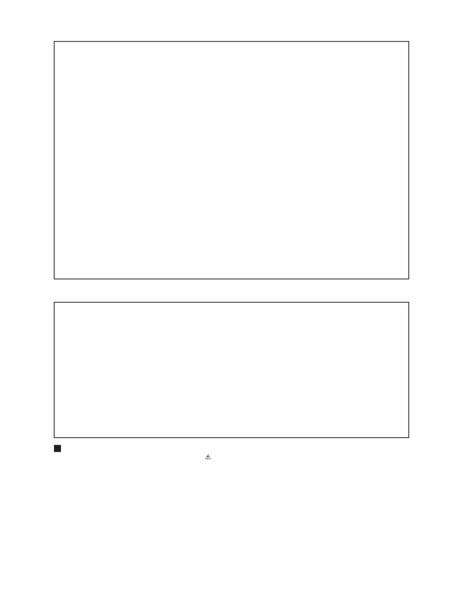
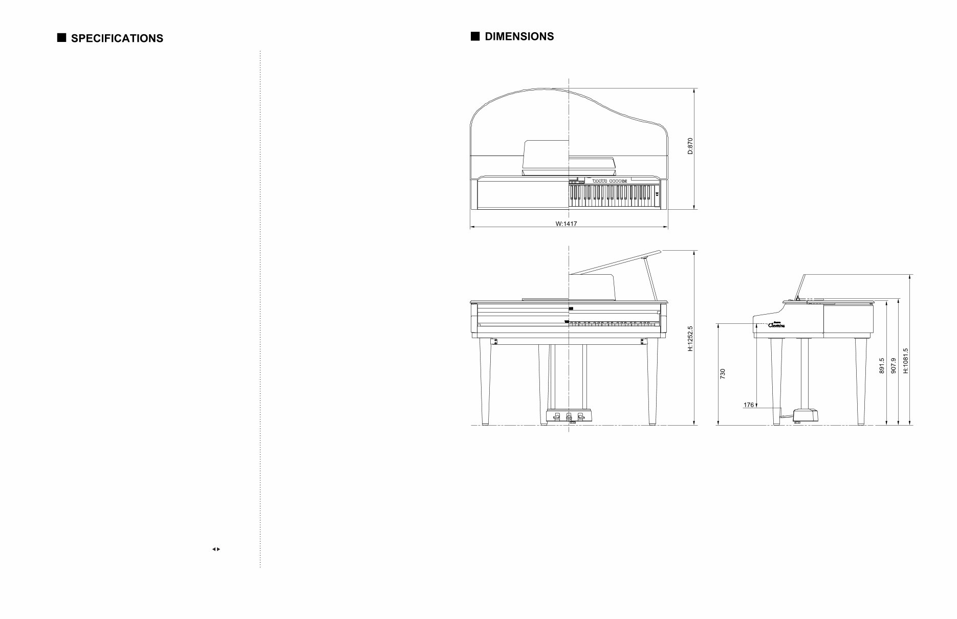
3 CVP-600 KEYBOARD • 88 keys (A-1 - C7) TONEGENERATOR • AWM (Advanced Wave Memory) MAXIMUMSIMULTANEOUS POLYPHONY • 64 VOICES • Clavinova voices: 133 • XG voices: 480 • Drum Kits: 12 sets • Voice Groups: Piano, Electric Piano, Vibraphone, Guitar, Clavinova Tone/Synth, Organ, Strings/Choir, Brass, Sax/ Flute, Bass, Drums, XG Organ Combination, Dual/Split EFFECTS • Effect (25 types), Reverb (16 types) TONE CONTROLS • Master Equalizer ACCOMPANIMENT STYLES • Accompaniment Styles: 100; Pianist Styles: 40 • Style Groups: Pop, 16 Beat, Dance Pop, Rock, Ballad, Jazz, Ballroom, Latin Pop, Traditional, Country, Waltz Disk/Custom Pianist • Controls: Start/Stop, Syncro, Tap, Intro, Main A, Main B, Auto-fill, Ending, Fade in/out buttonsMetronome, Tempo -/+ buttons AUTO ACCOMPANIMENT • Single Finger, Multi Finger, Fingered, Full Keybaord Harmony, Pianist, One Touch Setting, Virtual Arranger, Synchro Stop, Small ACMP, Chord Assist, Individual Part Volume Control (Mixer) REGISTRATION • Bank A - E x 4 memory locations (20), Freeze SONG PLAY MODE • Song Playback, Repeat, Volume control of individual Parts (Mixer) • Controls: Song, Play/Stop, Rewind, Fast forward, Pause • Guide Control: Easy Play, Next Note, Sound Repeat Lyric Disply LCD/CONTROLS • 320 x 240 dot liquid crystal display, Contrast dial, Beat lamp, Function button, Mixer button, Page buttons, Display hold button, LCD buttons, data dial, -/+ buttons, Exit button VOLUM E CONTROLS • Master volume, ACMP/Song volume DEMO/HELP • 27 Demo Songs; 5 help languages (English, Japanese, German, French, Spanish) DISK DRIVE • 3.5-inch micro floppy disk drive PEDAL CONTROLS RIGHT Damper CENTER Sostenuto LEFT Soft, Start/Stop, Harmony On/ Off, Registration+, Main A, Main B, Ending/Rit, Break, Fade In/Out JACKS AND TERMINALS • Headphone jacks x 2, AUX OUT jacks (L/L+R, R), AUX IN jacks (L/L+R, R), EXP.PEDAL jack, MIC. jack, TO HOST terminal, MIDI terminals (IN, OUT, THRU) INPUT/OUTPUT SPECIFICATIONS • AUX OUT: Output Impedance: 600 ohm • AUX IN: Input Impedance: 10 k ohm; Input Sensitivity: -10 dBm MAIN AMPLIFIERS • 120 W (60 W x 2) SPEAKERS • 16 cm x 2, 5 cm x 4 DIMENSIONS (W x D x H) • Lid down 1417 mm x 870 mm x 908 mm (55-3/4" x 34-1/4" x 35-3/4") • Lid up 1417 mm x 870 mm x 1253 mm (55-3/4" x 34-1/4" x 49-3/8") WEIGHT • 84.0 kg (185 lbs., 3 oz.) Output level Refer to the TEST PROGRAM section of this manual. Unit: mm
5 CVP-600 • Main unit • Control Panel 2NC-V281420 2
CVP-600 6 × 28CA1-8811586
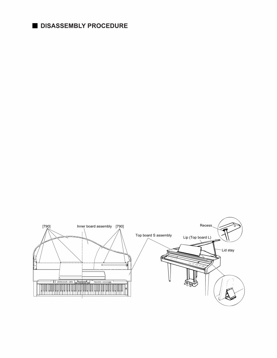
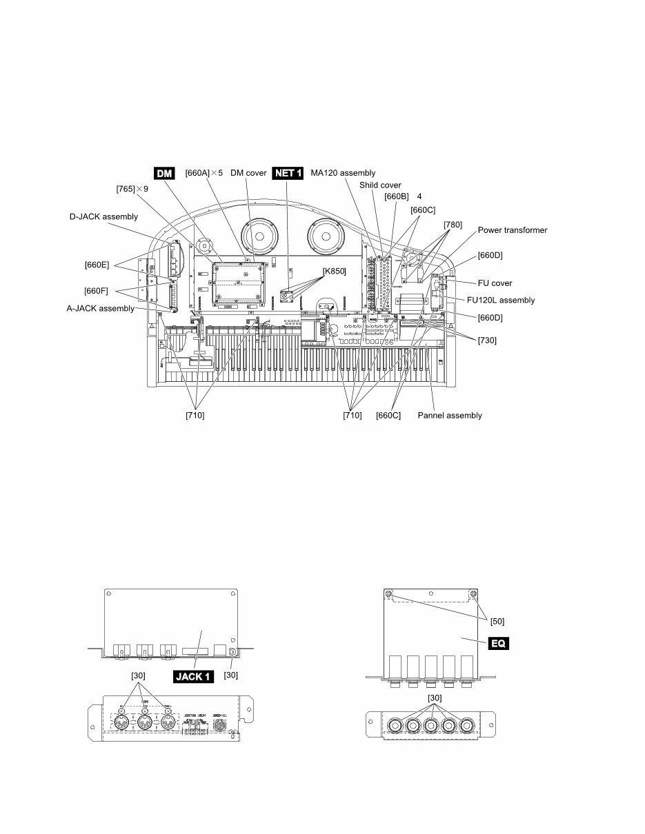
CVP-600 7 1 Inner Board Assembly And Top Board S As- sembly 1-1 Raise up the music rest and set it. (Fig. 1) 1-2 Open the lid carefully and remove the ten (10) screws marked [790]. The inner board assembly can then be removed. (Fig. 1) CAUTION Be careful not to catch your fingers when raising or lowering the lid. Make sure that the top board assembly is fixed firmly with your hand or by another tool while re- moving the screws. Do not attempt to open the lid too wide, since this can cause excessive force to be imposed on the adjustment mechanism, possibly resulting in dam- age to the mechanism or even injury. 1-3 After removing the inner board assembly, raise the lid stay and lower the lid carefully so that the end of the stay fits into the recess of the lid. (Fig. 1) 1-4 Shut the key cover assembly, slide the top board S assembly to the front and lift up. The top board S assembly can then be removed. (Fig. 1) [790]: Tapping Screw-1 3.5X12 MFZN2BL (VV732500) (Fig.1) * After removing the top board S assembly, shut the key cover assembly. This will give you access to the circuit boards and the units located on the keybed. These units can be removed by removing the screws listed below. DM Circuit Board Remove the five (5) screws marked [K660A]. The DM cover can then be removed. (Fig. 2) Remove the nine (9) screws marked [K765]. The DM circuit board can then be removed. (Fig. 2) MA120 assembly Remove the four (4) screws marked [K660B]. The shield cover can then be removed. (Fig. 2) Remove the two (2) screws marked [K660C]. The MA120 assembly can then be removed. (Fig. 2) FU120L assembly Remove the two (2) screws marked [K660D]. The FU cover can then be removed. (Fig. 2) Remove the two (2) screws marked [K660E]. The FU120L assembly can then be removed. (Fig. 2)
CVP-600 8 (Fig. 2) Power transformer Remove the four (4) screws marked [780]. The power transformer can then be removed. (Fig. 2) D-JACK assembly Remove the two (2) screws marked [660F]. The D- jack assembly can then be removed. (Fig. 2) A-JACK assembly Remove the two (2) screws marked [660G]. The A- jack assembly can then be removed. (Fig. 2) NET1 Circuit Board Remove the four (4) screws marked [850]. The NET1 circuit board can then be removed. (Fig. 2) [660]: Bind Head Tapping Screw-1 3.5X12 MFZN2BL (EP030340) [710]: Bind Head Tapping Screw-B 4.0X10 MFZN2BL (EP600240) [730]: Bind Head Screw 4.0X10 MFZN2Y (EX001310) 2 JACK1 Circuit board 2-1 Remove the top board S assembly and the D-JACK assembly. (See procedure 1) 2-2 Remove the four (4) screws marked [30]. The JACK1 circuit board can then be removed. (Fig. 3) 3 EQ Circuit board 2-1 Remove the top board S assembly and the A-JACK assembly. (See procedure 1) 2-2 Remove the two (2) screws marked [50] and the five (5) hexagonal nuts marked [30]. The EQ circuit board can then be removed. (Fig. 4) [30]: Bind Head Tapping Screw-B 3.0X8 MFZN2BL (EP600190) [765]: Bind Head Tapping Screw-B 3.0X8 MFZN2BL (EP600240) [780]: Bind Head Screw 4.0X14 MFZN2Y (EG340210) [850]: Bind Head Tapping Screw-1 3.5X20 MFZN2Y (EP030470) [30]: Hexagonal Nut 12.0 14X2 MFZN2BL (VB508600) [50]: Bind Head Tapping Screw-B 3.0X8 MFZN2BL (EP600190) (Fig. 3) (Fig. 4) ×
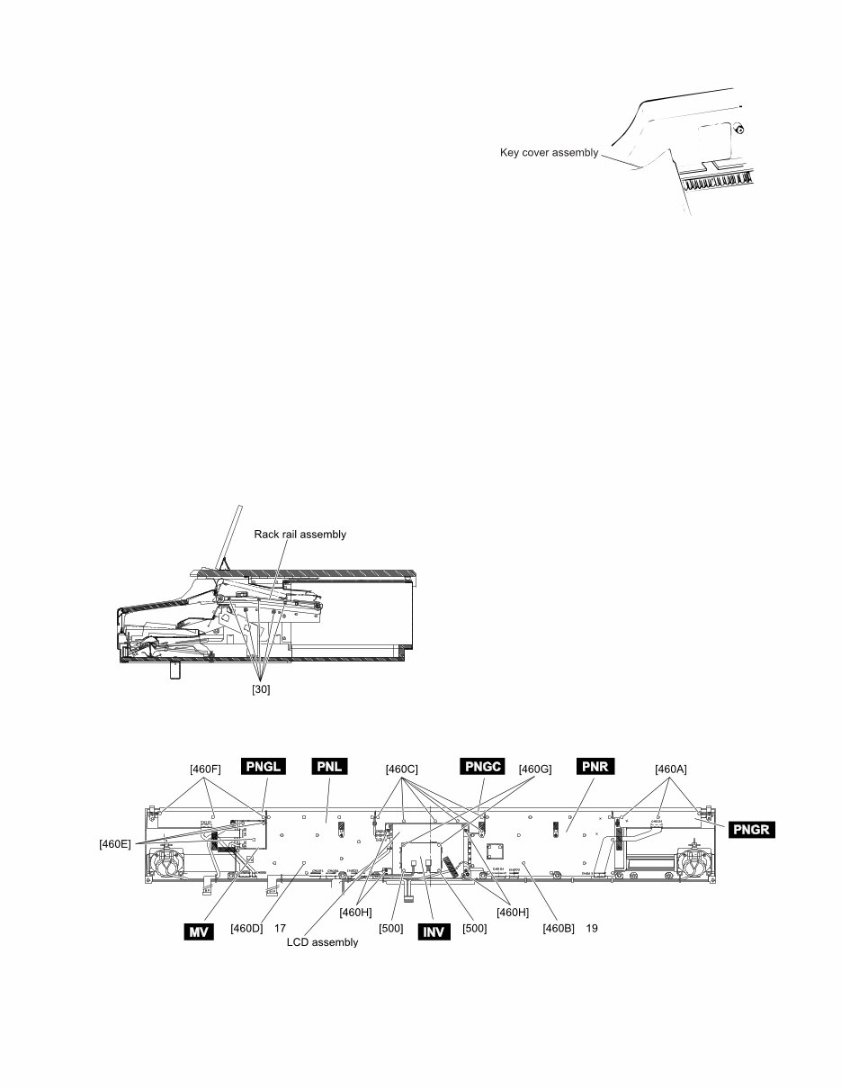
CVP-600 9 4 Key Cover assembly 4-1 Remove the top board S assembly. (See procedure 1) 4-2 Shut the key cover assembly, set the end of the rod at the slits of the guide and lift up. The key cover assembly can then be removed. (Fig. 5) 5 Panel assembly 5-1 Remove the top board S assembly. (See procedure 1) 5-2 Remove the key cover assembly. (See procedure 4) 5-3 Remove the five (5) screws marked [30]. The right and left side of the rack rail assembly can then be removed. (Fig. 6) 5-4 Remove the seven (7) screws marked [K710] and the two (2) screws marked [K730]. (Fig. 2) 5-5 Slide the panel assembly backward and lift up. The panel assembly can then be removed. * This will give you access to the circuit boards on the panel. These circuit boards can be removed by re- moving the following screws. PNGR circuit board Remove the three (3) screws marked [460A]. The PNGR circuit board can then be removed. (Fig. 7) PNR circuit board Remove the nineteen (19) screws marked [460B]. The PNR circuit board can then be removed. (Fig. 7) PNGC circuit board Remove the six (6) screws marked [460C]. The PNGC circuit board can then be removed. (Fig. 7) PNL circuit board Remove the seventeen (17) screws marked [460D]. The PNL circuit board can then be removed. (Fig. 7) MV circuit board Remove the three (3) screws marked [460E]. The MV circuit board can then be removed. (Fig. 7) PNGL circuit board Remove the three (3) screws marked [460F]. The PNGL circuit board can then be removed. (Fig. 7) INV circuit board Remove the two (2) screw marked [500] and the two (2) screws marked [460G]. The INV circuit board can then be removed. (Fig. 7) LCD assembly Remove the four (4) screws marked [460H]. The LCD assembly can then be removed. (Fig. 7) (Fig. 7) [460]: Bind Head Tapping Screw-B 3.0X8 MFZN2Y (EP600250) [500]: Bind Head Tapping Screw-B 3.0X10 MFZN2BL (EP600140) (Fig. 5) (Fig. 6) [30]: Bind Head Tapping Screw-B 3.0X8 MFZN2Y (EP600250) × ×
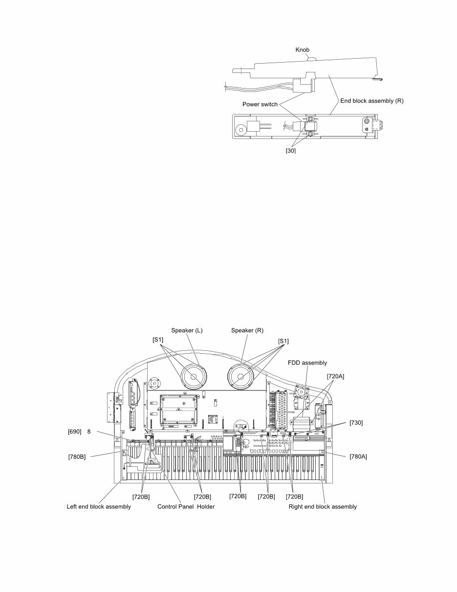
CVP-600 10 6 POWER Switch 6-1 Remove the top board S assembly. (See procedure 1) 6-2 Remove the key cover assembly. (See procedure 4) 6-3 Remove the panel assembly. (See procedure 5) 6-4 Remove the screw marked [780A]. The right end block assembly can then be removed. (Fig. 9) 6-5 Remove the two (2) screws marked [30]. The POWER switch can then be removed from the right end block. (Fig. 8) 6-6 Pull the knob of the switch. (Fig. 8) 7 FDD assembly 7-1 Remove the top board S assembly. (See procedure 1) 7-2 Remove the two (2) screws marked [720A] and the two (2) screws marked [730]. The FDD assembly can then be removed. (Fig. 9) 8 Main Speakers 8-1 Remove the top board S assembly. (See procedure 1) 8-5 Remove the four (4) screws marked [S1]. The main speaker L can then be removed. (Fig. 9) *The right and left speakers can be removed in the same manner. 9 Keyboard Unit 9-1 Remove the top board S assembly. (See procedure 1) 9-2 Remove the key cover assembly. (See procedure 4) 9-3 Remove the panel assembly. (See procedure 5) 9-4 Remove the ten (10) screws marked [720B]. The five (5) control panel holders can then be removed. (Fig. 9) 9-5 Remove both of the screws marked [780A] and [K780B]. The right and the left end block assembies can then be removed. (Fig. 9) 9-6 Remove the eight (8) screws marked [690]. The key- board unit can then be removed from the main unit. (Fig. 9) [30]: Bind Head Tapping Screw-B 3.0X8 MFZN2BL (EP600190) (Fig. 8) (Fig. 9) [690]: Pan Head Screw 5.0X25 MFZN2Y PW (VV040700) [700]: Bind Head Tapping Screw-1 4.0X14 MFZN2Y (EP040230) [720]: PW Head Tapping Screw-1 3.5X18-10 MFZN2Y (VZ057000) [730]: Bind Head Screw 4.0X10 MFZN2Y (EX001310) [780]: Bind Head Screw 4.0X14 MFZN2Y (EG340210) [S1]: Bind Head Tapping Screw-1 4.0X16 MFZN2BL (EP040250) ×
This comprehensive service manual includes specifications, panel layout, circuit board layout, block diagram, disassembly procedure, LSI pin description, IC block diagram, circuit boards, inspection, MIDI implementation chart, overall circuit diagram, and parts list. It provides detailed instructions and images for repairing and servicing Yamaha products. The manual is an official high-resolution document, ensuring excellent print quality. Instant access is available after payment, with no shipping delays. The manual is in English and is compatible with various platforms such as Windows, MAC, and Linux.
Whether you are a professional mechanic or a DIY enthusiast, this manual is an invaluable resource for maintaining and repairing Yamaha products. For other Yamaha product service manuals, feel free to inquire!