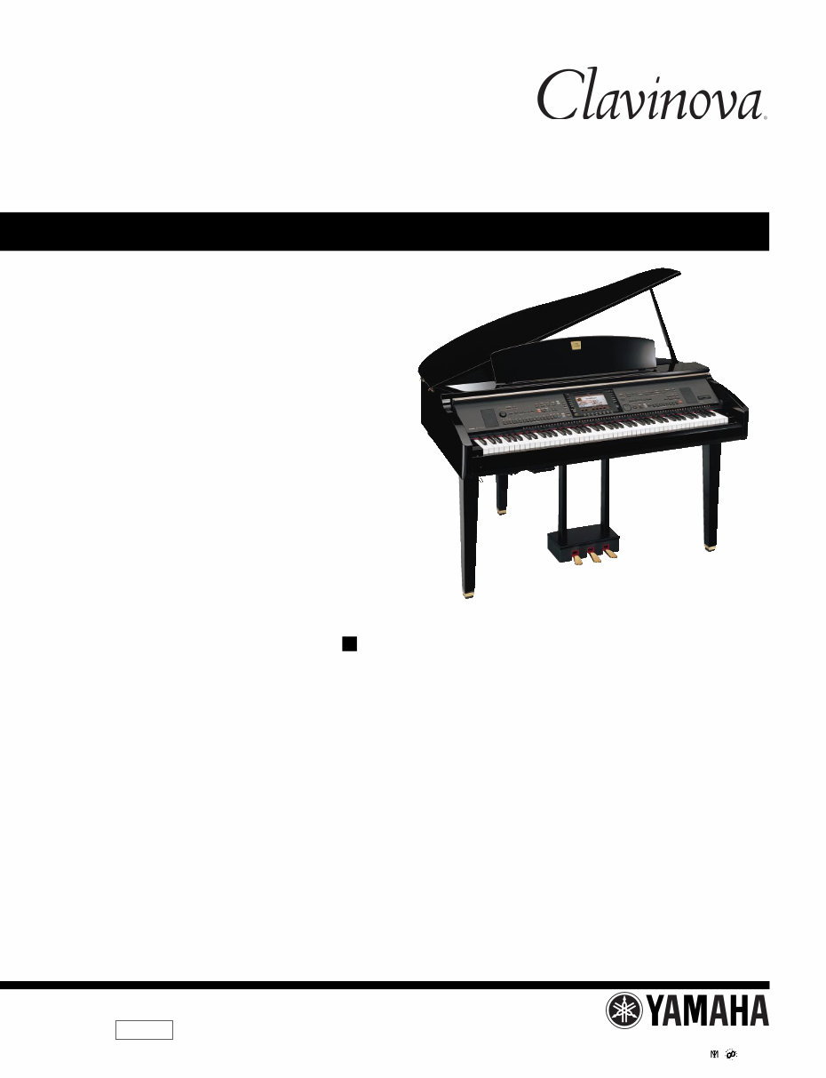
CONTENTS SPECIFICATIONS ................................................................... 3 PANEL LAYOUT ...................................................................... 5 DISASSEMBLY PROCEDURE ................................................ 8 LSI PIN DESCRIPTION .......................................................... 25 IC BLOCK DIAGRAM ............................................................. 34 CIRCUIT BOARDS ................................................................. 36 TEST PROGRAM ................................................................... 71 VERSION UPGRADE ............................................................. 78 DATA BACKUP ....................................................................... 81 RESTORING THE FACTORY-PROGRAMMED SETTING .... 85 INITIALIZING INTERNET SETTING ...................................... 87 FACTORY SET ....................................................................... 87 SYSTEM BOOTING FLOWCHART ........................................ 88 MIDI IMPLEMENTATION CHART .......................................... 90 MIDI DATA FORMAT .............................................................. 91 PARTS LIST BLOCK DIAGRAM CIRCUIT BOARD LAYOUT & WIRING OVERALL CIRCUIT DIAGRAM SERVICE MANUAL CL 001729 HAMAMATSU, JAPAN CVP-309GP Copyright (c) Yamaha Corporation. All rights reserved. PDF-K5192 ’04.08 CVP-309GP
2 CVP-309GP WARNING: CHEMICAL CONTENT NOTICE! The solder used in the production of this product contains LEAD. In addition, other electrical/electronic and/or plastic (Where applicable) components may also contain traces of chemicals found by the California Health and Welfare Agency (and possibly other entities) to cause cancer and/or birth defects or other reproductive harm. DO NOT PLACE SOLDER, ELECTRICAL/ELECTRONIC OR PLASTIC COMPONENTS IN YOUR MOUTH FOR ANY REASON WHAT SO EVER! Avoid prolonged, unprotected contact between solder and your skin! When soldering, do not inhale solder fumes or expose eyes to solder/flux vapor! If you come in contact with solder or components located inside the enclosure of this product, wash your hands before handling food. IMPORTANT NOTICE This manual has been provided for the use of authorized Yamaha Retailers and their service personnel. It has been assumed that basic service procedures inherent to the industry, and more specifically Yamaha Products, are already known and under- stood by the users, and have therefore not been restated. WARNING : Failure to follow appropriate service and safety procedures when servicing this product may result in per- sonal injury, destruction of expensive components and failure of the product to perform as specified. For these reasons, we advise all Yamaha product owners that all service required should be performed by an authorized Yamaha Retailer or the appointed service representative. IMPORTANT : This presentation or sale of this manual to any individual or firm does not constitute authorization certifi- cation, recognition of any applicable technical capabilities, or establish a principal-agent relationship of any form. The data provided is belived to be accurate and applicable to the unit(s) indicated on the cover. The research engineering, and service departments of Yamaha are continually striving to improve Yamaha products. Modifications are, therefore, inevitable and changes in specification are subject to change without notice or obligation to retrofit. Should any discrepancy appear to exist, please contact the distributor’s Service Division. WARNING : Static discharges can destroy expensive components. Discharge any static electricity your body may have accumulated by grounding yourself to the ground bus in the unit (heavy gauge black wires connect to this bus.) IMPORTANT : Turn the unit OFF during disassembly and parts replacement. Recheck all work before you apply power to the unit. Components having special characteristics are marked and must be replaced with parts having specification equal to those originally installed. WARNING IMPORTANT NOTICE FOR THE UNITED KINGDOM Connecting the Plug and Cord IMPORTANT : The wires in this mains lead are coloured in accordance with the following code: BLUE : NEUTRAL BROWN : LIVE As the colours of the wires in the mains lead of this apparatus may not correspond with the coloured makings identifying the terminals in your plug proceed as follows: The wire which is coloured BLUE must be connected to the terminal which is marked with the letter N or coloured BLACK. The wire which is coloured BROWN must be connected to the terminal which is marked with the letter L or coloured RED. Making sure that neither core is connected to the earth terminal of the three pin plug. Saving and backing up your data The data of the types listed below are lost when you turn off the power to the instrument. Save the data to the USER tab display, floppy disk, SmartMedia card, or appropriate external media. • Recorded/Edited Songs • Created/Edited Styles • Edited Voices • Memorized One Touch Settings • Edited MIDI settings SAVING DATA Be sure to perform it
CVP-309GP 3 Sound Source AWM Dynamic Stereo Sampling Keyboard Natural Wood Keyboard 88 keys LCD Display 640 x 480 dots VGA color LCD Music Score, Lyrics YES Wallpaper Customize YES Voice Polyphony (max) 128 + 128 Voice Selection 451 voices + 480 XG Voices 17 Drum/SFX Kits + GM2 + GS (GS Voices for GS Song playback) Mega Voice 10 Regular Voice 338 Natural! Voice 38 Sweet! Voice 14 Cool! Voice 19 Live! Voice 22 Organ Flutes! 10 Sound Creator YES Effects Effect Blocks Reverb/Chorus/DSP 8 Microphone 1 Effect Types Reverb/Chorus/DSP Reverb: 35 Preset + 3 User Chorus: 31 Preset + 3 User DSP 1: 183 Preset + 3 User DSP 2–5: 182 Preset + 10 User DSP 6: 182 Preset + 10 User Master EQ 5 Preset + 2 User Master Compressor 5 Preset + 5 User Part EQ 27 Parts Vocal Harmony 61 Preset + 10 User Accompaniment Style Accompaniment Styles 386 Pro Styles 316 Session Styles 34 Pianist Styles 36 Mega Voice Styles YES Fingering Single Finger, Fingered, Fingered On Bass, Multi Finger, AI Fingered, Full Keyboard, AI Full Keyboard Style Creator YES OTS (One Touch Setting) 4 for Each Style OTS Link YES Music Finder Preset YES Edit YES Song Preset Songs 120 Guide Follow Lights, Any Key, Karao-Key,Vocal CueTIME Guide Lamp YES performance assistant technology YES Recording Quick Recording, Multi Recording, Step Recording, Song Editing Record Channels 16 Internet Direct Connection External Adapter (via USB to DEVICE) Memory Device Floppy Disk (2HD, 2DD) External Adapter (via USB to DEVICE) Hard Disk External Adapter (via USB to DEVICE) Flash Memory (Internal) 3.3 MB SmartMedia Slot 1 (Compatible with SmartMedia FAT 12 or 16 format.) SPECIFICATIONS
4 CVP-309GP Tempo Tempo Range 5–500, Tap Tempo Metronome YES Sound Bell on/off, Human Voices (5 Languages) Registration Memory Buttons 8 Regist. Sequence/Freeze YES Others Demo/Help YES Language for Display 6 Languages (English, Japanese, German, French, Spanish, Italian) Direct Access YES Piano Button (incl. Piano Lock) YES Transpose Keyboard/Song/Master Scale Type 9 USB Connection USB to HOST (Computer) YES USB to DEVICE YES (2 terminals) Other Connectors PHONES x 2, MIDI (THRU, OUT, IN), AUX PEDAL, AUX IN (L/L+R, R), AUX OUT (L/L+R, R), AUX OUT (LEVEL FIXED) (L, R), MIC (INPUT VOLUME, MIC./LINE IN), OPTICAL OUT, VIDEO OUT Pedals Functions VOLUME, SUSTAIN, SOSTENUTO, SOFT, GLIDE, SONG PLAY/PAUSE, STYLE START/STOP, etc. Amplifiers/Speakers Amplifiers iAFC 60 W x 2 + 20 W x 2 YES Speakers (16 cm + 5 cm + 3cm(dome)) x 2 +10cm x 2 Dimensions [W x D x H] (Lid up) 1435 mm x 1147 mm x 907 mm [56-1/2" x 45-1/8" x 35-11/16"] (1435 mm x 1147 mm x 1381 mm [56-1/2" x 45-1/8" x 54-3/8"] ) Weight Accessories 118 kg (260 lbs., 3oz) Optional Accessories Headphones HPE-160 Foot Switch FC 4/FC 5 Foot Controller FC 7 USB-FDD Unit UD-FD01 Guide to Yamaha Online Member Product User Registration The following items may be included or optional, depending on your locale: Floppy Disk Drive, SmartMedia card, Bench "50 greats for the Piano" Music Book, Owner's Manual, Data List Output Impedance PHONES: 33Ω (Recommend) OUTPUT (L/L+R,R): 600Ω AUX OUT (L,R) (LEVEL FIXED): 600Ω
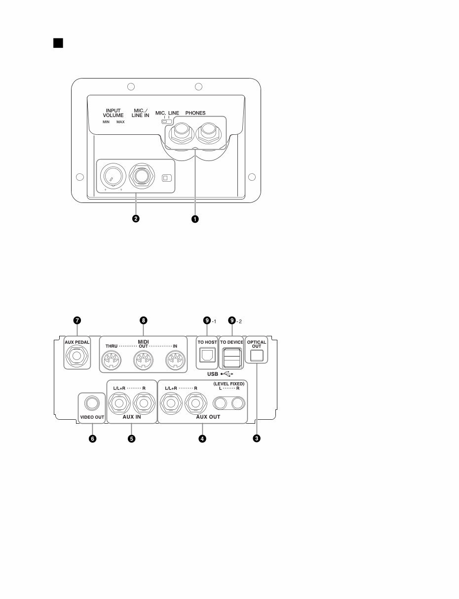
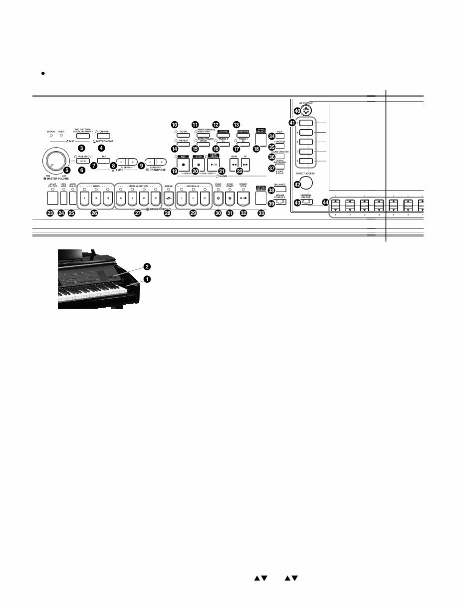
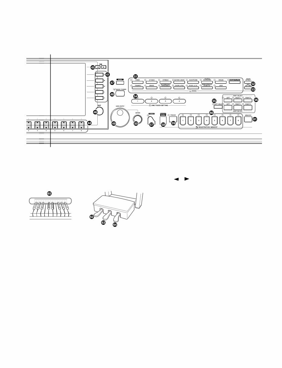
CVP-309GP 5 q [PHONES] jacks w • [MIC./LINE IN] jack • [INPUT VOLUME] dial e [OPTICAL OUT] jack r [AUX OUT] jacks t [AUX IN] jacks y [VIDEO OUT] jack u [AUX PEDAL] jack i [MIDI] terminals o-1 [USB TO HOST] terminal o-2 [USB TO DEVICE] terminal PANEL LAYOUT
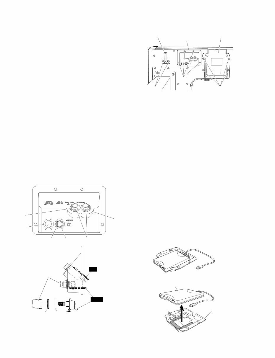
CVP-309GP 8 (Fig. 2) [40]: Hexagonal Nut 12.0x14x2 MFZN2BL (VB508600) [50]: Washer (VJ869400) [N1]: Hexagonal Nut [W1]: Washer [12b]: Truss Head Screw 4.0x10 MFZN2BL (VT196400) [67]: Bind Head Tapping Screw-1 3.5x16 MFZN2BL (EP030260) [78]: Truss Head Screw 4.0x20 MFZN2BL (VB934000) ● Mic. & Phones Unit (Fig. 1) (Fig. 3) <Front view> <Side view> ● FDD Unit [50B] [50B] [50A] Knob [40B] [40A] Knob HP MIC [N1] [W1] [12b] [67] [78] Headphone hanger Mic. & phones unit FDD unit 1. Headphone Hanger (Time required : About 1 minute) Remove the two (2) screws marked [12b]. The headphone hanger can then be removed. (Fig. 1) 2. Mic. & Phones Unit, MIC and HP Circuit Boards (Time required : About 3 minutes each) 2-1. Remove the four (4) screws marked [67]. The mic. & phones unit can then be removed. (Fig. 1) 2-2. MIC Circuit Board 2-2-1. Remove the input volume knob, the hexagonal nut marked [N1] and the washer marked [W1]. (Fig. 2) 2-2-2. Remove the hexagonal nut marked [40A] and the washer marked [50A]. The MIC circuit board can then be removed. (Fig. 2) * When installing the INPUT VOLUME knob, set it to the VOL. MIN position, that is, align the bar on the knob with the point on the case as shown in the figure. (Fig. 2) 2-3. HP Circuit Board Remove the two (2) hexagonal nuts marked [40B] and the two (2) washers marked [50B]. The HP circuit board can then be removed. (Fig. 2) ■ DISASSEMBLY PROCEDURE Double-sided Tape (FDD cushion) FDD holder assembly USB-3.5FDD 3. Floppy Disk Drive (Time required : About 3 minutes) 3-1. Disconnect the USB connector. 3-2. Remove the four (4) screws marked [78]. The FDD unit can then be removed. (Fig. 1) 3-3. Remove the USB-3.5FDD attached by the double-sided tapes from the FDD holder assembly. (Fig. 3) * Note that once you remove the double-sided tape (FDD cushion), you cannot use it again. In the replacing of USB- 3.5 FDD, use new double-sided tapes (FDD cushions) to install the FDD.
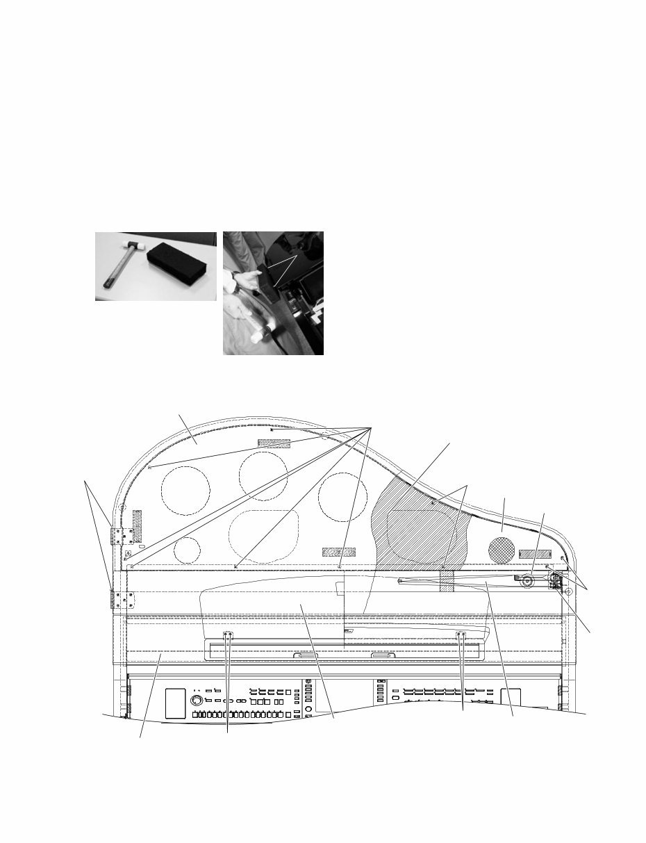
CVP-309GP 9 5. Top Board (L) Assembly (Lid) (Time required : About 3 minutes) Remove the two (2) hinge shafts. The top board (L) assembly (lid) can then be removed. (Fig. 4) 7. Speaker Grille Assembly, Inner Board Assembly (Time required : About 5 minutes) 7-1. Remove the top board (L) assembly (lid). (See procedure 5) 7-2. Remove the speaker grille assembly. (Fig. 4) * The speaker grille assembly is fixed by means of the dual lock fastener. 7-3. Remove the ten (10) screws marked [69]. The inner board assembly can then be removed. (Fig. 4) 6. Top Board (Lid) Stay L & S (Time required : About 4 minutes) 6-1. Remove the top board (L) assembly (lid). (See procedure 5) 6-2. Remove the screw marked [65]. The top board (lid) stay L and S can then be removed. (Fig. 4) [69] [65] [69] [69] Speaker grille assembly Inner board assembly Top board (lid) stay S Top board (lid) stay L Music rest assembly Top board (S) assembly [74] [74] Top board (L) assembly (lid) Hinge shafts Fig. 4 [65]: Bind Head Screw 5.0x50 MFZN2Y (WB272400) [69]: Truss Head Screw 4.0x16 MFZN2BL (V6207400) [74]: Bind Head Tapping Screw-1 3.0x16 MFZN2BL (EP030310) 4. Music Rest Assembly (Time required : About 1 minute) Remove the four (4) screws marked [74]. The music rest assembly can then be removed. (Fig. 4) • Removal of the hinge shaft Hinge Shafts Remove the two (2) hinge shafts one by one.
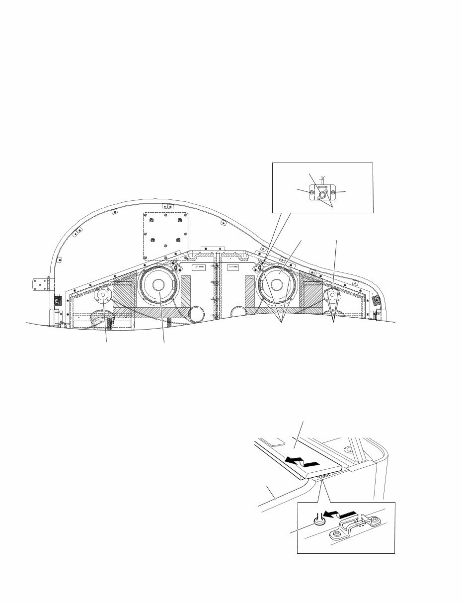
CVP-309GP 10 8. Woofer, Tweeter, AFC Capacitor Mic (Time required : About 7 minutes each) 8-1. Remove the top board (L) assembly (lid). (See procedure 5) 8-2. Remove the speaker grille assembly and the inner board assembly. (See procedure 7) 8-3. Remove the four (4) screws marked [7A]. The woofer can then be removed. (Fig. 5) * The left and right woofer each can then be removed in the same manner. 8-4. Remove the four (4) screws marked [7B]. The tweeter can then be removed. (Fig. 5) * The left and right tweeter each can then be removed in the same manner. [68A] AFC capacitor mic [H29f] [68A] AFC MIC unit Woofer Tweeter [7A] [7B] Woofer Tweeter Fig. 5 [7]: Bind Head Tapping Screw-1 4.0x16 MFZN2BL (EP040250) [68A]: Bind Head Tapping Screw-1 3.5x12 MFZN2Y (EP030240) [H29f]: Plastic Rivet P3065B (V9240700) First lot Plastic Rivet P3055 NIX (WA388200) Second lot ~ 9. Top Board (S) Assembly (Time required : About 5 minutes) 9-1. Close the key cover. 9-2. Remove the top board (L) assembly (lid). (See procedure 5) 9-3. Remove the speaker grille assembly and the inner board assembly. (See procedure 7) 9-4. Raise top board (lid) stay L. 9-5. Move the top board (S) assembly forward, lift it. (Fig. 6) * When reinstalling the top board (S) assembly, be sure not to make scratches on the arm assembly L/R. Fig. 6 8-5. Remove the two (2) screws marked [68A]. The AFC MIC unit can then be removed. (Fig. 5) 8-6. Remove the two (2) plastic rivets marked [H29f]. The AFC capacitor mic can then be removed. (Fig. 5) * The left and right AFC capacitor mic each can then be removed in the same manner. * For removal of the AFC capacitor mic in panel assembly, refer to procedure 15. Top board (S) assembly Strap screw Arm assembly L
The Yamaha CVP-309GP Clavinova Service Manual is a comprehensive guide that provides essential technical information for the repair and maintenance of the Yamaha CVP-309GP Clavinova model. This manual includes detailed specifications, panel layout, disassembly procedures, LSI pin descriptions, IC block diagrams, circuit boards, test programs, version upgrades, data backup methods, restoring factory-programmed settings, initializing internet settings, factory set procedures, system booting flowchart, MIDI implementation chart, MIDI data format, parts list, block diagrams, circuit board layouts, wiring information, and overall circuit diagrams.
This manual is an invaluable resource for both professional mechanics and DIY enthusiasts who require in-depth knowledge of the Yamaha CVP-309GP Clavinova model. It is available in English language format and can be accessed on both Windows and Mac platforms.


 Lifetime Access




