SERVICE MANUAL Copyright (c) Yamaha Corporation. All rights reserved. PDF M I ’06.05 SY 011825 ■ CONTENTS (目次) SPECIFICATIONS (総合仕様) ................................................... 3 PANEL LAYOUT (パネルレイアウト) ...................................... 4 DISASSEMBLY PROCEDURE (分解手順) ............................... 7 LSI PIN DESCRIPTION (LSI端子機能表) ............................... 13 IC BLOCK DIAGRAM (ICブロック図) .................................... 16 CIRCUIT BOARDS (シート基板図) ........................................ 16 TEST PROGRAM (テストプログラム) .............................. 26/33 BULK DUMP(BACKING UP THE DATA) (バルクダンプ(データのバックアップ)) ........................ 40/43 FACTORY PRESET RECALL (初期設定に戻すには) ......... 46/48 MESSAGE LIST (メッセージ一覧) ......................................... 50 SYSTEM BOOTING FLOWCHART (起動フローチャート) ..................................................... 51/52 MIDI IMPLEMENTATION CHART (VOICE) ........................... 53 MIDI IMPLEMENTATION CHART (MASTER) ....................... 54 MIDI DATA FORMAT ............................................................. 55 PARTS LIST BLOCK DIAGRAM (ブロックダイアグラム) CIRCUIT BOARD LAYOUT & WIRING (ユニットレイアウト&結線図) OVERALL CIRCUIT DIAGRAM (総回路図) 20060525-147000
CP33 2 IMPORTANT NOTICE This manual has been provided for the use of authorized Yamaha Retailers and their service personnel. It has been assumed that basic service procedures inherent to the industry, and more specifically Yamaha Products, are already known and understood by the users, and have therefore not been restated. WARNING : Failure to follow appropriate service and safety procedures when servicing this product may result in personal injury, destruction of expensive components and failure of the product to perform as specified. For these reasons, we advise all Yamaha product owners that all service required should be performed by an authorized Yamaha Retailer or the appointed service representative. IMPORTANT : This presentation or sale of this manual to any individual or firm does not constitute authorization, certification, recognition of any applicable technical capabilities, or establish a principal-agent relationship of any form. The data provided is believed to be accurate and applicable to the unit (s) indicated on the cover. The research engineering, and service departments of Yamaha are continually striving to improve Yamaha products. Modifications are, therefore, inevitable and changes in specification are subject to change without notice or obligation to retrofit. Should any discrepancy appear to exist, please contact the distributor’s Service Division. WARNING : Static discharges can destroy expensive components. Discharge any static electricity your body may have accumulated by grounding yourself to the ground bus in the unit (heavy gauge black wires connect to this bus). IMPORTANT : Turn the unit OFF during disassembly and parts replacement. Recheck all work before you apply power to the unit. WARNING : CHEMICAL CONTENT NOTICE ! The solder used in the production of this product contains LEAD. In addition, other electrical/electronic and/or plastic (where applicable) components may also contain traces of chemicals found by the California Health and Welfare Agency (and possibly other entities) to cause cancer and/or birth defects or other reproductive harm. DO NOT PLACE SOLDER, ELECTRICAL/ELECTRONIC OR PLASTIC COMPONENTS IN YOUR MOUTH FOR ANY REASON WHAT SO EVER! Avoid prolonged, unprotected contact between solder and your skin! When soldering, do not inhale solder fumes or expose eyes to solder/flux vapor! If you come in contact with solder or components located inside the enclosure of this product, wash your hands before handling food. ■ WARNING Components having special characteristics are marked Z and must be replaced with parts having specification equal to those originally installed. Z印の部品は、安全を維持するために重要な部品です。交換する場合は、安全のために必ず指定の部品をご使用ください。
CP33 3 ■ SPECIFICATIONS Item Keyboard Sound Source Polyphony (max.) Voice Selection Effect Controls Pedal Controller Jacks/Connectors Dimensions (W x D x H) Weight Accessories CP33 GH keyboard 88 keys (A-1 – C7) AWM Dynamic Stereo Sampling 64 14 x 2 variations for each Voice Reverb, Effect, Brilliance Dual, Split, Click, Transpose, Touch (Hard/Medium/Soft/Fixed), Functions SUSTAIN PEDAL (can be used with half-pedal effect), AUX PEDAL (assignable to various functions) Master Volume Dial, Pitch Bend Wheel, Modulation Wheel, Zone Control Sliders MIDI (IN/OUT), PHONES, OUTPUT (L/MONO, R), FOOT PEDAL (SUSTAIN/AUX), USB TO HOST, DC IN 1312 x 330 x 151 mm (51-2/3" x 13 x 5-15/16") 18 kg (39 lbs., 11 oz) Owner’s Manual, Foot Pedal FC3, Yamaha PA-3C power adaptor ■ 総合仕様 項目 鍵盤 音源 最大同時発音数 ボイス数 効果 コントロール ペダル コントローラー 付属端子 定格電源 消費電力 寸法(間口×奥行き×高さ) (ペダルユニットを除く) 質量(ペダルユニットを除く) 付属品 内容 GH 鍵盤 88 鍵 AWM ダイナミックステレオサンプリング 64 14 × 2 バリエーション ブリリアンス、リバーブ、エフェクト デュアル、スプリット、クリック、トランスポーズ、タッチ(ハード / ミディアム / ソフト / フィッ クスト)、各種ファンクション サステイン(ハーフペダル対応)、多機能割り当て マスターボリュームダイアル、ピッチベンドホイール、モジュレーションホイール、 ゾーンコントロールスライダー MIDI IN/OUT 、PHONES(ステレオ標準フォーンジャック)、OUTPUT L/MONO R(標準 フォーンジャック)、FOOT PEDAL(SUSTAIN/AUX)、USB TO HOST 、DC IN 12V 電源アダプター PA-3C 8.0 W 1312mm x 330mm x 151mm 18 kg 取扱説明書、フットペダル FC3 、電源アダプター PA-3C 、保証書
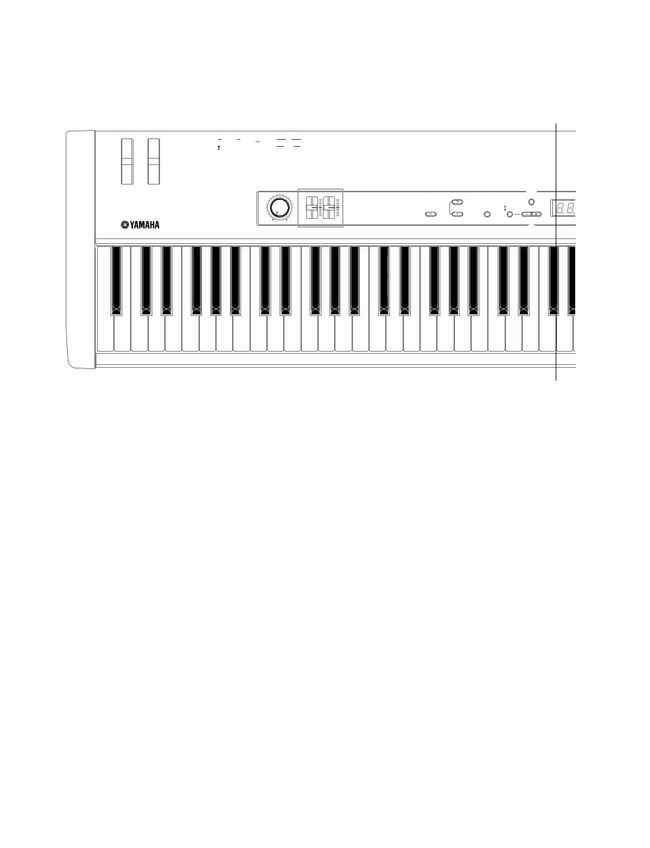
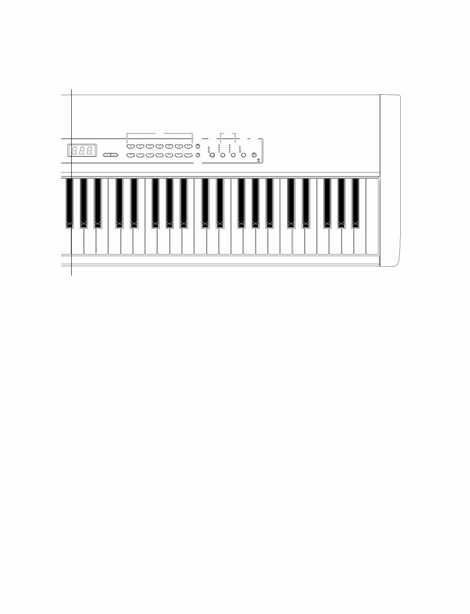
CP33 4 1 Pitch bend wheel 2 Modulation wheel 3 [MASTER VOLUME] dial 4 [ZONE CONTROL] sliders 5 [TRANSPOSE] button 6 [MASTER] button 7 [MASTER EDIT] button 8 [DEMO] button 9 TEMPO/FUNCTION [–][+] button ) [CLICK] button ■ PANEL LAYOUT(パネルレイアウト) Front Panel (フロントパネル) TEMPO/FUNCTION DEMO MASTER TRANSPOSE ZONE CONTROL MASTER VOLUME MAX MIN ZONE 1 ZONE 2 MASTER EDIT MASTER TEMPO/OTHER CLICK ON/OFF TEMPO FUNCTION DC-IN FOOT PEDAL USB AUX STANDBY PHONES MIDI OUT IN L/MONO R OUTPUT ON SUSTAIN 1 2 3 4 5 8 6 ) 9 7 A-1 B-1 C0 D0 E0 F0 G0 A0 B0 C1 D1 E1 F1 G1 A1 B1 C2 D2 E2 F2 G2 A2 B2 C3 D3 E3 F3 G3 A' A 1 ピッチベンドホイール 2 モジュレーションホイール 3 [MASTER VOLUME] (マスターボリューム) ダイアル 4 [ZONE CONTROL] (ゾーンコントロール)スライダー 5 [TRANSPOSE] (トランスポーズ)ボタン 6 [MASTER] (マスター)ボタン 7 [MASTER EDIT] (マスターエディット)ボタン 8 [DEMO] (デモ)ボタン 9 [TEMPO/FUNCTION(テンポ/ファンクション) [-] [+] ボタン ) [CLICK] (クリック)ボタン
CP33 5 GRAND PIANO 1 1 CHURCH ORGAN 8 GRAND PIANO 2 2 JAZZ ORGAN 9 MONO PIANO 3 HARPSI- CHORD 10 E. PIANO 1 4 STRINGS/ CHOIR 11 E. PIANO 2 5 GUITAR 12 E. CLAVI- CHORD 6 WOOD BASS 13 VIBRA- PHONE 7 E. BASS 14 VARIATION MEMORY SPLIT VOICE/MASTER TEMPO/OTHER VALUE BRILLIANCE REVERB EFFECT TOUCH STAGE PIANO CP33 BRIGHT NORMAL MELLOW HALL 1 HALL 2 STAGE PHASER TREMOLO CHORUS ROTARY SP HARD MEDIUM ROOM SOFT NO YES ! @ # $ ^ % & * F3 G3 A3 B3 C4 D4 E4 F4 G4 A4 B4 C5 D5 E5 F5 G5 A5 B5 C6 D6 E6 F6 G6 A6 B6 C7 PANEL LOCK A' A ! [NO/–], [YES/+] button @ Voice group buttons # [VARIATION/MEMORY] button $ [SPLIT] button % [BRILLIANCE] button ^ [REVERB] button, [EFFECT] button & [TOUCH] button * [PANEL LOCK] button ! [NO/-] (ノー) [YES/+] (イエス) ボタン @ ボイスボタン # [VARIATION/MEMORY] (バリエーション/メモリー)ボタン $ [SPLIT] (スプリット)ボタン % [BRILLIANCE] (ブリリアンス)ボタン ^ [REVERB] (リバーブ)ボタン、 [EFFECT] (エフェクト)ボタン & [TOUCH] (タッチ)ボタン * [PANEL LOCK] (パネルロック)ボタン
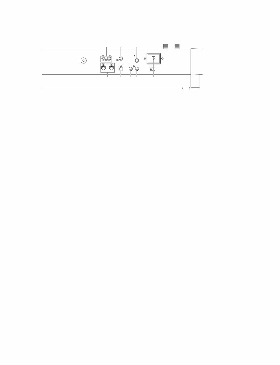
CP33 6 1 OUTPUT [L/MONO][R] jacks 2 MIDI [IN][OUT] connectors 3 [PHONES] jack 4 [USB] connector 5 [STANDBY/ON] switch 6 [SUSTAIN PEDAL] jack 7 [AUX PEDAL] jack 8 [DC IN] jack Rear Panel (リアパネル) DC-IN FOOT PEDAL USB SUSTAIN STANDBY PHONES MIDI OUTPUT OUT IN L/MONO R ON AUX 4 6 7 3 5 1 2 8 1 OUTPUT(アウトプット) [L/MONO][R] 端子 2 MIDI (ミディ) [IN(イン) ] [OUT(アウト) ]端子 3 [PHONES] (フォーンズ)端子 4 [USB] (ユーエスビー)端子 5 [STANDBY/ON] (スタンバイ/オン)スイッチ 6 [SUSTAIN PEDAL] (サステインペダル)端子 7 [AUX PEDAL] (エーユーエックスペダル)端子 8 [DC IN 12V] (ディーシーイン12ボルト)端子
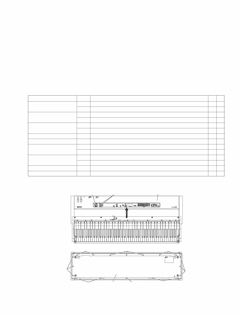
CP33 7 ■ DISASSEMBLY PROCEDURE(分解手順) 1. Upper Case Assembly (Time required: About 2 minutes) Remove the five (5) screws marked [50] and the six (6) screws marked [60] located under the keybed. Move the upper case assembly rearward, and it can then be remove by lifting up. (Fig. 1) 1. 上ケースAss’y (所要時間:約2分) 棚板下より[50] のネジ5本と[60] のネジ6本を外し て、上ケースAss’ yを後方にスライドした後、持ち上 げて外します。 (図1) Circuit board and Assembly Ref. No. Screw QTY Fig. DM 270A Bind Head Tapping Screw-B (Bタイト+BIND) 3.0X6 MFZN2W3 (WE936300) 3 2 420 PW Head Tapping Screw-B (Bタイト+PWH) 3.0X8 MFZN2W3 (WF002600) 1 2 DJACK * 1 320 Bind Head Tapping Screw-B (Bタイト+BIND) 3.0X8 MFZN2B3 (WE774400) 2 2 330A Bind Head Tapping Screw-S (Sタイト+BIND) 3.0X5 MFZN2B3 (WF304200) 2 2 AJACK 410A Bind Head Tapping Screw-B (Bタイト+BIND) 3.0X8 MFZN2W3 (WE774300) 5 2 330B Bind Head Tapping Screw-S (Sタイト+BIND) 3.0X5 MFZN2B3 (WF304200) 2 2 PNL * 1 410B Bind Head Tapping Screw-B (Bタイト+BIND) 3.0X8 MFZN2W3 (WE774300) 10 2 PNR * 1 410C Bind Head Tapping Screw-B (Bタイト+BIND) 3.0X8 MFZN2W3 (WE774300) 8 2 SVR * 1 410D Bind Head Tapping Screw-B (Bタイト+BIND) 3.0X8 MFZN2W3 (WE774300) 4 2 – Slide Knob (スライドツマミ) 2 1 MVR * 1 410E Bind Head Tapping Screw-B (Bタイト+BIND) 3.0X8 MFZN2W3 (WE774300) 2 2 – Volume Knob (Vツマミ) 1 1 Wheel Assembly (PITCH BEND) 270B Bind Head Tapping Screw-B (Bタイト+BIND) 3.0X6 MFZN2W3 (WE936300) 2 2 Wheel Assembly (MODULATION) 270C Bind Head Tapping Screw-B (Bタイト+BIND) 3.0X6 MFZN2W3 (WE936300) 2 2 2. Circuit Boards & Assemblies (Time required: About 4–5 minutes each) 2-1 Remove the upper case assembly. (See procedure 1) 2-2 Each circuit board and assembly can be removed by removing its fixing screws as listed below. 2. 基板とアッセンブリ (所要時間:各約4~5分) 2-1 上ケースAss’ yを外します。 (1項参照) 2-2 次のネジを外すことにより、基板・アッセンブリを外 すことができます。 * 1 When mounting the DJACK, PNL, PNR, SVR and MVR circuit boards, always start by tightening screws q, w in sequence. * 1 DJACK, PNL, PNR, SVR, MVRシートを取り付ける際、まず最初にq、 wのネジを順に締めます。 Fig. 1(図1) [50]: Bind Head Screw (小ネジ+BIND) 4.0X14 MFZN2W3 (WE968700) [60]: Bind Head Screw (小ネジ+BIND) 4.0X20 MFZN2B3 SP (WF002300) [120]: Bind Head Tapping Screw-1 (TP#1+BIND) 3.5X12 MFZN2W3 (WE970900) <Bottom view> (底面) [50] Front Rear [50] [50] Keybed (棚板)� [60] [60] [120] [120] [120] Upper case assembly (上ケースAss'y)� Volume knob (Vツマミ)� Slide knob (スライドツマミ)� 1 2 <Top view> (上面)
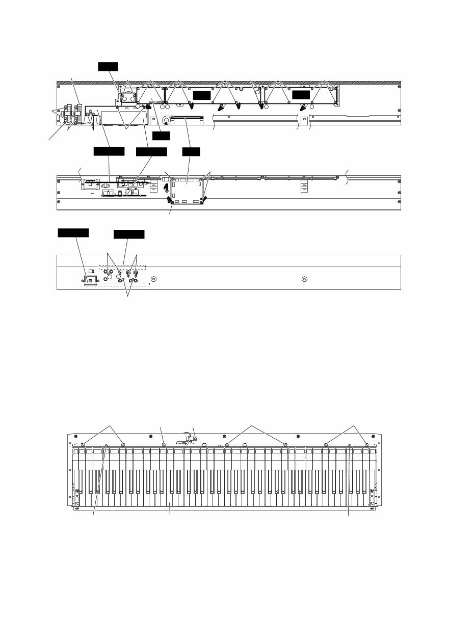
CP33 8 Fig. 3(図3) ● Upper Case Assembly (上ケースAss’y) Fig. 2(図2) 3. Keyboard Assembly (Time required: About 5 minutes) 3-1 Remove the upper case assembly. (See procedure 1) 3-2 Remove the seven (7) screws marked [40] and the three (3) screws marked [80]. The keyboard assembly can then be removed. (Fig. 3) 3. GHD EBUS鍵盤 (所要時間:約5分) 3-1 上ケースAss’ yを外します。 (1項参照) 3-2 [40]のネジ7本と[80]のネジ3本を外し、GHD EBUS 鍵盤を外します。 (図3) [40]: Pan Head Screw (小ネジ+PAN) 5.0X25 MFZN2W3 SW (WF001500) [80]: Bind Head Tapping Screw-1 (TP#1+BIND) 4.0X14 MFZN2W3 (WE971900) PNL PNR Wheel assembly (PITCH BEND) [270B] Wheel assembly (MODULATION) [270C] [410E] [410D] [410B] [410B] [410B] [410C] [410C] [270A] [420] [410A] [410A] [330B] [320] [330A] DJACK AJACK SVR AJACK DJACK DM MVR 1 2 1 2 1 2 1 2 2 1 [270A] [40] Keyboard assembly (GHD EBUS鍵盤)� [40] [40] [80] [80] [40] [80]
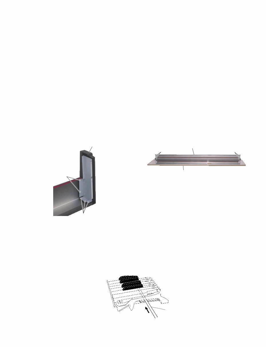
CP33 9 Fig. 4(図4) 4. Side Cover Assembly (L, R) (Time required: About 4 minutes) 4-1 Remove the upper case assembly. (See procedure 1) 4-2 Remove the five (5) screws marked [270D]. The side cover assembly R can then be removed. (Fig. 4) * The side cover assembly L can then be removed in the same manner. 4. 腕木Ass’y (L・R) (所要時間:約4分) 4-1 上ケースAss’ yを外します。 (1項参照) 4-2 [270D]のネジ5本を外し、腕木Ass’ y (R)を外します。 (図4) ※ 腕木Ass’y (L)も同様に外すことができます。 5. Front Rail Assembly (Time required: About 6 minutes) 5-1 Remove the upper case assembly. (See procedure 1) 5-2 Remove the keyboard assembly. (See procedure 3) 5-3 Remove the seven (7) screws marked [120] located under the keybed. (Fig. 1) 5-4 Remove the four (4) screws marked [140]. Move the front rail assembly forward, and it can then be removed. (Fig. 5) * When mounting the front rail assembly, always start by tightening screws q, w in sequence. (Fig. 1) 5. 口金Ass’y (所要時間:約6分) 5-1 上ケースAss’ yを外します。 (1項参照) 5-2 GHD EBUS鍵盤を外します。 (3項参照) 5-3 棚板下側より[120]のネジ7本を外します。 (図1) 5-4 [140]のネジ4本を外し、口金Ass’ yを前方にスライド させて外します。 (図5) ※ 口金Ass’ yを取り付ける際、まず最初にq、 wのネジを順に 締めます。 (図1) Fig. 5(図5) [140]: Bind Head Tapping Screw-B (Bタイト+BIND) 3.0X6 MFZN2W3 (WE936300) [270D]: Bind Head Tapping Screw-B (Bタイト+BIND) 3.0X6 MFZN2W3 (WE936300) Side cover R (腕木R)� [270D] [270D] [140] [140] Front rail assembly (口金Ass'y)� Keybed (棚板)� 6. Disassembling the Keyboard Assembly * After inserting a round stick (Rod: TX000670) between the frame and the keys, remove the circuit boards. (Fig. 6) Round stick (丸棒) (Rod: TX000670) Fig. 6 (図6) 6. GHD EBUS鍵盤の分解 ※ シートをはずす前に、接点ゴムを歪ませないように、フ レームとハンマーの間に丸棒(ロッド:TX000670)を挿入 しておきます。 (図6)
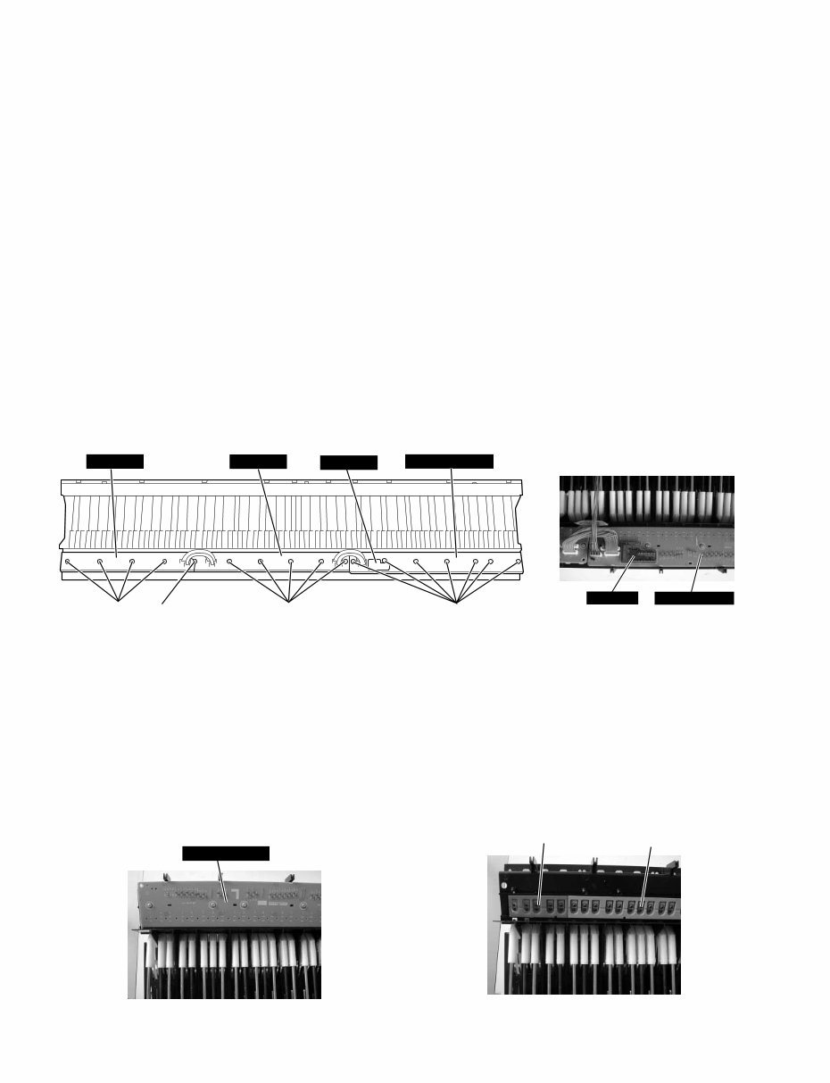
CP33 10 GHD EBUS L GHD M GHD H [260C] [260B] [260A] [262] MK SUB [260]: Bind Head Tapping Screw-P (Pタイト+BIND) 3.0x10 MFZN2W3 (WF001000) [262]: PW Head Tapping Screw-P (Pタイト+PWH) 3.0x10⁻¹⁰ ZMC2W3 (WF765500) 6-1 GHD EBUS L, MK SUB Circuit Board (Time required: About 7 minutes) Remove the seven (7) screws marked [260A]. The GHD EBUS L and MK SUB circuit boards can then be removed. (Fig. 7, 7-1) 6-2 GHD M Circuit Board (Time required: About 7 minutes) Remove the five (5) screws marked [260B] and the screw marked [262]. The GHD M circuit board can then be removed. (Fig. 7) 6-3 GHD H Circuit Board (Time required: About 7 minutes) Remove the four (4) screws marked [260C] and the screw marked [262]. The GHD H circuit board can then be removed. (Fig. 7) * Keys can be removed without removing the circuit boards. * After removing the GHD EBUS L, GHD M and GHD H circuit boards, and the rubbers can then be removed. 6-4 Rubber contact Remove the GHD circuit board for the involved key. The rubber contacts can then be removed. (Fig. 8, 9) Fig. 7-1 (図7-1) MK SUB GHD EBUS L GHD EBUS L Fig. 7 (図7) Fig. 8 (図8) Fig. 9 (図9) Rubber contact (接点ゴム) Rubber contact (接点ゴム) 6‐1 GHD EBUS L, MK SUBシート(所要時間:約7分) [260A]のネジ7本を外し、GHD EBUS L, MK SUB シートを外します。 (図7、 7-1) 6‐2 GHD Mシート(所要時間:約7分) [260B]のネジ5本と[262]のネジ1本を外し、GHD M シートを外します。 (図7) 6‐3 GHD Hシート(所要時間:約7分) [260C]のネジ4本と[262]のネジ1本を外し、GHD H シートを外します。 (図7) ※ 白鍵と黒鍵は、GHD EBUS Lシート、GHD Mシート、GHD Hシートを外さなくても、外すことができます。 ※ GHD EBUS Lシート、GHD Mシート、GHD Hシートを外 すと、接点ゴムを外すことができます。 6‐4 接点ゴム 該当する鍵盤のGHDシートを外して、接点ゴムを外 します。 (図8、9)
You're Reading a Preview
What's Included?
Lifetime Access
Fast Download Speeds
Online & Offline Access
Access PDF Contents & Bookmarks
Full Search Facility
Print one or all pages of your manual
$33.99
Yamaha CP33 Stage Piano Service Manual & Repair Guide
Are you experiencing issues with your Yamaha CP33 Stage Piano? Why spend a fortune on repairs or replacements when you can take matters into your own hands?
This comprehensive service and repair manual is utilized by Official Certified Yamaha Technicians and is designed to assist you in troubleshooting and fixing your piano.
Contents:
Panel Layout
Disassembly Procedures
LSI Pin Description
IC Block Diagram
Circuit Boards
Test Program
Bulk Dump (Backing Up The Data)
Factory Preset Recall
Message List
System Booting Flowchart
Midi Implementation Chart (Voice)
Midi Implementation Chart (Master)
Midi Data Format
Parts List
Block Diagram
Circuit Board Layout & Wiring
Overall Circuit Diagram
This service manual is meticulously detailed with images and step-by-step instructions to effectively service and repair your device.
It's important to note that this is the official service and repair manual in PDF format, ensuring high resolution and exceptional print quality.
Gain instant access upon payment with no shipping fees or waiting for postal delivery, allowing you to commence repairs promptly.
Specifications:
Language: English
Format: PDF
Pages: 81
Platform: Windows and MAC
If you're in search of a specific service manual, feel free to reach out to us with your request. With one of the largest service manual databases, we have a good chance of assisting you!
Recently Viewed
5,521,897Happy Clients
2,594,462eManuals
1,120,453Trusted Sellers
15Years in Business
Price:
Actual Price:
Yamaha CP33 Stage Piano Service Manual & Repair Guide