Yamaha Clavinova CLP-120 Piano Service Manual & Repair Guide
What's Included?
Lifetime Access
Fast Download Speeds
Online & Offline Access
Access PDF Contents & Bookmarks
Full Search Facility
Print one or all pages of your manual
SERVICE MANUAL HAMAMATSU, JAPAN 1,752K-377 Printed in Japan ’02, 03 CL 001671 CONTENTS SPECIFICATIONS .............................................................................. 3 PANEL LAYOUT .................................................................................. 4 CIRCUIT BOARD LAYOUT ................................................................. 6 BLOCK DIAGRAM .............................................................................. 7 DISASSEMBLY PROCEDURE ........................................................... 8 LSI PIN DESCRIPTION .................................................................... 19 IC BLOCK DIAGRAM ........................................................................ 21 CIRCUIT BOARDS ........................................................................... 23 INSPECTION .................................................................................... 33 MIDI IMPLEMENTATION CHART ..................................................... 40 OVERALL CIRCUIT DIAGRAM PARTS LIST 20020401-158000 CLP-120 This document is printed on chlorine free (ECF) paper with soy ink. CLP-120
2 CLP-120 IMPORTANT NOTICE This manual has been provided for the use of authorized Yamaha Retailers and their service personnel. It has been assumed that basic service procedures inherent to the industry, and more specifically Yamaha Products, are already known and understood by the users, and have therefore not been restated. WARNING: Failure to follow appropriate service and safety procedures when servicing this product may result in per- sonal injury, destruction of expensive components and failure of the product to perform as specified. For these reasons, we advise all Yamaha product owners that all service required should be performed by an authorized Yamaha Retailer or the appointed service representative. IMPORTANT: This presentation or sale of this manual to any individual or firm does not constitute authorization, certifica- tion, recognition of any applicable technical capabilities, or establish a principal-agent relationship of any form. The data provided is believed to be accurate and applicable to the unit(s) indicated on the cover. The research engineering, and service departments of Yamaha are continually striving to improve Yamaha products. Modifications are, therefor, inevitable and changes in specification are subject to change without notice or obligation to retrofit. Should any discrepancy appear to exist, please contact the distributor's Service Division. WARNING: Static discharges can destroy expensive components. Discharge any static electricity your body may have accumulated by grounding yourself to the ground bus in the unit (heavy gauge black wires connect to this bus). IMPORTANT: Turn the unit OFF during disassembly and parts replacement. Recheck all work before you apply power to the unit. WARNING: CHEMICAL CONTENT NOTICE! The solder used in the production of this product contains LEAD. In addition, other electrical / electronic and / or plastic (where applicable) components may also contain traces of chemicals found by the California Health and Welfare Agency (and possibly other entities) to cause cancer and / or birth defects or other reproductive harm. DO NOT PLACE SOLDER, ELECTRICAL / ELECTRONIC OR PLASTIC COMPONENTS IN YOUR MOUTH FOR ANY REASON WHAT SO EVER! Avoid prolonged, unprotected contact between solder and your skin! When soldering, do not inhale solder fumes or expose eyes to solder / flux vapor! If you come in contact with solder or components located inside the enclosure of this product, wash your hands before handling food. ■ WARNING Components having special characteristics are marked and must be replaced with parts having specification equal to those originally installed. • This applies only to products distributed by Yamaha-Kemble Music (U.K.) Ltd. IMPORTANT NOTICE FOR THE UNITED KINGDOM Connecting the Plug and Cord IMPORTANT. The wires in this mains lead are coloured in accordance with the following code: BLUE : NEUTRAL BROWN : LIVE As the colours of the wires in the mains lead of this apparatus may not correspond with the coloured makings identifying the terminals in your plug proceed as follows: The wire which is coloured BLUE must be connected to the terminal which is marked with the letter N or coloured BLACK. The wire which is coloured BROWN must be connected to the terminal which is marked with the letter L or coloured RED. Making sure that neither core is connected to the earth terminal of the three pin plug. (2 wires)
3 CLP-120 ■ SPECIFICATIONS Keyboard 88 (A-1 ~ C7) Sound Source AWM Stereo Sampling Polyphony 64 Notes Max. Voice Selections 14 Effect Reverb, Effect, Brilliance Volume Master Volume Controls Dual, Metoronome, Transpose, Touch (Hard/Medium/Soft/Fixed), Functions, Speaker ON/OFF Recording/Playback 2-track recording/playback (1 user song), Tempo Adjustment, Synchro Start Pedal Damper, Sostenuto, Soft Demo Songs 14 voice Demo Songs, 50 preset Songs Jacks/Connectors MIDI (IN/OUT/THRU), PHONES x 2, AUX IN, AUX OUT(L/L+R,R), AUX OUT (LEVEL FIXED)(L,R), TO HOST Output Impedance 600Ω Main Amplifiers 20W x 2 Speakers 16cm x 2 Power Consumption 48W Dimensions (WxDxH) 1370mm x 518mm x 850mm [53 15/16" x 20 3/8" x 33 7/16"] (with music stand) (1370mm x 518mm x 1022mm) [53 15/16" x 20 3/8" x 40 1/4"] Weight 54 kg (112 lbs., 7oz) Accessories Owner ’s Manual, “50 greats for the Piano” (Music Book), Bench (included or potional depending on locale)
4 CLP-120 ■ PANEL LAYOUT ● Top Panel C0 D0 E0 F0 G0 A0 B0 C1 D1 E1 F1 G1 A1 B1 C2 D2 E2 F2 G2 A2 B2 C3 D3 E3 F3 G3 A3 B3 C4 D4 E4 F4 G4 A4 B4 C5 D5 E5 F5 G5 A5 B5 C6 D6 E6 F6 G6 A6 B6 C7 B-1 A-1 MASTER VOLUME BRILLIANCE DEMO METRONOME TEMPO/ FUNCTION TEMPO/ OTHER VALUE MELLOW BRIGHT START/STOP TEMPO FUNCTION MIN MAX / NO +/ YES PRESET TRACK 1 TRACK 2 START/STOP REC GRAND PIANO 1 CHURCH ORGAN1 CHURCH ORGAN2 E.PIANO 1 E.PIANO 2 HARPSI- CHORD1 HARPSI- CHORD2 VIBRA- PHONE CHOIR GUITAR ROOM HALL 1 HALL 2 STAGE CHORUS PHASER TREMOLO DELAY HARD MEDIUM SOFT ON GRAND PIANO 2 JAZZ ORGAN STRINGS 1 STRINGS 2 REVERB EFFECT TOUCH TRANSPOSE SONG PHONES SPEAKER NORMAL OFF ON HP. SW AUX OUT AUX IN L/L+R LEVEL FIXED R L/L+R R L R PEDAL TO HOST HOST SELECT MIDI THRU MIDI Mac PC-2 PC-1 OUT IN VOICE Connectors 1 2 3 4 5 6 7 8 9 10 11 12 13 14 15 16 17 18 19 20 21 22 23 24
6 CLP-120 ■ CIRCUIT BOARD LAYOUT 2NC-V821640 4 V8498000 V8497800 DM-CN1 PNL-CN101 PS-CN2 MAJ-CN1 MAJ-CN2 DM-CN5 MAJ-CN5 MAJ-CN4 DM-CN6 DJK-CN4 DM-CN3 GH-D_SW L-CN1 VK099600 HP-CN2 PL-CN1 HP-CN1 4 SP Lch WH/BL SP Rch RE/BL 8 1 2 VJ981200 VK101600 V9394600 V8498300 V8528200 POWER SW PS-CN1 V8497600 MAJ-CN3 PNL-CN301 CN6 CN4 3 7 5 6 9 10 11 CN301 : Filament Tape : Code Binder : Ferrite Core : Connector Direction CN1 CN1 CN2 SP Wire Harness POWER SUPPLY Wire Harness MK-LF Wire Harness KRD-KRD Wire Harness Part Number KRD-KRD Wire Harness KRD-KRD Wire Harness PSW Wire Harness PN1 Wire Harness VOL Wire Harness Part Name Pin/Lenge Location Destination fixed by filament tape at side cove wire harness don ’ t touch the heat sink. CN6 CN4 CN4 CN5 CN5 CN2 CN2 CN2 CN102 install at an angle of 90 : Cable Holder PS unit Rear view of PS unit No3, No8 wire harness shall be around as the following drawing. (U/C model only) 3 8 CN1 CN1 CN1 CN3 CN3 CN101 V8497700 MAJ-CN6 SIG Wire Harness 12 DM-CN2 PNL-CN102 V8498400 PN2 Wire Harness CN202 CN201 DM-CN4 4Pin/ 7Pin/L=1000 5Pin/L=450 8Pin/L=500 11Pin/L=150 6Pin/L=300 2Pin/L=150 3Pin/L=150 8Pin/L=600 4Pin/L=300 13Pin/L=700 9Pin/L=660 PNR-CN201 PNR-CN202 Left Side A power supply unit cover should U Lack a No, 3 wire harness,and take it out from a part. install at an angle of 0 V9106900 HP-LF Wire Harness Right side NOTE. HP PL DM DJK MAJ PNL PNR PS P.SW to GH-D_SW L-CN1 1 1 2 3 4 5 6 7 8 9 10 11 12 L=1000 L=800 , , wire harness are letting a fewite core pass. NOTE. 2 6 GH-D_SW L GH-D_SW H
7 CLP-120 28CA1-8822659 6 +12A LED Matrix 7seg LED 3digit anode common LED Lamp 31 Pieces SWITCH Matrix 30 Pieces MIDI To Host DRIVER NPN DRIVER PNP 3-8 DEC SWX00B MASTER (SEPARATE) SWX00B SLAVE (SIGNAL) WAVE ROM 128M EFFECT DRAM 4M RESET RESET RESET RESET +5D +5D +5D +5D +5D PROGRAM ROM 16M SRAM1 (LOW) 256K SRAM2 (HIGH) 256K BACK UP REG +3.3V REG +5.0V REG +12V REG +12V SWITCH REG DAC 18bit PCM69AU I/V CONV AUX IN L / R AUX OUT (FIX) AUX OUT (VARI) MIX AMP MUTING RELAY MUTING RELAY MUTING RELAY MASTER VOLUME/ BRILLIANCE PRE AMP EQUALIZER 20W x 2 POWER AMP SPEAKER CONTROL L ch R ch PHONES PS UNIT POWER DM PS PL HP DJK GH-D_SW H GH-D_SW L MAJ PNL PNL PNR KSN2 SPEAKERS P_SW 2~6 P_LD 1~8 P_DR 5~7 D0-15, A1-20, RD, WR D0-15, A0-23 D0-15, A0-23 D0-15, A1-8 CS0 CS0 CLB CLB CUB CS1 CS1 CUB RAMIC RAMIC MUTE MUTE +3.3D +3.3D +3.3D +12A +5A +18 +18 OE RAS, CAS, WE D8-15, A0-10 RD, WR QCK, SYSCK WCK, D0, D1 +B +B C-BUS C-BUS S-BUS S-BUS X IN X OUT IC 8.46MHz CN102-9P CN202-9P CN2-9P CN4-11P CN6-11P CN3-8P CN1-8P CN101-13P CN201-13P CN1-13P CN4-4P CN6-4P CN3-8P CN301-8P CN5-6P CN2-6P CN1-5P CN2-5P CN1-3P AC-INLET CN2-2P CN1-2P CN4-7P CN5-4P CN1-7P IC4 IC12 IC1 IC31 IC15 IC23 IC10 IC13,22 IC2 IC1 IC4,5 IC3 IC6 JK2 JK3 JK1 JK4 JK5 RY2 RY3 RY1 IC18 IC27 IC24 IC25,26 TA1 IC6 IC8 IC7 IC28,29 IC3 145-151 125-127 135-142 17 21 154 155 41 46 93 90 95 130 128 43,44,101 106-118,121-123 (D0-15) 89,81-87 (A1-8) 4,7,18,35,49 61,77,91,148 4,7,18,35,49 61,77,91,148 119,133,143,161 119,133,143,161 153 15 16 129 22 14 20 23-34,37-40, 47,48,51-59, 62-74 23-34,37-40, (D0-15) 47,48,51-59, 62-74 75-76,79-87, 89,94,96-99, 102-118,121-124 125-132, 135-142, 145-147 158-160, 163,164 13-17 1-3 7,9-15 1-8 1-8 11-18 11-18 1 1 3 3 1 3 1 3 11 29 29 IC26-1 IC25-2 IC26-2 5 4 22 14-21,23-30, 1-10,32-42 2-15,17-21, 23,25-28,31 2-15,17-21, 23,25-28,31 6 1 4 7 2 7 1 2-24, (A0-23) 28-36, 39-46 27 16,30,15 2-5,7-10,35-38 40-44 (D0-15) 18-21,24-27 (A1-8) 13 3 5 13 13 1,3,5, 7,9, 11,12 12 2 7 1 3 LSIIC IMCLK PCMAC MIDI TX MIDI RX Damper Sostenuto Soft KBD ACK KBD RX KBD CLK (D0-15) (A0-23) JK6 CN1-6P +18V MUTE +18V AC CORD PEDAL ■ BLOCK DIAGRAM
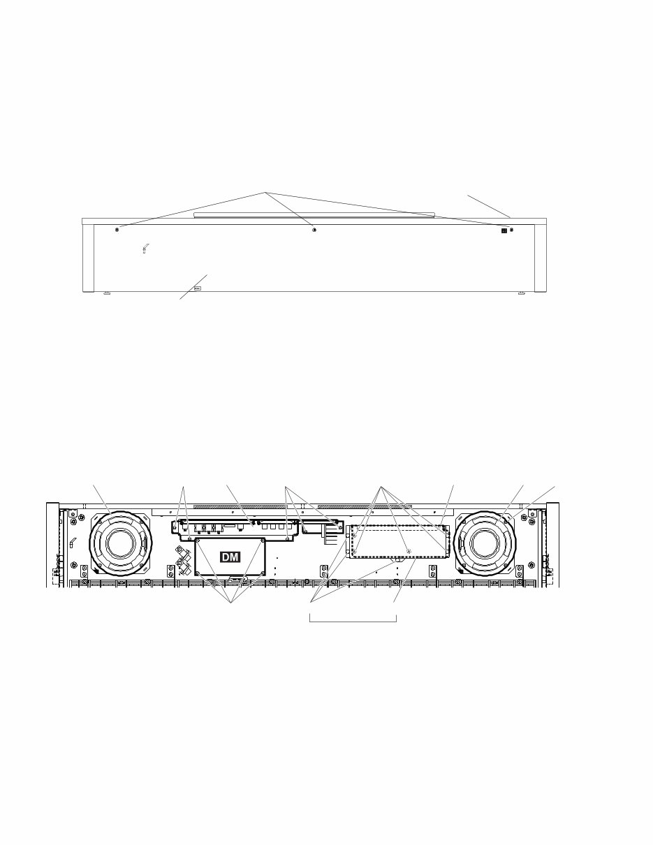
8 CLP-120 ■ DISASSEMBLY PROCEDURE 1. Top Board Assembly (Time required: about 2 min) * Before disassembling the top board assembly, shut up the key cover assembly completely to protect the key cover assembly from being scratched. 1-1. Remove the three (3) screws marked [48]. (Fig.1) 1-2. Slide the top board assembly forward and lift it out. [48] Top Board Assembly Back Top Board Assembly (Fig.1) [48]: Truss Head Screw 4.0X16 MFZN2BL (V6207400) 2. Circuit Boards or Units in the Main Unit (Time required: about 4 min for each) 2-1. Remove the top board assembly. (See Procedure 1) 2-2. Remove the following screws to remove each unit. (Fig.2) (Fig.2) Speaker (R) Speaker (L) [49] [40a] [40b] [40b] [40a] [47] Power Supply Unit Power Supply Unit Cover Only U.S.A model Jack Unit [47]: Bind Head Tapping Screw-B 3.0X8 MFZN2Y (EP600190) [40a]: Bind Head Tapping Screw-1 3.5X12 MFZN2Y (EP030240) [40b]: Bind Head Tapping Screw-1 3.5X12 MFZN2Y (EP030240) [49]: Truss Head Tapping Screw-1 4X20 MFZN2Y (20338800)
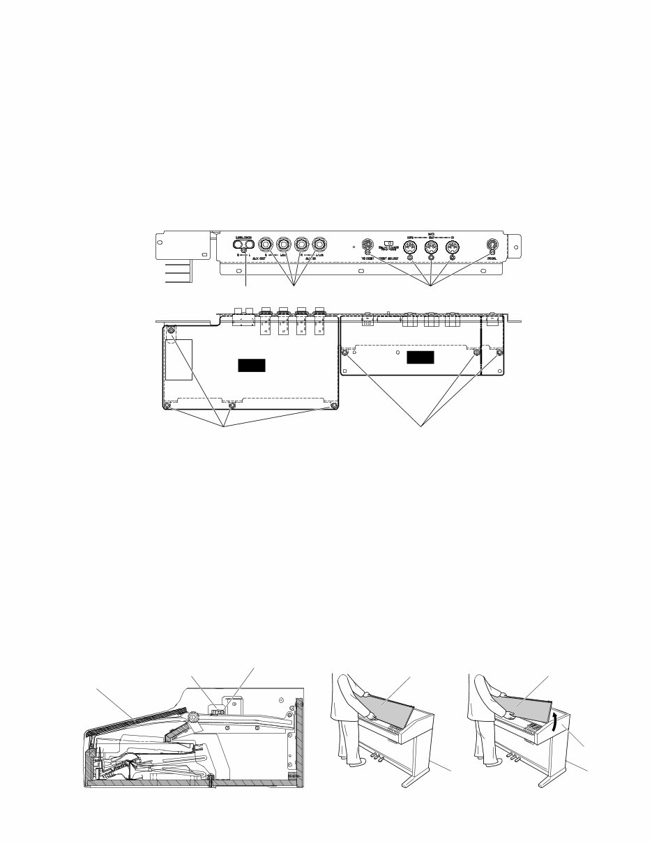
9 CLP-120 3. DJK Circuit Board (Time required: about 5 min) 3-1. Remove the top board assembly. (See Procedure 1) 3-2. Remove the jack unit. (See Procedure 2) 3-3. Remove the eight (8) screws marked [4a]. The DJK circuit board can then be removed. (Fig.3) 4. MAJ Circuit Board (Time required: about 5 min) 4-1. Remove the top board assembly. (See Procedure 1) 4-2. Remove the jack unit. (See Procedure 2) 4-3. Remove the five (5) screws marked [4b] and the four (4) hexagonal nuts marked [5]. The MAJ circuit board can then be removed. (Fig.3) MAJ DJK [4a] [4b] [4a] [4b] [5] 5. Key Cover Assembly (Time required: about 3 min) 5-1. Remove the top board assembly. (See Procedure 1) 5-2. Remove the screw marked [47] for each side, and then remove the rack cover L, R. (Fig.4-1) 5-3. Set the both ends of the rod to slits of the rack, and lift the key cover assembly. (Fig.4-2) 5-4. Lean the key cover assembly slightly, and then remove the guide pins from the guide rail one by one. (Fig.4-2) On these occations, take care not to scratch the side cover. When reinstall the key cover assembly, apply masking tape along the guide rail to protect the side covers from being scratched. (Fig.3) [4a]: Bind Head Tapping Screw-B 3.0X8 MFZN2BL (EP600190) [4b]: Bind Head Tapping Screw-B 3.0X8 MFZN2BL (EP600190) [5]: Hexagonal Nut 12.0 14X2 NFZN2BL (VB508600) [47] Rack Cover Keycover Assembly Key Cover Assembly Key Cover Assembly Side Cover (Fig.4-1) [47]: Bind Head Tapping Screw-B 3.0X8 MFZN2Y (EP600190) (Fig.4-2)
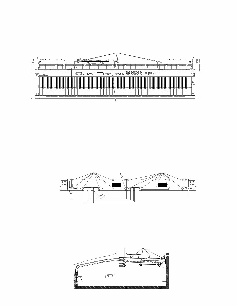
10 CLP-120 6. Panel Assembly (Time required: about 5 min) 6-1. Remove the top board assembly. (See Procedure 1) 6-2. Remove the key cover assembly. (See Procedure 5) 6-3. Remove the two (2) screws marked [51] and the six (6) screws marked [40]. The panel assembly can then be removed. (Fig.5) U H E A H U A A A A A [51] [51] [40] Control Panel Assembly (Fig.5) [40]: Bind Head Tapping Screw-1 3.5X12 MFZN2Y (EP030240) [51]: Bind Head Tapping Screw-B 4.0X10 MFZN2Y (EP640130) 7. PNL, PNR Circuit Board (Time required: about 7 min for each) 7-1. Remove the top board assembly. (See Procedure 1) 7-2. Remove the key cover assembly. (See Procedure 5) 7-3. Remove the panel assembly. (See Procedure 6) 7-4. Remove the eight (8) screws marked [24a] and the two (2) screws marked [27]. The PNL circuit board can then be removed. (Fig.6) 7-5. Remove the ten (10) screws marked [24b] . The PNR circuit board can then be removed. (Fig.6) A A A A A A A A A A A A A A A A A A B B A A A A [24a] [24b] [27] PNL PNR (Fig.6) [24a]: Bind Head Tapping Screw-B 3.0X8 MFZN2Y (EP600250) [24b]: Bind Head Tapping Screw-B 3.0X8 MFZN2Y (EP600250) [27]: Bind Head Tapping Screw-B 3.0X10 MFZN2BL (EP600140) 8. Rack Assembly L, R (Time required: about 4 min for each) 8-1. Remove the top board assembly. (See Procedure 1) 8-2. Remove the key cover assembly. (See Procedure 5) 8-3. Remove the four (4) screws marked [8] for each side. The rack assembly L, R can then be removed. (Fig.7) [8] Rack Assembly (Fig.7) [8]: Bind Head Tapping Screw-1 3.5X16 MFZN2Y (EP030190)
Are you experiencing issues with your Yamaha CLP120 Piano? Why spend a lot on repairs or replacements when you can easily do it yourself? This comprehensive service and repair manual is utilized by Official Certified Yamaha Technicians and is designed to assist you in troubleshooting and fixing your piano.
Specifications
Panel Layout
Circuit Board Layout
Block Diagram
Disassembly Procedure
LSI Pin Description
IC Block Diagram
Circuit Boards
Inspection
MIDI Implementation Chart
Overall Circuit Diagram
Parts List
This service manual contains detailed instructions, accompanied by pictures, to guide you through the repair and servicing process effectively. It is an official manual in .PDF format, ensuring high-resolution quality for printing.
Gain instant access to the manual after payment, eliminating shipping delays. The manual is available in English and compatible with both Windows and MAC platforms. With 76 pages of valuable information, this manual is an essential resource for professional mechanics and DIY enthusiasts alike.
If you are unable to find a specific service manual, feel free to reach out to us. With one of the largest service manual databases, we may be able to fulfill your request.
Recently Viewed
5,521,897Happy Clients
2,594,462eManuals
1,120,453Trusted Sellers
15Years in Business
Price:
Actual Price:
Yamaha Clavinova CLP-120 Piano Service Manual & Repair Guide