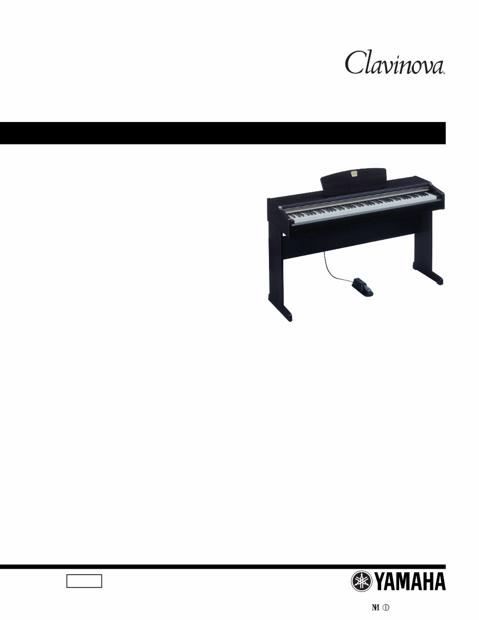
Yamaha Clavinova CLP-110 Piano Service Manual & Repair Guide
What's Included?
Lifetime Access
Fast Download Speeds
Online & Offline Access
Access PDF Contents & Bookmarks
Full Search Facility
Print one or all pages of your manual
SERVICE MANUAL HAMAMATSU, JAPAN 1.27K-389 Printed in Japan ’02, 06 CL 001675 ■ CONTENTS SPECIFICATIONS .............................................................................. 3 PANEL LAYOUT .................................................................................. 4 CIRCUIT BOARD LAYOUT ................................................................. 5 BLOCK DIAGRAM .............................................................................. 6 DISASSEMBLY PROCEDURE ........................................................... 7 LSI PIN DESCRIPTION .................................................................... 14 IC BLOCK DIAGRAM ........................................................................ 16 CIRCUIT BOARDS ........................................................................... 17 INSPECTION .................................................................................... 24 MIDI IMPLEMENTATION CHART ..................................................... 26 OVERALL CIRCUIT DIAGRAM PARTS LIST This document is printed on chlorine free (ECF) paper with soy ink. CLP-110 CLP-110
2 CLP-110 IMPORTANT NOTICE This manual has been provided for the use of authorized Yamaha Retailers and their service personnel. It has been assumed that basic service procedures inherent to the industry, and more specifically Yamaha Products, are already known and understood by the users, and have therefore not been restated. WARNING: Failure to follow appropriate service and safety procedures when servicing this product may result in per- sonal injury, destruction of expensive components and failure of the product to perform as specified. For these reasons, we advise all Yamaha product owners that all service required should be performed by an authorized Yamaha Retailer or the appointed service representative. IMPORTANT: This presentation or sale of this manual to any individual or firm does not constitute authorization, certifica- tion, recognition of any applicable technical capabilities, or establish a principal-agent relationship of any form. The data provided is believed to be accurate and applicable to the unit(s) indicated on the cover. The research engineering, and service departments of Yamaha are continually striving to improve Yamaha products. Modifications are, therefore, inevitable and changes in specification are subject to change without notice or obligation to retrofit. Should any discrepancy appear to exist, please contact the distributor's Service Division. WARNING: Static discharges can destroy expensive components. Discharge any static electricity your body may have accumulated by grounding yourself to the ground bus in the unit (heavy gauge black wires connect to this bus). IMPORTANT: Turn the unit OFF during disassembly and parts replacement. Recheck all work before you apply power to the unit. WARNING: CHEMICAL CONTENT NOTICE! The solder used in the production of this product contains LEAD. In addition, other electrical / electronic and / or plastic (where applicable) components may also contain traces of chemicals found by the California Health and Welfare Agency (and possibly other entities) to cause cancer and / or birth defects or other reproductive harm. DO NOT PLACE SOLDER, ELECTRICAL / ELECTRONIC OR PLASTIC COMPONENTS IN YOUR MOUTH FOR ANY REASON WHAT SO EVER! Avoid prolonged, unprotected contact between solder and your skin! When soldering, do not inhale solder fumes or expose eyes to solder / flux vapor! If you come in contact with solder or components located inside the enclosure of this product, wash your hands before handling food. ■ WARNING Components having special characteristics are marked and must be replaced with parts having specification equal to those originally installed. • This applies only to products distributed by Yamaha-Kemble Music (U.K.) Ltd. IMPORTANT NOTICE FOR THE UNITED KINGDOM Connecting the Plug and Cord IMPORTANT. The wires in this mains lead are coloured in accordance with the following code: BLUE : NEUTRAL BROWN : LIVE As the colours of the wires in the mains lead of this apparatus may not correspond with the coloured makings identifying the terminals in your plug proceed as follows: The wire which is coloured BLUE must be connected to the terminal which is marked with the letter N or coloured BLACK. The wire which is coloured BROWN must be connected to the terminal which is marked with the letter L or coloured RED. Making sure that neither core is connected to the earth terminal of the three pin plug. (2 wires)
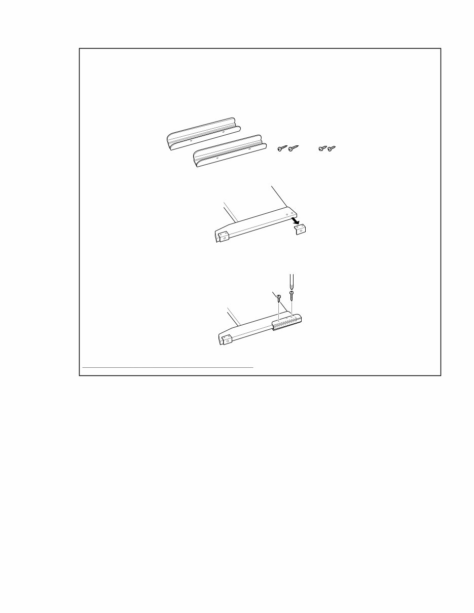
3 CLP-110 ATTACHING THE KEYBOARD STAND STABILIZERS (U Only) IMPORTANT! Be sure to attach the stabilizers to the keyboard stand prior to use to ensure maximum stability. Be sure to attach the stabilizers to the keyboard stand feet prior to assembly of the keyboard stand. 1. Make sure that you have two stabilizers and four screws (one stabilizer for each of the keyboard stand feet and one 3.5X20mm screw and one 3.5X14mm screw for each of the stabilizers). ■ SPECIFICATIONS Keyboard 88 keys (A-1 - C7) Sound Source AWM Stereo Sampling Polyphony 32 Notes Max. Voice Selection 10 Effect Reverb Volume Master Volume Controls Dual, Metronome, Transpose Pedal Damper Demo Songs 10 voice Demo Songs, 50 preset Songs Jacks/Connectors MIDI (IN/OUT/THRU), PHONES x 2, DAMPER PEDAL Main Amplifiers 20W x 2 Speakers Oval (12cm x 6cm) x 2 Power Consumption 48W Dimensions (W x D x H) 1345mm x 426mm x 814mm [52-15/16" x 16-3/4" x 32-1/2"] (with music stand) 1345mm x 426mm x 967mm [52-15/16" x 16-3/4" x 38-11/16"] Weight 36kg (79lbs. 6oz) Accessories Owner’s Manual, “50 greats for the Piano” (Music Book), Bench (included or optional depending on locale), Quick Operation Guide, Damper Pedal 3.5X20mm screws 3.5X14mm screws 2. Remove the anti-skid bracket from the rear side of the keyboard stand feet. Keep the anti-skid bracket and screws for future use. 3. Position the stabilizer on the keyboard stand foot so the rear of the stabilizer extends beyond the end of the foot. Align the rear foot hole with the rear stabilizer hole. Insert and tighten one of the 3.5X20mm screws. Then insert one of the 3.5X14mm screw in the front hole, and tighten it. Tighten the screw very firmly since there is no front screw hole on the feet. See the illustration below. Do not slide the unit on the floor with the stabilizers attached to the feet. Otherwise, the floor will be scratched. MAKE SURE THA T ALL SCREWS ARE TIGHTNED FIRML Y .
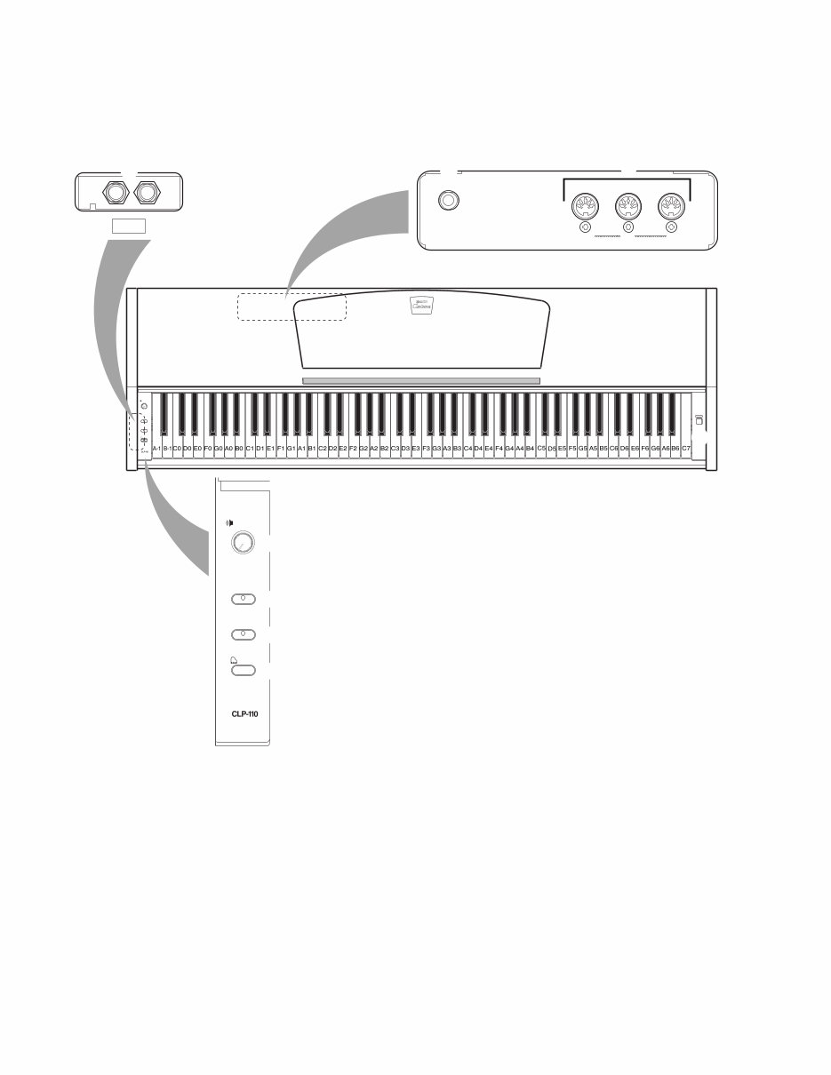
4 CLP-110 ■ PANEL LAYOUT ● Top Panel MASTER VOLUME DEMO METRONOME VOICE POWER MIDI DAMPER PEDAL IN OUT THRU PHONES MASTER VOLUME DEMO METRONOME VOICE MIN MAX [POWER] button [MASTER VOLUME] control [DEMO] button [METRONOME] button [VOICE] button [PHONES] jack [DAMPER PEDAL] jack MIDI [IN] [OUT] [THRU] connector
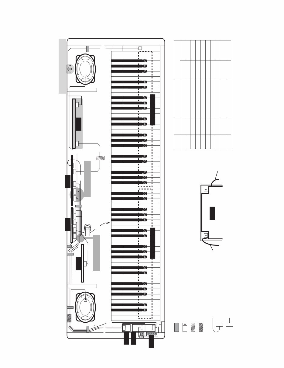
5 CLP-110 ■ CIRCUIT BOARD LAYOUT 2NC-V851290 (V004510) (V909110) (V908680) DM-CN1 PN-CN001 PS-CN2 AM-CN1 AM-CN2 DM-CN5 AM-CN3 AM-CN4 DM-CN2 DM-CN3 D-JACK-CN1 DM-CN4 AEXL88L-CN1 VK099600 HP-CN2 PL-CN1 HP-CN1 SP Lch WH/BL SP Rch RE/BL (VK10860) (V908650) V9401000 (V908660) VS353700 POWER SW PS-CN1 (V909180) AM-CN5 VR-CN002 PL P.SW CN1 CN1 CN1 CN2 : Code Binder : Filament Tape (12 x 50) : Ferrite Core : Connector Direction AMSP Wire Harness AMHP Wire Harness PSAM Wire Harness MK Wire Harness KRD-KRD Wire Harness Part Number KRD-KRD Wire Harness KRD-KRD Wire Harness PSW Wire Harness KRD-KRD Wire Harness VOL Wire Harness Part Name Location Destination Rear view of PS unit NOTE.: , wire harness shall be around as the following drawing .(U/C model only) CN1 CN2 DM D-JACK VR PN HP AM PS PS CN5 CN4 CN1 CN3 CN2 CN3 CN4 CN5 CN2 CN2 CN1 CN1 GH-D_SW L GH-D_SW H Wire harness don’t touch the key cover. Wire harness don’t touch the heat sink. Wire is looped. And fix it to don’t touch the speaker. to GH-D_SW L-CN1 ! NOTE ! : Aluminum Tape (40 x 50)
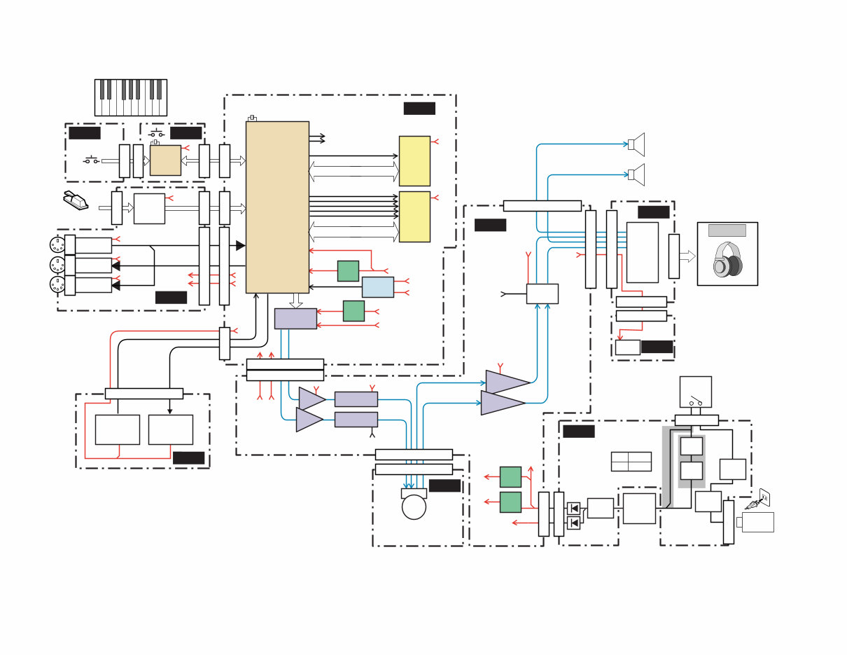
6 CLP-110 ■ BLOCK DIAGRAM PHONES x 2 1 1N 2 UC, E 2 LSIIC MUTE +B CS0 8.4672MHz DATA BUS,ADDRESS BUS SMA(0-21),SMD(0-15) CRD CWE DATA BUS,ADDRESS BUS CMA(0-16),CMD(0-15) CUB CLB CS1 AC CORD +B +5D 4MHz Full Range SPEAKERS L R PEDAL +12V MASTER +5D 12 x 6 cm 4 Ω 20W 12 x 6 cm 4 Ω 20W MUTE +5D +12V +12V +12V +12V +15V +15V +12V +5D +5D VOLUME DM VR AM HP PL PS PN D-JACK GH-D_SWL GH-D_SWH KSN2 PEDAL IN MIDI IN MIDI OUT MIDI THRU SWX00B DAC (18bit) +5v REG +5v REG +12V +12v REG +3.3v REG INITIAL CLEAR 1M SRAM 64M ROM (PRG/WAVE) SW LED EQUALIZER EQUALIZER POWER AMP MUTING RELAY HEAD PHONES JACK P.L F3 FUSE VOLTAGE SELECTOR F2 FUSE F1 FUSE LINE FILTER TRANS- FORMER POWER SW KEYBOARD 88KEY +5D +3.3D +3.3D +5D +5D +5D +12V +12V +5D +5D +5D +3.3D +5D +5D +3.3D +3.3D CN5-11P CN2-11P CN1-7P CN5-8P CN2-8P CN1-2P CN2-2P CN3-4P CN4-7P CN3-8P CN1-10P CN1-5P CN2-5P CN1-7P CN1-10P CN4-8P CN1-8P CN2, 3 CN1, 2 JK6 CN2-5P HP1, 2 AC-INLET CN1-3P CN1-7P 21,124,154,155 15 1 145-147 128,129 158, 159 4,7,12,18,49,61,77, 91,148 35,119,133, 143,161 81-87,89, 96-99,102-118, 121-123 95 90 101 93 88 23-34,37-40, 47,48,51-59, 62-72 46 132 124 IC1-168P 1-11,15-22, 24-31,34-44 1-5,7-10, 13-16,18-21, 24-27,29-32, 35-38,42-44 12 11,33 39 40 41 17 6 11 6 14-15 4 7,8 2 8 14 14 1 6 7 1,3,5,7,9,11 1,3,5,7,9,11 13 13 2 15,16 10,17 7 11,12 JK1 JK2 JK3 IC3-44P IC10-44P IC7 IC8 IC7 IC5 IC3 IC3 DB1 D1, D2 RY2 VR1 IC4 IC7 IC9,TR1,TR2 IC4-16P 9 10 153 20 Lch Lch Rch Rch Primary Secondary *1: N *2: UC, E
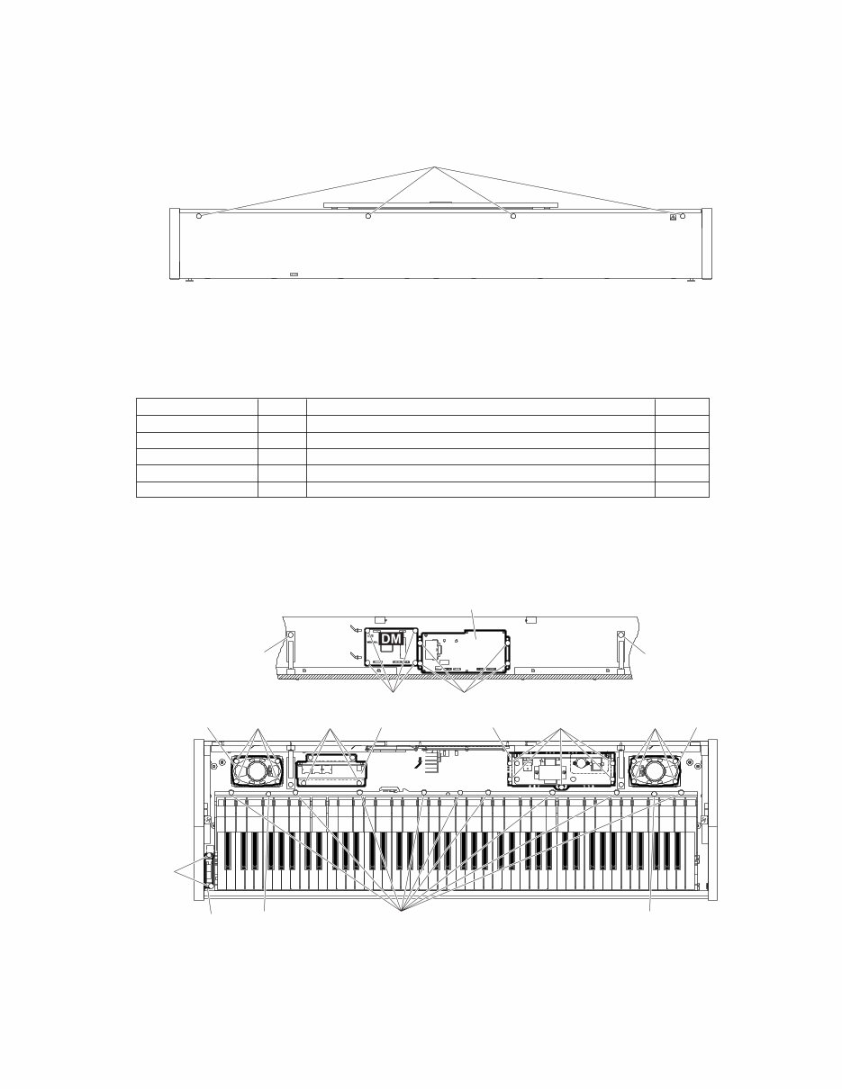
7 CLP-110 ■ DISASSEMBLY PROCEDURE (Fig.1) [14]: Truss Head Tapping Screw-1 4.0X25 MFZN2BL (EN640160) (Fig.2) 1. Top Board Assembly (Time required: about 1 min) 1-1 Remove the four (4) screws marked [14]. (Fig.1) 1-2 Slide the top board assembly forward and lift it out. [14] F F F F [40c] [10] [31] [23] [4] [3] [4] [23] M M A A T T K K K K A A A A P P P J A A A B B J D D D D [10] [40b] [103] M M M M P P P P P D D D D [40a] M M M M Jack Assembly Speaker (L) D-Jack Assembly Power Supply Unit AM Sheet Assembly Speaker (R) 2. Circuit Boards or Units in the Main Unit (Time required: about 6 min) 2-1 Remove the top board assembly. (See procedure 1) 2-2 Remove the following screws to remove each circuit board or unit. (Fig.2) Circuit Board or Unit Ref No. Screw Quantity DM 31 Bind Head Tapping Screw-B 3.0X6 MFZN2Y (EP600130) 4 AM Sheet Assembly 40a Bind Head Tapping Screw-1 3.5X12 MFZN2Y (EP030240) 4 D-JACK Assembly 40b Bind Head Tapping Screw-1 3.5X12 MFZN2Y (EP030240) 4 Power Supply Unit 103 Bind Head Tapping Screw-1 3.5X12 MFZN2Y (EP030240) 5 Speaker L, R 10 Truss Head Tapping Screw-1 4.0X16 MFZN2Y (03747340) 8 * To remove the DM circuit board or AM sheet assembly, use a screw driver which is shorter than a clearance between the circuit board and the keyboard assembly. In using a longer screw driver by necessity, remove the keyboard assembly before removing these circuit boards. (See procedure 8) * In connecting the speaker cables again, take care of polarity. L ch: + (white), - (black) R ch: + (red), - (black) [3]: Pan Head Screw 5.0X25 MFZN2Y PW (VV040700) [4]: Bind Head Tapping Screw-1 4.0X14 MFZN2Y (EP040230) [10]: Truss Head Tapping Screw-1 4.0X16 MFZN2Y (03747340) [23]: Truss Head Tapping Screw-1 3.5X20 MFZN2Y (EN630260) [31]: Bind Head Tapping Screw-B 3.0X6 MFZN2Y (EP600130) [40]: Bind Head Tapping Screw-1 3.5X12 MFZN2Y (EP030240) [103]: Bind Head Tapping Screw-1 3.5X12 MFZN2Y (EP030240)
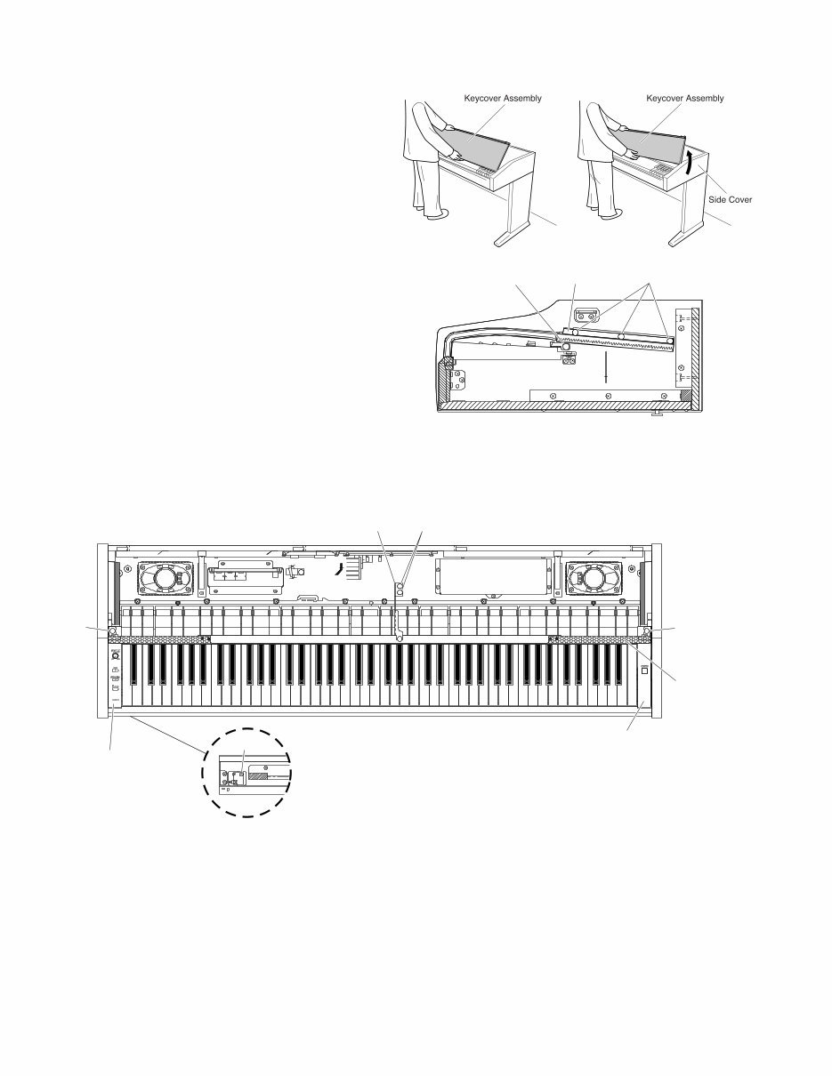
8 CLP-110 (Fig.3) (Fig.4) [7]: Bind Head Tapping Screw-1 3.5X20 MFZN2Y (EP030470) [40]: Bind Head Tapping Screw-1 3.5X12 MFZN2Y (EP030240) (Fig.5) 3. Key Cover Assembly (Time required: about 1 min) 3-1 Remove the top board assembly. (See procedure 1) 3-2 Cover the keyboards completely with the key cover assembly, and lift up the rear of it. (Fig.3) 3-3 Lean the key cover assembly slightly and remove the guide pin from the guide rail. (Fig.3) * Don’t lean the key cover too much not to let the sash F scratch the front rail. 4. End Block Assembly (L, R) (Time required: about 3 min) 4-1 Remove the top board assembly. (See procedure 1) 4-2 Remove the key cover assembly. (See procedure 3) 4-3 Remove the two (2) screws marked [40] to remove the angle Z. (Fig.5) 4-4 Remove the screw marked [40] for each side to remove the panel assembly. (Fig.4) 4-5 Remove the three (3) screws marked [7] for each side to remove the rack (L, R). (Fig.4) 4-6 Remove the screw marked [12] for each side. The end block assembly (L, R) can then be removed. (Fig.5) [7] [40] C C C M Rack Assembly [40] [12] [T2f] [12] M E E L M H Angle Z End Block Assembly (L) End Block Assembly (R) Panel Assembly [T2f]: Bind Head Tapping Screw-1 3.5X12 MFZN2Y (EP030240) [12]: Bind Head Tapping Screw-B 4.0X10 MFZN2Y (EP640130) [40]: Bind Head Tapping Screw-1 3.5X12 MFZN2Y (EP030240)
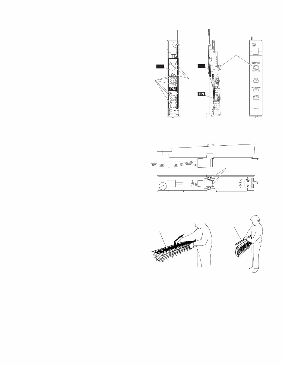
9 CLP-110 (Fig.8) 5. PN and VR Circuit Board (Time required: about 5 min) 5-1 Remove the top board assembly. (See procedure 1) 5-2 Remove the key cover assembly. (See procedure 3) 5-3 Remove the end block assembly L. (See procedure 4) 5-4 Remove the nine (9) screws marked [8]. (Fig.6) 5-5 Remove the VR knob marked [7]. The PN circuit board can then be removed. (Fig.6) * When removing the VR circuit board alone, remove the three (3) screws marked [8a]. (Fig.6) The PN circuit board can not be removed without removing the VR circuit board. 6. Power Switch Assembly (Time required: about 5 min) 6-1 Remove the top board assembly. (See procedure 1) 6-2 Remove the key cover assembly. (See procedure 3) 6-3 Remove the end block assembly R. (See procedure 4) 6-4 Remove the two (2) screws marked [30]. The power switch assembly can then be removed. (Fig.7) 7. Headphones Jack Assembly (Time required: about 4 min) 7-1 Remove the top board assembly. (See procedure 1) 7-2 Remove the key cover assembly. (See procedure 3) 7-3 Remove the end block assembly L. (See procedure 4) 7-4 Remove the two (2) screws marked [40c]. The headphones jack assembly can then be removed. (Fig.2) 8. Keyboard Assembly (Time required: about 7 min) 8-1 Remove the top board assembly. (See procedure 1) 8-2 Remove the key cover assembly. (See procedure 3) 8-3 Remove the end block assembly (L, R). (See procedure 4) 8-4 Remove the two (2) screws marked [40] to remove the angle Z. (Fig.5) 8-5 Remove the screw marked [40] for each side to remove the panel assembly. (Fig.4) 8-6 Remove the nine (9) screws marked [3] and the two (2) screws marked [4]. (Fig.2) 8-7 Move the keyboard assembly backward, hold central area of it and get it upright to remove. (Fig.8) * It may twist and damage the frame to hold both side ends of keyboard assembly or remove it in a horizontal position. (Fig.6) [30] Keyboard assembly Keyboard assembly (Fig.7) [30]: Bind Head Tapping Screw-B 3.0X8 MFZN2Y (EP600250) [7]: Knob Black (V2300100) [8]: Bind Head Tapping Screw-B 3.0X8 MFZN2Y (EP600250) [8b] [8a] [7] VR VR
10 CLP-110 9. PL Circuit Board (Time required: about 7 min) 9-1 Remove the top board assembly. (See procedure 1) 9-2 Remove the key cover assembly. (See procedure 3) 9-3 Remove the end block assembly (L, R). (See procedure 4) 9-4 Remove the keyboard assembly. (See procedure 8) 9-5 Remove the screw marked [T2f]. The PL circuit board can then be removed. (Fig.5) 10. Back Top Board Assembly (Time required: about 5 min) 10-1 Remove the top board assembly. (See procedure 1) 10-2 Remove the screw marked [23] for each side. (Fig.2) 10-3 Remove the six (6) screws marked [T9a] and the two (2) screws marked [T9b] for each side. The back top board assembly can then be removed. (Fig.9) [T5] [T9a] [T9c] [T9c] [T9b] Side Cover Assembly (L) Side Cover Assembly (R) Back Top Panel Assembly 11. Main Unit (Time required: about 2 min) * For safety, this process should be done by two personnel. * Previously, spread soft cloth on where the main unit will be laid after it is removed. * In removing the main unit, take great care not to catch fingers between the main unit and the stand. 11-1 Remove the two (2) screws marked [S1] for each side. (Fig.10) 11-2 Move the main unit backward and lift it out. (Fig.10) (Fig.9) [T5]: Bind Head Tapping Screw-1 3.5X16 MFZN2Y (EP030190) [T9]: Truss Head Tapping Screw-1 3.5X25 MFZN2Y (EN630080) [S1] x 4 (Fig.10) [S1]: Bind Head Screw 6.0X16 MFZN2BL (EG360020)
Are you experiencing issues with your Yamaha Piano? Why spend a lot on repairs or replacements when you can handle it yourself? This comprehensive service and repair manual is utilized by certified Yamaha technicians and will assist you in troubleshooting and fixing your piano.
Specifications
Panel Layout
Circuit Board Layout
Block Diagram
Disassembly Procedure
LSI Pin Description
IC Block Diagram
Circuit Boards
Inspection
MIDI Implementation Chart
Overall Circuit Diagram
Parts List
This detailed service manual includes high-resolution images and step-by-step instructions for the best repair and servicing methods. It is the official manual, not a scanned or bootlegged copy, ensuring high-quality printed pages.
Gain instant access after payment with no shipping fees or waiting for postal delivery, allowing you to commence repairs immediately. The manual is available in English and is compatible with Windows and MAC platforms, comprising 57 pages.
If you are unable to find a specific service manual, feel free to reach out to us. With one of the largest service manual databases, we have a good chance of fulfilling your request.
Recently Viewed
5,521,897Happy Clients
2,594,462eManuals
1,120,453Trusted Sellers
15Years in Business
Price:
Actual Price:
Yamaha Clavinova CLP-110 Piano Service Manual & Repair Guide