

SERVICE MANUAL
SPECIFICATIONS (総合仕様) .................................................................. 3/4
PANEL LAYOUT (パネルレイアウト) ......................................................... 5
CIRCUIT BOARD LAYOUT & WIRING (ユニットレイアウト&結線図) ........ 7
BLOCK DIAGRAM (ブロックダイアグラム) .............................................. 8
DISASSEMBLY PROCEDURES (分解手順) ............................................... 9
LSI PIN DESCRIPTION (LSI端子機能表) .................................................. 15
IC BLOCK DIAGRAM (ICブロック図) ...................................................... 16
CIRCUIT BOARDS (シート基板図) ........................................................... 17
TEST PROGRAM (テストプログラム) ................................................ 20/22
MIDI IMPLEMENTATION CHART
(MIDIインプリメンテーションチャート) ............................................. 24/25
MIDI DATA FORMAT ................................................................................. 26
PARTS LIST
OVERALL CIRCUIT DIAGRAM (総回路図)
■ CONTENTS (目次)
PK 001775
Copyright (c) Yamaha Corporation. All rights reserved. 07.04
HAMAMATSU, JAPAN
PSR-E213: 200702-xxxxxx
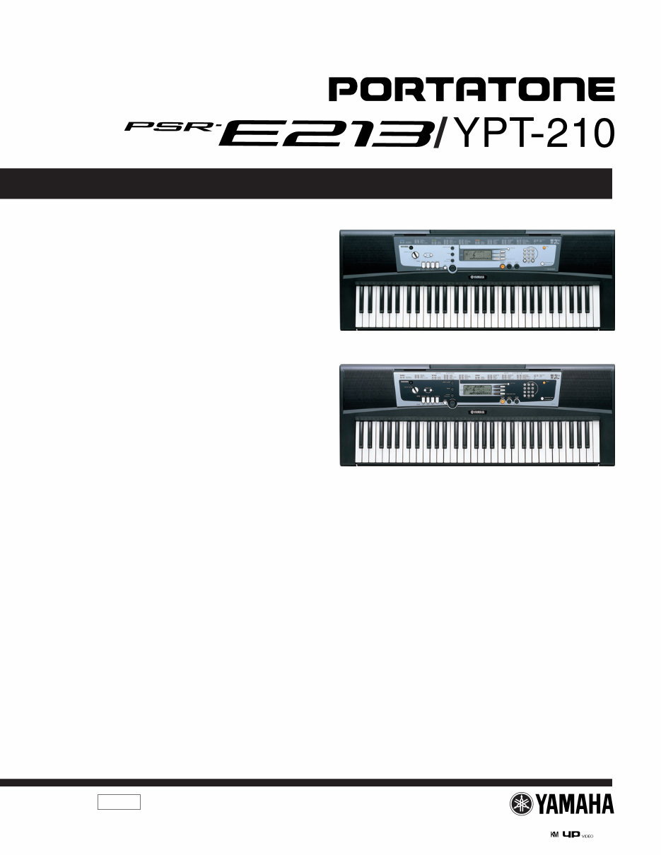
PSR-E213
YPT-210
* YPT-210 is an overseas export model. (YPT-210は、輸出専用モデルです。)
PSR-E213/YPT-210
2
■ WARNING
Components having special characteristics are marked and must be replaced with parts having specification equal to those originally
installed.
印の部品は、安全を維持するために重要な部品です。交換する場合は、安全のために必ず指定の部品をご使用ください。
IMPORTANT NOTICE
This manual has been provided for the use of authorized Yamaha Retailers and their service personnel. It has been assumed that basic service
procedures inherent to the industry, and more specifically Yamaha Products, are already known and understood by the users, and have
therefore not been restated.
WARNING: Failure to follow appropriate service and safety procedures when servicing this product may result in personal injury, destruc-
tion of expensive components and failure of the product to perform as specified. For these reasons, we advise all Yamaha
product owners that all service required should be performed by an authorized Yamaha Retailer or the appointed service
representative.
IMPORTANT: This presentation or sale of this manual to any individual or firm does not constitute authorization, certification, recognition of
any applicable technical capabilities, or establish a principal-agent relationship of any form.
The data provided is believed to be accurate and applicable to the unit(s) indicated on the cover. The research engineering, and service
departments of Yamaha are continually striving to improve Yamaha products. Modifications are, therefore, inevitable and changes in specifica-
tion are subject to change without notice or obligation to retrofit. Should any discrepancy appear to exist, please contact the distributor’s Service
Division.
WARNING: Static discharges can destroy expensive components. Discharge any static electricity your body may have accumulated by
grounding yourself to the ground bus in the unit (heavy gauge black wires connect to this bus).
IMPORTANT: Turn the unit OFF during disassembly and parts replacement. Recheck all work before you apply power to the unit.
WARNING: CHEMICAL CONTENT NOTICE!
The solder used in the production of this product contains LEAD. In addition, other electrical/electronic and/or plastic (Where applicable)
components may also contain traces of chemicals found by the California Health and Welfare Agency (and possibly other entities) to cause
cancer and/or birth defects or other reproductive harm.
DO NOT PLACE SOLDER, ELECTRICAL/ELECTRONIC OR PLASTIC COMPONENTS IN YOUR MOUTH FOR ANY REASON WHAT SO
EVER!
Avoid prolonged, unprotected contact between solder and your skin! When soldering, do not inhale solder fumes or expose eyes to solder/flux
vapor!
If you come in contact with solder or components located inside the enclosure of this product, wash your hands before handling food.
PSR-E213/YPT-210
3
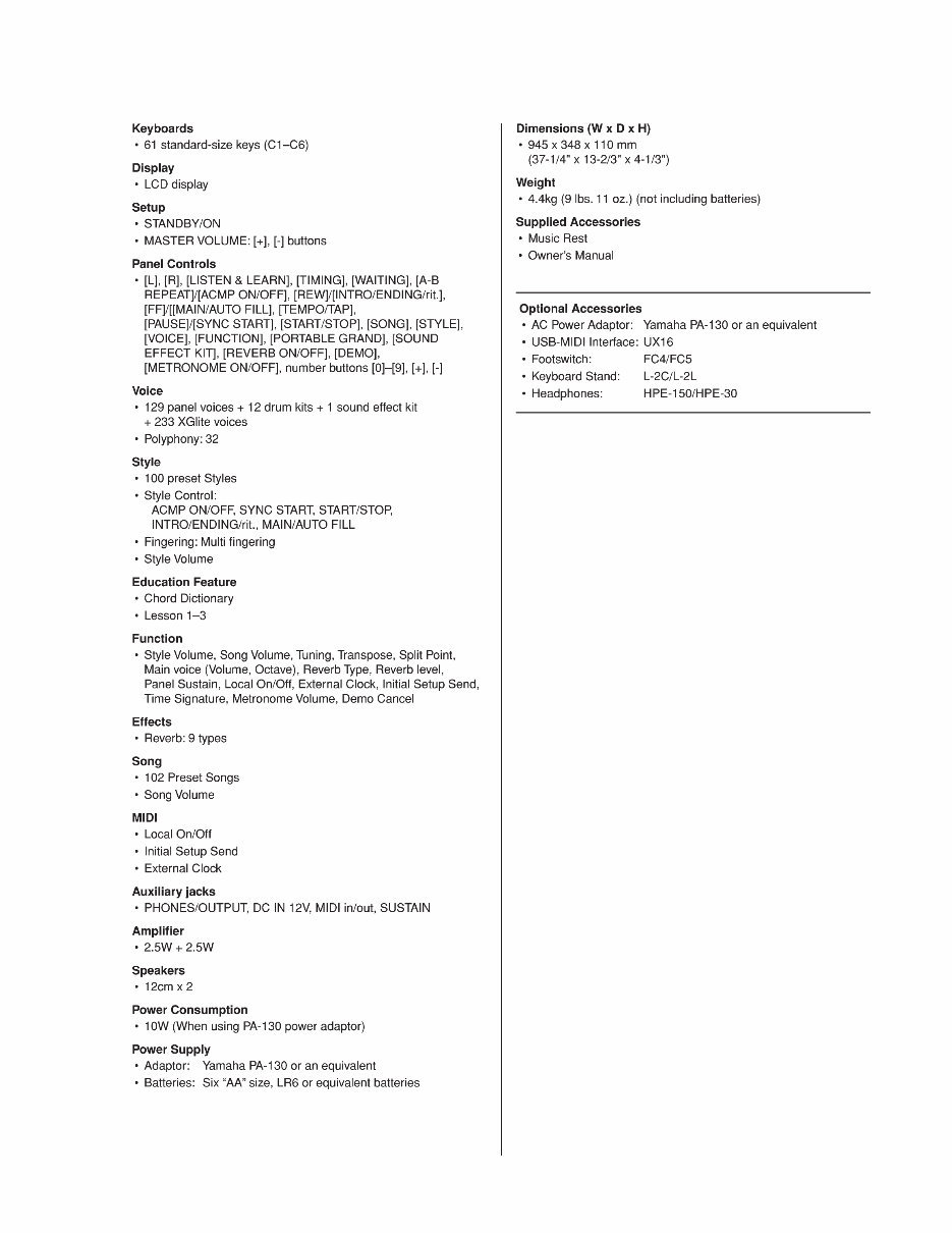
■ SPECIFICATIONS
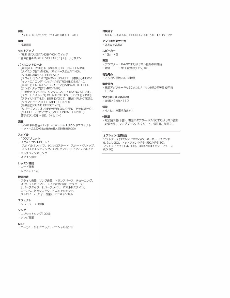
PSR-E213/YPT-210
4
■ 総合仕様
PSR-E213/YPT-210
5
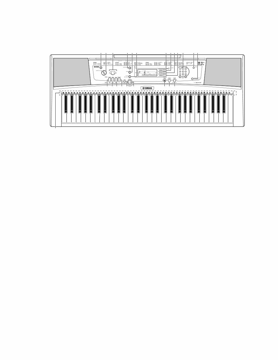
■ PANEL LAYOUT (パネルレイアウト)
• Front panel (フロントパネル)
[STANDBY/ON] switch
[MASTER VOLUME]
[+] button
[-] button
LESSON PART
[L] button
[R] button
[LISTEN & LEARN] button
[TIMING] button
[WAITING] button
[FUNCTION] button
[SONG] button
[STYLE] button
[VOICE] button
Number buttons [0] – [9], [+], [-]
[DEMO] button
[METRONOME ON/OFF] button
[A-B REPEAT] button
[ACMP ON/OFF] button
[REW] button
[INTRO/ENDING/rit] button
[FF] button
[MAIN/AUTO FILL] button
[TEMPO/TAP] button
[PAUSE] button
[SYNC START] button
[START/STOP] button
[PORTABLE GRAND] button
[SOUND EFFECT KIT] button
[REVERB ON/OFF] button
Drum Kit
1
2
3
4
5
6
7
8
9
0
A
B
C
D
E
F
G
H
I
J
K
L
M
1
2
3
4
5
6
7
8
9
0
A
B
C
D
E
F
G
H
I
J
K
L
M
[電源切/入] (STANDBY/ON)スイッチ
[全体音量] (MASTER VOLUME)
[+]ボタン
[-]ボタン
レッスンパート(LESSON PART)
[左手] (L)ボタン
[右手] (R)ボタン
[お手本] (LISTEN &LEARN)ボタン
[タイミング] (TIMING)ボタン
[マイペース] (WAITING)ボタン
[機能] (FUNCTION)ボタン
[ソング] (SONG)ボタン
[スタイル] (STYLE)ボタン
[楽器] (VOICE)ボタン
数字ボタン[0]~[9]、[+]、[-]
[デモ] (DEMO)ボタン
[メトロノームオン/オフ] (METRONOME ON/OFF)ボタン
[くり返し練習] (A-B REPEAT)ボタン
[スタイルオン/オフ] (ACMP ON/OFF)ボタン
[巻戻し] (REW)ボタン
[イントロ/エンディング/rit.] (INTRO/ENDING/rit.)ボタン
[早送り] (FF)ボタン
[メイン/フィルイン] (MAIN/AUTO FILL)ボタン
[テンポ/タップ] (TEMPO/TAP)ボタン
[一時停止] (PAUSE)ボタン
[シンクロスタート] (SYNC START)ボタン
[スタート/ストップ] (START/STOP)ボタン
[グランドピアノ] (PORTABLE GRAND)ボタン
[効果音] (SOUND EFFECT KIT)ボタン
[リバーブオン/オフ] (REVERB ON/OFF)ボタン
ドラムキット
GrandPno 001
001
1 456 2 3
M
D FGH I E JKL
B 890 C 7 A

PSR-E213/YPT-210
6
• Rear panel (リアパネル)
MIDI IN/OUT terminals
SUSTAIN jack
PHONES/OUTPUT jack
DC IN 12V jack
N
O
P
Q
N
O
P
Q
MIDI IN/OUT 端子
SUSTAIN(サステイン)端子
PHONES/OUTPUT(ヘッドフォン/外部出力)端子
DC IN 12V(電源アダプター)端子
N O P Q
PSR-E213/YPT-210
7
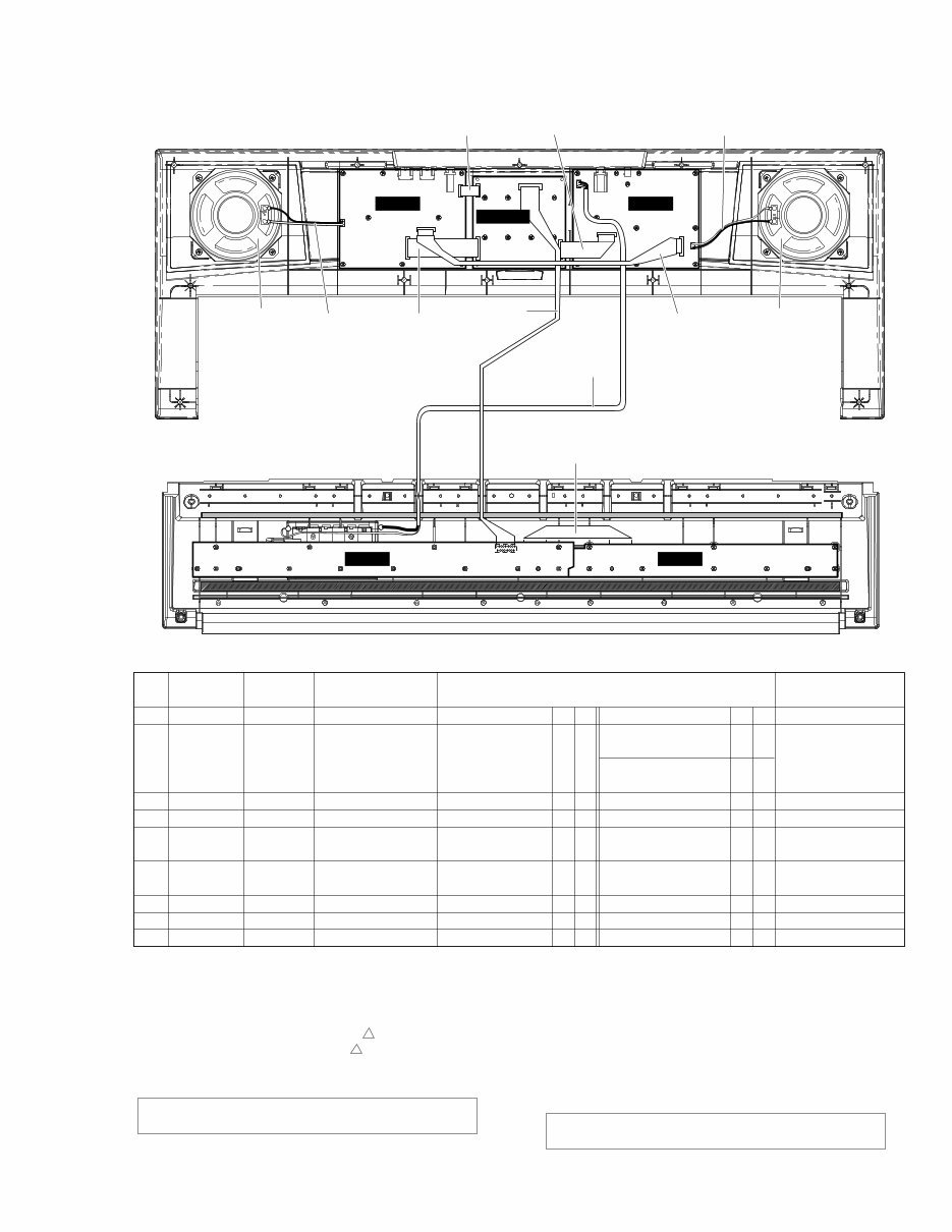
■ CIRCUIT BOARD LAYOUT & WIRING (ユニットレイアウト&結線図)
PNAM
2/2
PNAM
DMLCD 1/2
Speaker L
(スピーカL)�
w
• Upper case side (上ケース側)�
• Lower case side (下ケース側)�
*The parts with “( )” in “Part No.” are not available as spare parts.
*1: Installation
*2: Manual soldering
*3: Dip soldering
*4: Edge mark is adjusted to Pin 1 mark ( mark).
*6: Speaker (Red wire is connected to + terminal.)
*7: Battery terminal A (Black wire), Battery terminal B (Red wire).
Caution: Be sure to attach the removed filament tape just
as it was before removal.
*5: Red wire is adjusted to Pin 1 mark ( mark).
*部品番号が( )で囲まれている部品は、サービス部品として準備�
されていません。�
*1:差込み�
*2:手半田�
*3:ディップ�
*4:エッジマークが1ピン(△)側�
*6:スピーカ(赤色線材が+端子)�
*5:赤色線材が1ピン(△)側�
*7:接点バネA(黒)、接点バネB(赤)�
注意: 一度剥がしたフィラメントテープは、取り外す前と�
同じように、取り付けてください。�
Speaker R
(スピーカR)�
6 7
9
4
1
8 3 5
MK-L MK-H
+ +
– –
– –
+ +
Location
ロケーション�
Parts No.
部品番号� 束線名�
30
120
WH103
WH104
WH201
WH202
WH301
WH302
120c
*1
*1
*3
*3
*3
*3
*3
*3
*1
*4
*5
*4
*4
*5
*5
*4
*4
*4
*1
*2
*2
*1
*3
*2
*2
*1
*1
*1
*4
*7
*7
*4
*4
*6
*6
*4
*4
*4
1
2
3
4
9
8
7
6
5
MK
BATTERY
PN3
PN
SP
SP
PN4
PN1
MK
MK-L
PNAM1/2-CN101
PNAM1/2-CN103
PNAM1/2-CN104
PNAM1/2-CN201
PNAM2/2-CN202
PNAM2/2-CN301
PNAM2/2-CN302
MK-L
DMLCD-CN501
(接点バネA)�
Battery terminal A
(接点バネB)�
Battery terminal B
DMLCD-CN601
PNAM2/2-CN303
(スピーカL)�
(スピーカR)�
Speaker-L
Speaker-R
DMLCD-CN602
DMLCD-CN603
MK-H
17P
3P
10P
10P
2P
2P
12P
6P
11P
WE156400
(WE15510)
(WE15580)
(WE15550)
(WE67670)
(WE67670)
(WE15600)
(WE15560)
(V719030)
Connector Assembly
配線先�
Destination
備考�
Remarks
No.
PSR-E213/YPT-210
8
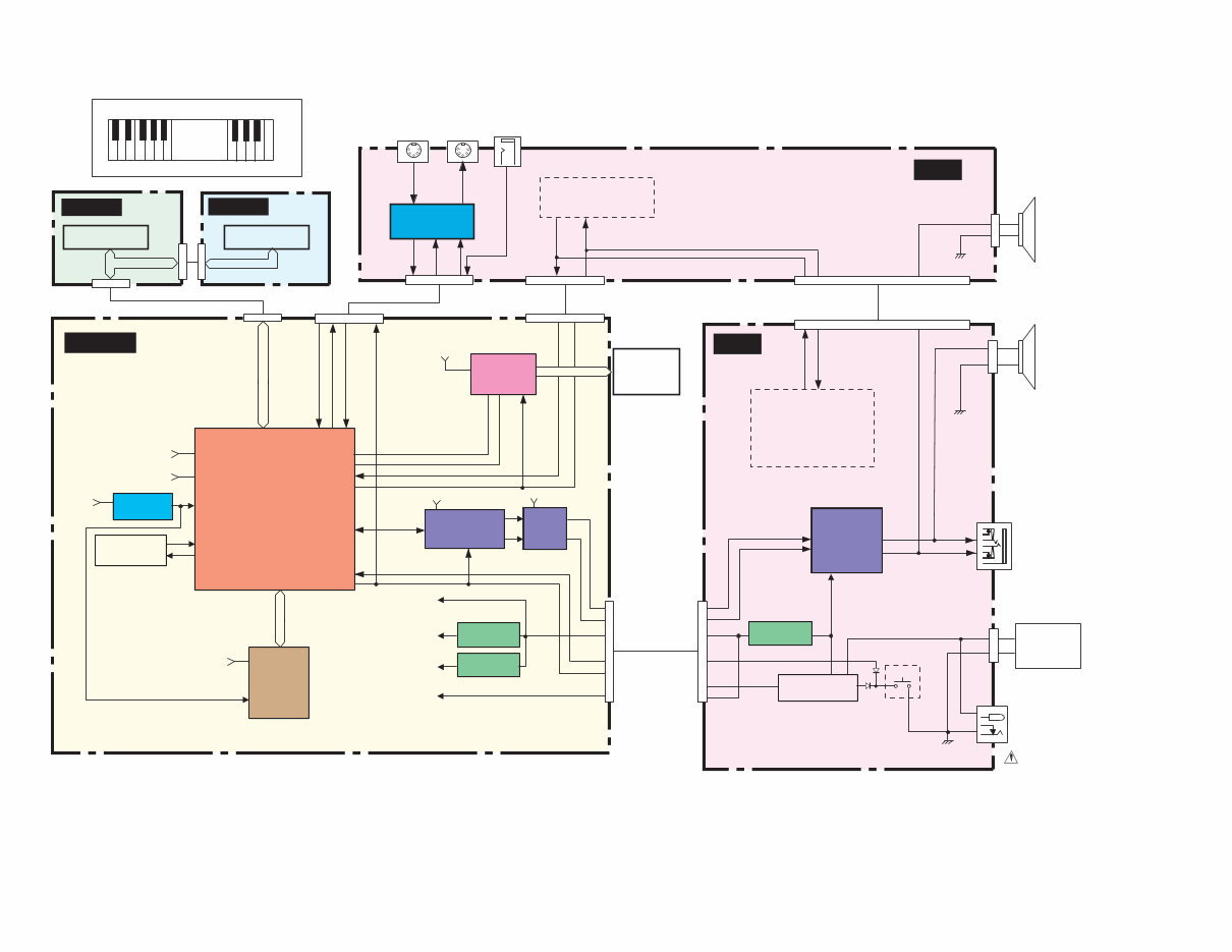
■ BLOCK DIAGRAM (ブロックダイアグラム)
DMLCD
(C1~B3)
(C4~C6)
MK-H
MK-L
Keybord 61KEY
(16N)
NON TOUCH RESPONSE
1
4
2
5
3
1
4
2
5
3
CN202
(2P)
CN303
(10P)
CN104
(10P)
CN201
(2P)
SPEAKER L
4
Ω
12cm
4
Ω
12cm
CN101
(3P)
JK101
JK102
(8P)
CN302 (6P)
SUSTAIN
MIDI
OUT
JK302
JK301
JK303
IN
MIDI I / F
IC301(6P)
TR301,302
KEYBOARD SW
MATRIX
KEYBOARD SW
MATRIX
SW MATRIX
SW05,06,11,12
SW17,18,22-36
CN301 (12P)
2/2
IC301
(80P)
LCD
DRIVER
+5D
OUT1-6
CN603
(6P)
CN602
(12P)
LCD
DISPLAY
1/2
CN601
(10P)
CN103
(10P)
IC101
(3P)
REGULATOR
+5V
REGULATOR
+2.5V
REGULATOR
+3.3V
IC401 (3P)
IC402 (3P)
+2.5V
+5D
+3.3D
+5A
STANDBY
SW
STANDBY/ON
TR101,102
SW101
POWER AMP
BA5417
IC201
(15P)
SW MATRIX
SW01-04,
SW07-10,
SW13-16,19
L
R
OUT1-4
IN1-4
IN1-6
OUT1-6
SPEAKER R
PHONES /
OUTPUT
DC IN 12V
BATTERYS
1.5V x 6
AC adaptor
PA-3B/3C
"AA"SIZE,LR6 or
EQUIVALENT BATTERIES.
SYSCK
BCLK
WCLK
SDO
IN1-6
RS
ENB
+5A
IC201 (16P)
24bit
DAC
AK4385ET
LPF
IC202 (8P)
R
R
+B
L
L
+2.5V
+3.3D
SWL01
YMW767-VT
IC101
(128P)
16.9344MHz
CRYSTAL
RESONATOR
RESET
+3.6V
50ms
IC103
(5P)
X101
12
13
70-76,78-86
91-103,105-108,110-114
25-30,
67,68,87
115,121-123,
125-128
16
4
5
17,24,41,47,
66,90,120
15,46,
89,119
1-4
14
37
12
8
6,5
2,3
5
9.10
7
1
11
12
3
4
5
11,12
34
117
40,42-44
35 39
48-55
38,57-61
32
31
36
MASK
ROM
32M
PROG/WAVE
IC102
(48P)
+3.3D
+5D
MD00-15
MA01-22
+5A
N11-16
B11-16
SCLK
SCLK
PSWI
PSWO
PSWO
PSWI
PSWO
PSWO
CN501
(17P)
XI
XO
RXD0
RXD0
TXD0
TXD0
OUT1-6
+5D
+5A
39-46
38
36
33
28CA1-8834618
–
+
PNAM
PNAM
PSR-E213/YPT-210
9
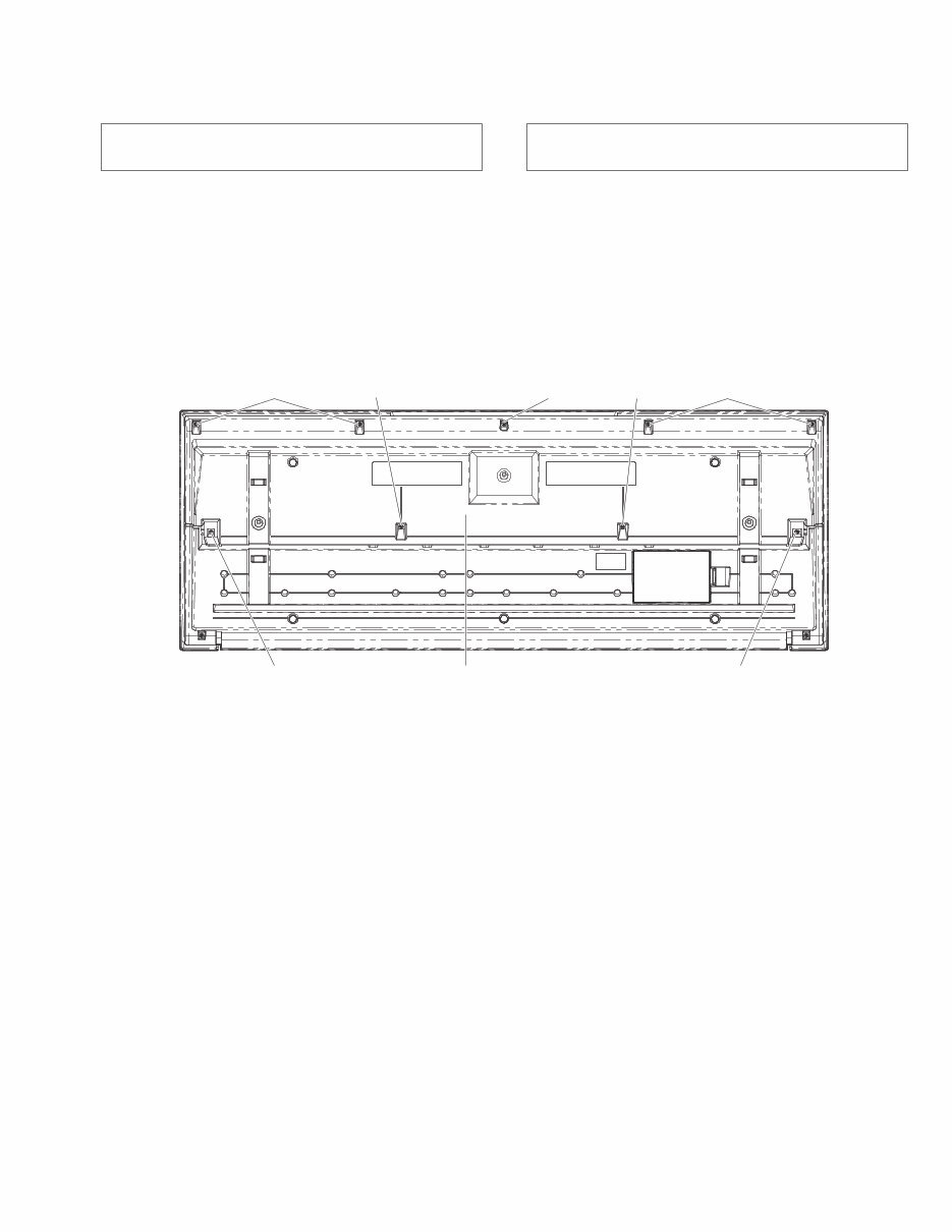
■ DISASSEMBLY PROCEDURES (分解手順)
1. 下ケースAss'y(所要時間:約1分)
1-1 [250A]のネジ5本、[260A]のネジ2本と[300]のネジ2本
を外して、下ケースAss'yを外します。(図 1)
[250A] : Bind Head Tapping Screw-B 3x12 MFZN2W3 (WE987400) Bタイト+BIND
[260A] : Bind Head Screw 3x30 MFZN2W3 (WF491000) Bタイト+BIND
[300] : Bind Head Screw 3x20 MFZN2W3 (WF489300) Bタイト+BIND
Fig. 1 (図 1)
Caution: Be sure to attach the removed filament tape just
as it was before removal.
注意: 分解時に取り外したフィラメントテープは、必ず
元通りに取り付けてください。
1. Lower Case Assembly
(Time required: About 1 minute)
1-1 Remove the five (5) screws marked [250A], two (2)
screws marked [260A], and two (2) screws marked [300].
The lower case assembly can then be removed. (Fig. 1)
• Bottom view (下から見た図)�
Lower Case Assembly
(下ケースAss'y)�
[260A] [250A] [260A] [250A] [250A]
[300] [300]

PSR-E213/YPT-210
10
2. DMLCD Circuit Board, LCD Display
(Time required: About 3 minutes each)
2-1 Remove the lower case assembly. (See procedure 1)
2-2 DMLCD Circuit Board
2-2-1 Remove the eight (8) screws marked [160A]. The
DMLCD circuit board can then be removed. (Fig. 2)
* When attaching or removing the MK wire (DMLCD cir-
cuit board: CN501), insert or pull the MK wire while press-
ing the both side of the connector downward. (Fig. 3)
* When installing the DMLCD circuit board, tighten the
screws 1 through 8 in numerical order. (Fig. 2)
2-3 LCD Display
2-3-1 Remove the DMLCD circuit board. (See procedure 2-2)
2-3-2 Remove the rubber connector and LCD holder A.
The LCD display can then be removed. (Fig. 4)
* When attaching the rubber connector, set the con-
ductive part to face inside. (Fig. 4)
3. PNAM Circuit Board (1/2, 2/2)
(Time required: About 3 minutes each)
3-1 Remove the lower case assembly. (See procedure 1)
3-2 PNAM Circuit Board 1/2
3-2-1 Remove the eleven (11) screws marked [160B]. The
PNAM circuit board 1/2 can then be removed. (Fig. 2)
3-3 PNAM Circuit Board 2/2
3-3-1 Remove the eight (8) screws marked [160C]. The PNAM
circuit board 2/2 can then be removed. (Fig. 2)
* When replacing the PNAM circuit board, remove the
wiring assembly GND1 from the old PNAM circuit board
and then attach it on the new PNAM circuit board if the
wiring assembly GND1 is originally installed. For details,
refer to page 18. (U only)
4. Speaker (Time required: About 2 minutes)
4-1 Remove the lower case assembly. (See procedure 1)
4-2 Remove the four (4) screws marked [30]. The speaker
can then be removed. (Fig. 2)
* The right and left speakers can be removed in the
same manner.
5. Lower Case Keyboard Assembly
(Time required: About 3 minutes)
5-1 Remove the lower case assembly. (See procedure 1)
5-2 Remove the two (2) screws marked [250B] and screw
marked [260B]. The lower case keyboard assembly can
then be removed. (Fig. 2)
* When attaching or removing the MK wire (DMLCD cir-
cuit board: CN501), insert or pull the MK wire while press-
ing the both side of the connector downward. (Fig. 3)
2. DMLCDシート、液晶ディスプレイ
(所要時間:各約3分)
2-1 下ケースAss'yを外します。(1項参照)
2-2 DMLCDシート
2-2-1 [160A]のネジ8本を外して、DMLCDシートを外しま
す。(図 2)
※MK線材(DMLCDシート:CN501)の取り付け、取り
外しは、コネクタの両脇を下に押しながらMK線材
を抜き差しします。(図 3)
※ DMLCDシートを取り付けるときは、1から8の順で
ネジを締めてください。(図 2)
2-3 液晶ディスプレイ
2-3-1 DMLCDシートを外します。(2-2項参照)
2-3-2 ゴムコネクタとLCDホルダーAを外して、液晶ディスプ
レイを外します。(図 4)
※ ゴムコネクタ-を取り付けるときは導電部を内側の
向きにしてください。(図 4)
3. PNAMシート(1/2、2/2)
(所要時間:各約3分)
3-1 下ケースAss'yを外します。(1項参照)
3-2 PNAMシート1/2
3-2-1 [160B]のネジ11本を外して、PNAMシート1/2を外しま
す。(図 2)
3-3 PNAMシート2/2
3-3-1 [160C]のネジ8本を外して、PNAMシート2/2を外しま
す。(図 2)
4. スピーカ(所要時間:約2分)
4-1 下ケースAss'yを外します。(1項参照)
4-2 [30]のネジ4本を外して、スピーカーを外します。(図 2)
※ 左右のスピーカは同じように外せます。
5. 下ケース鍵盤Ass'y(所要時間:約3分)
5-1 下ケースAss'y を外します。(1項参照)
5-2 [250B]のネジ2本と、[260B]のネジ1本を外して、下
ケース鍵盤Ass'yを外します。(図 2)
※MK線材(DMLCDシート:CN501)の取り付け、取り
外しは、コネクタの両脇を下に押しながらMK線材
を抜き差しします。(図 3)
You're Reading a Preview
What's Included?
 Lifetime Access
Fast Download Speeds
Online & Offline Access
Access PDF Contents & Bookmarks
Full Search Facility
Print one or all pages of your manual
$31.99
YAMAHA PSR-E213/YPT-210 Service Manual
Viewed 91 Times Today

What's Included?
Lifetime Access
Fast Download Speeds
Online & Offline Access
Access PDF Contents & Bookmarks
Full Search Facility
Print one or all pages of your manual
$31.99

Secure transaction
What's Included?
Lifetime Access
Fast Download Speeds
Online & Offline Access
Access PDF Contents & Bookmarks
Full Search Facility
Print one or all pages of your manual
Description
The YAMAHA PSR-E213/YPT-210 Service Manual is a comprehensive guide that provides essential technical information for the repair and maintenance of the YAMAHA PSR-E213 and YPT-210 electronic keyboards. This manual is invaluable for both professional mechanics and DIY enthusiasts.
- Specifications
- Panel Layout
- Circuit Board Layout & Wiring
- Block Diagram
- Disassembly Procedures
- LSI Pin Description
- IC Block Diagram
- Circuit Boards
- Test Program
- Midi Implementation Chart
- Midi Data Format
- Parts List
- Overall Circuit Diagram
This manual is available in English and consists of 37 pages. It is compatible with both Windows and MAC platforms.


