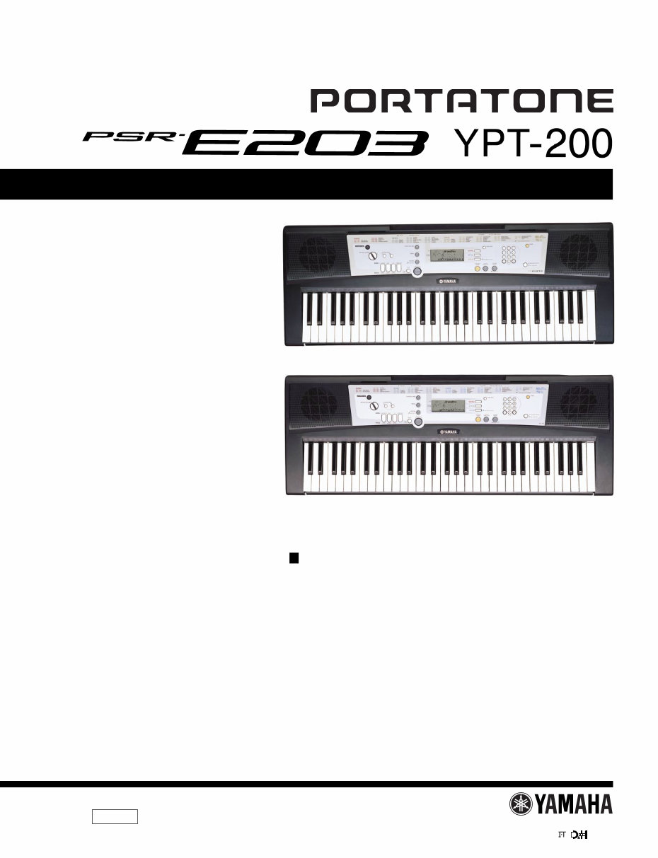
Yamaha psr-e203 psre203 ypt-200 ypt200 service manual full
Have a question?Ask Us
What's Included?
Fast Download Speeds
Online & Offline Access
Access PDF Contents & Bookmarks
Full Search Facility
Print one or all pages of your manual
Copyright (c) Yamaha Corporation. All rights reserved. PDF-K147 ’05.05
SERVICE MANUAL
HAMAMATSU, JAPAN
CONTENTS
SPECIFICATIONS ................................................................. 3
PANEL LAYOUT .................................................................. 4
CIRCUIT BOARD LAYOUT & WIRING ................................ 5
BLOCK DIAGRAM ................................................................ 6
DISASSEMBLY PROCEDURE ............................................. 7
LSI PIN DESCRIPTION ....................................................... 11
IC BLOCK DIAGRAM ......................................................... 12
CIRCUIT BOARDS .............................................................. 13
TEST PROGRAM ............................................................... 16
MIDI IMPLEMENTATION CHART ..................................... 18
MIDI DATA FORMAT ......................................................... 19
PARTS LIST
OVERALL CIRCUIT DIAGRAM
PK 001733
/
PSR-E203
YPT-200
2
PSR-E203/YPT-200
WARNING: CHEMICAL CONTENT NOTICE!
The solder used in the production of this product contains LEAD. In addition, other electrical/electronic and/or plastic (Where
applicable) components may also contain traces of chemicals found by the California Health and Welfare Agency (and possibly
other entities) to cause cancer and/or birth defects or other reproductive harm.
DO NOT PLACE SOLDER, ELECTRICAL/ELECTRONIC OR PLASTIC COMPONENTS IN YOUR MOUTH FOR ANY REASON WHAT
SO EVER!
Avoid prolonged, unprotected contact between solder and your skin! When soldering, do not inhale solder fumes or expose
eyes to solder/flux vapor!
If you come in contact with solder or components located inside the enclosure of this product, wash your hands before handling
food.
IMPORTANT NOTICE
This manual has been provided for the use of authorized Yamaha Retailers and their service personnel. It has been assumed
that basic service procedures inherent to the industry, and more specifically Yamaha Products, are already known and under-
stood by the users, and have therefore not been restated.
WARNING : Failure to follow appropriate service and safety procedures when servicing this product may result in per-
sonal injury, destruction of expensive components and failure of the product to perform as specified. For
these reasons, we advise all Yamaha product owners that all service required should be performed by an
authorized Yamaha Retailer or the appointed service representative.
IMPORTANT : This presentation or sale of this manual to any individual or firm does not constitute authorization certifi-
cation, recognition of any applicable technical capabilities, or establish a principal-agent relationship of
any form.
The data provided is belived to be accurate and applicable to the unit(s) indicated on the cover. The research engineering, and
service departments of Yamaha are continually striving to improve Yamaha products. Modifications are, therefore, inevitable
and changes in specification are subject to change without notice or obligation to retrofit. Should any discrepancy appear to
exist, please contact the distributor’s Service Division.
WARNING : Static discharges can destroy expensive components. Discharge any static electricity your body may have
accumulated by grounding yourself to the ground bus in the unit (heavy gauge black wires connect to
this bus.)
IMPORTANT : Turn the unit OFF during disassembly and parts replacement. Recheck all work before you apply power
to the unit.
Components having special characteristics are marked and must be replaced with parts having specification equal to those
originally installed.
WARNING

PSR-E203/YPT-200
3
SPECIFICATIONS
Keyboards
• 61 standard-size keys (C1-C6)
Display
• LCD display
Setup
• STANDBY/ON
• MASTER VOLUME: [+], [-] buttons
Panel Controls
• [L], [R], [LISTEN & LEARN], [TIMING], [WAITING], [A-B
REPEAT]/[ACMP ON/OFF], [REW]/[INTRO/ENDING/rit.],
[FF]/[[MAIN/AUTO FILL], [TEMPO/TAP],
[PAUSE]/[SYNC START], [START/STOP], [SONG], [STYLE],
[VOICE], [FUNCTION], [PORTABLE GRAND], [SOUND
EFFECT KIT], [REVERB ON/OFF], [DEMO],
[METRONOME ON/OFF], number buttons [0]-[9], [+], [-]
Voice
• 129 panel voices + 4drum kits + 1 sound effect kit
• Polyphony: 32
Style
• 100 preset Styles
• Style Control:
ACMP ON/OFF, SYNC START, START/STOP,
INTRO/ENDING/rit., MAIN/AUTO FILL
• Fingering: Multi fingering
• Style Volume
Education Feature
• Chord Dictionary
• Lesson 1-3
Function
• Style Volume, Song Volume, Tuning, Transpose, Split Point,
Main voice (Volume, Octave), Reverb Type, Reverb level,
Panel Sustain, Local On/Off, External Clock, Initial Setup Send,
Time Signature, Metronome Volume, Demo Cancel
Effects
• Reverb: 9 types
Song
• 102 Preset Songs
• Song Volume
MIDI
• Local On/Off
• Initial Setup Send
• External Clock
Auxiliary jacks
• PHONES/OUTPUT, DC IN 12V, MIDI in/out, SUSTAIN
Amplifier
• 2.5W + 2.5W
Speakers
• 12cm x 2
Power Consumption
• 10W (When using PA-3C power adaptor)
Power Supply
• Adaptor:Yamaha PA-3B/3C AC power adaptor
• Batteries:Six “AA” size, LR6 or equivalent batteries
Dimensions (W x D x H)
• 945 x 348 x 110 mm
(37-1/4" x 13-2/3" x 4-1/3")
Weight
• 4.4kg (9 lbs. 11 oz.) (not including batteries)
Supplied Accessories
• Music Rest
• Owner’s Manual
Optional Accessories
• AC Power Adaptor: PA-3B/PA-3C
• USB-MIDI Interface: UX16
• Footswitch: FC4/FC5
• Keyboard Stand: L-2C/L-2L
• Headphones: HPE-150/HPE-30
4
PSR-E203/YPT-200
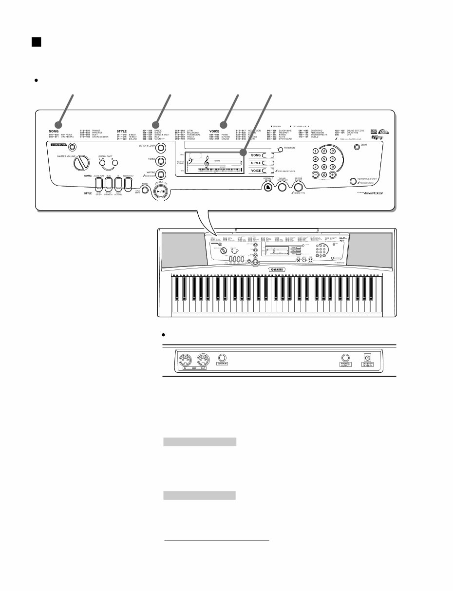
PANEL LAYOUT
GrandPno 001
001
w
q
e
!4 !5 !7 !6
Song List
Front Panel
Rear Panel
@6 @5 @4 @3
GrandPno 001
001
r
t
!8 !9
y
!3
!2
!1
u
!0
o
i
@2 @1 @0
Voice List Display Style List
Front Panel
q [STANDBY/ON] switch
w MASTER VOLUME
[+] button
[–] button
e LESSON PART
[L] button
[R] button
r [LISTEN & LEARN] button
t [TIMING] button
y [WAITING] button
u [FUNCTION] button
i [SONG] button
o [STYLE] button
!0 [VOICE] button
!1 Number buttons [0]-[9], [+], [–]
!2 [DEMO] button
!3 [METRONOME ON/OFF] button
When the Song mode
!4 [A-B REPEAT] button
!5 [REW] button
!6 [FF] button
!8 [PAUSE] button
When the Style mode
!4 [ACMP ON/OFF] button
!5 [INTRO/ENDING/rit.] button
!6 [MAIN/AUTO FILL] button
!8 [SYNC START] button
!7 [TEMPO/TAP] button
!9 [START/STOP] button
@0 [PORTABLE GRAND] button
@1 [SOUND EFFECT KIT] button
@2 [REVERB ON/OFF] button
Rear Panel
@3 MIDI IN/OUT terminals
@4 SUSTAIN jack
@5 PHONES/OUTPUT jack
@6 DC IN 12V jack
PSR-E203/YPT-200
5
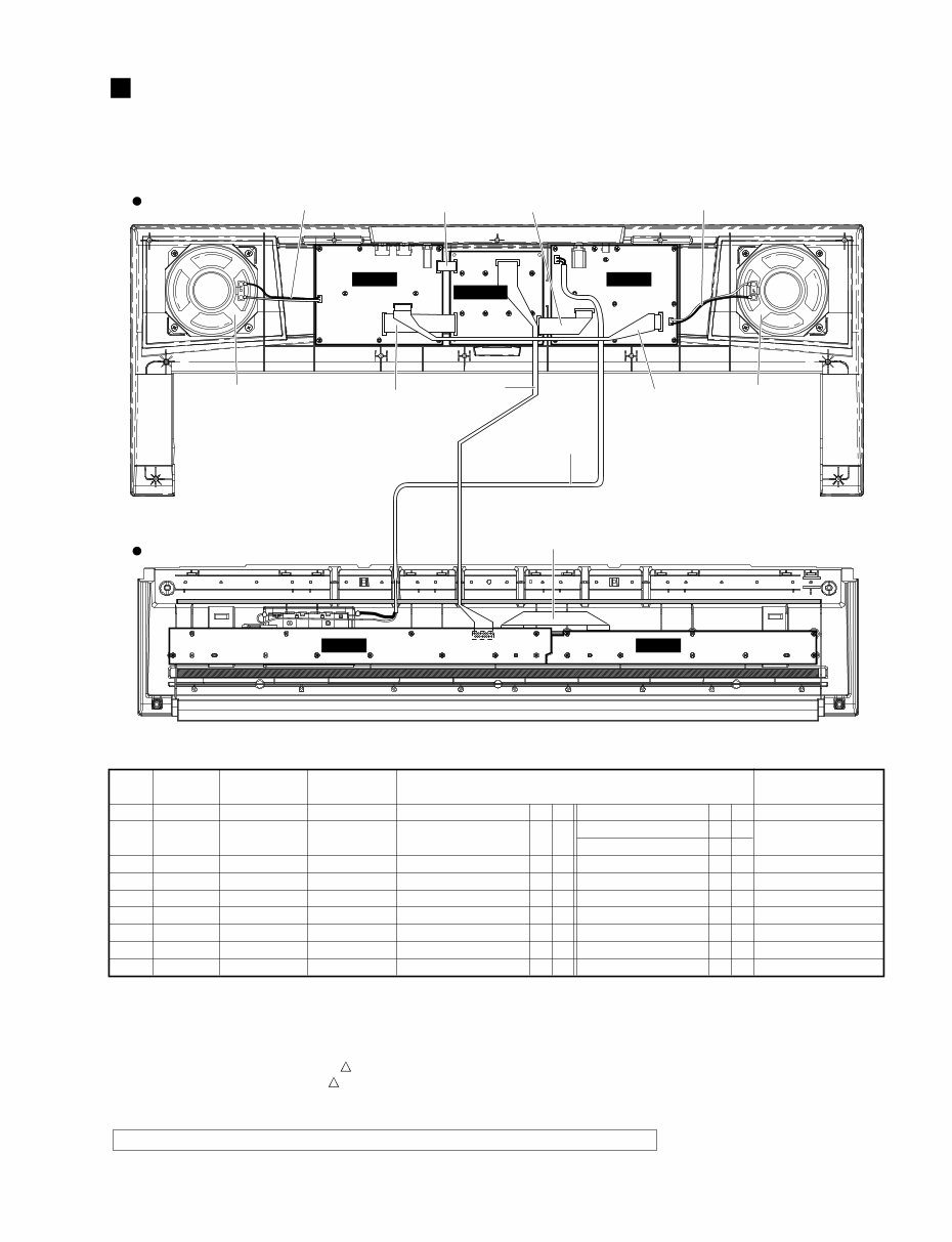
CIRCUIT BOARD LAYOUT & WIRING
Upper case side
Lower case side
PNAM
MK-L MK-H
2/2
PNAM
DMLCD 1/2
Speaker L Speaker R
i
u r
e
q
w
o
y t
Location
30
120
WH103
WH104
WH201
WH202
WH301
WH302
120c
*1
*1
*3
*3
*3
*3
*3
*3
*1
*4
*5
*4
*4
*5
*5
*4
*4
*4
*1
*2
*2
*1
*3
*2
*2
*1
*1
*1
*4
*7
*7
*4
*4
*6
*6
*4
*4
*4
q
w
e
r
t
y
u
i
o
MK
BATTERY
PN3
PN
SP
SP
PN4
PN1
MK
MK-L
PNAM1/2-CN101
PNAM1/2-CN103
PNAM1/2-CN104
PNAM1/2-CN201
PNAM2/2-CN202
PNAM2/2-CN301
PNAM2/2-CN302
MK-L
DMLCD-CN501
Battery terminal A
Battery terminal B
DMLCD-CN601
PNAM2/2-CN303
Speaker-L
Speaker-R
DMLCD-CN602
DMLCD-CN603
MK-H
17P
3P
10P
10P
2P
2P
12P
6P
11P
WE156400
(WE15510)
(WE15580)
(WE15550)
(WE67670)
(WE67670)
(WE15600)
(WE15560)
(V719030)
Parts No. Destination Remarks
Connector
Assembly
No.
*The parts with “( )” in “Part No.” are not available as spare parts.
*1: Installation
*2: Manual soldering
*3: Dip soldering
*4: Edge mark is adjusted to Pin 1 mark ( mark).
*5: Red wire is adjusted to Pin 1 mark ( mark).
*6: Speaker (Red wire is connected to + terminal.)
*7: Battery terminal A (Black wire), Battery terminal B (Red wire)
Caution: Be sure to attach the removed filament tape just as it was before removal.
+ +
– – + +
– –
6
PSR-E203/YPT-200
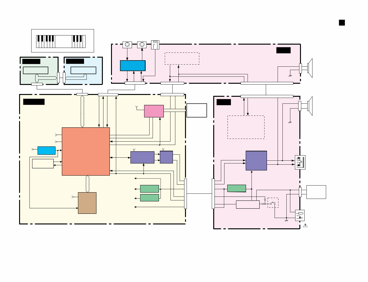
BLOCK DIAGRAM
DMLCD
Keybord 61KEY
(16N)
NON TOUCH RESPONSE
1
4
2
5
3
1
4
2
5
3
(C1~B3)
(C4~C6)
CN202
(2P)
CN303
(10P)
CN104
(10P)
CN201
(2P)
SPEAKER L
4Ω 12cm
CN101
(3P)
JK101
JK102
(8P)
CN302 (6P)
SUSTAIN MIDI
OUT
JK302
JK301
JK303
IN
MIDI I / F
IC301(6P)
TR301,302 KEYBOARD SW
MATRIX
KEYBOARD SW
MATRIX
SW MATRIX
SW05,06,11,12
SW17,18,22-36
CN301 (12P)
PNAM 2/2
IC301
(80P)
LCD
DRIVER
+5D
OUT1-6
CN603
(6P)
CN602
(12P)
LCD
DISPLAY
PNAM 1/2
CN601
(10P)
CN103
(10P)
IC101
(3P)
REGULATOR
+5V
REGULATOR
+2.5V
REGULATOR
+3.3V
IC401 (3P)
IC402 (3P)
+2.5V
+5D
+3.3D
+5A
STANDBY
SW
STANDBY/ON
TR101,102
SW101
POWER AMP
BA5417
IC201
(15P)
SW MATRIX
SW01-04,
SW07-10,
SW13-16,19
L
R
OUT1-4
IN1-4
IN1-6
OUT1-6
SPEAKER R
4Ω 12cm
PHONES /
OUTPUT
DC IN 12V
BATTERYS
1.5V x 6
AC adaptor
PA-3B/3C
"AA"SIZE,LR6 or
EQUIVALENT BATTERIES.
SYSCK
BCLK
WCLK
SDO
IN1-6
RS
ENB
+5A
IC201 (16P)
24bit
DAC
AK4385ET
LPF
IC202 (8P)
R
R
+B
L
L
+2.5V
+3.3D
SWL01
YMW767-VT
IC101
(128P)
16.9344MHz
CRYSTAL
RESONATOR
RESET
+3.6V 50ms
IC103
(5P)
X101
12
13
70-76,78-86
91-103,105-108,110-114
25-30,
67,68,87
115,121-123,
125-128
16
4
5
17,24,41,47,
66,90,120
15,46,
89,119
1-4
14
37
12
8
6,5
2,3
5
9.10
7
1
11
12
3
4
5
11,12
34
117
40,42-44
35 39
48-55
38,57-61
32
31
36
MASK
ROM
32M
PROG/WAVE
IC102
(48P)
+3.3D
+5D
MD00-15
MA01-22
+5A
MK-H
MK-L
N11-16
B11-16
SCLK
SCLK
PSWI
PSWO
PSWO
PSWI
PSWO
PSWO
CN501
(17P)
XI
XO
RXD0
RXD0
TXD0
TXD0
OUT1-6
+5D
+5A
39-46 38 36
33
28CA1-8834618
–
+
PSR-E203/YPT-200
7
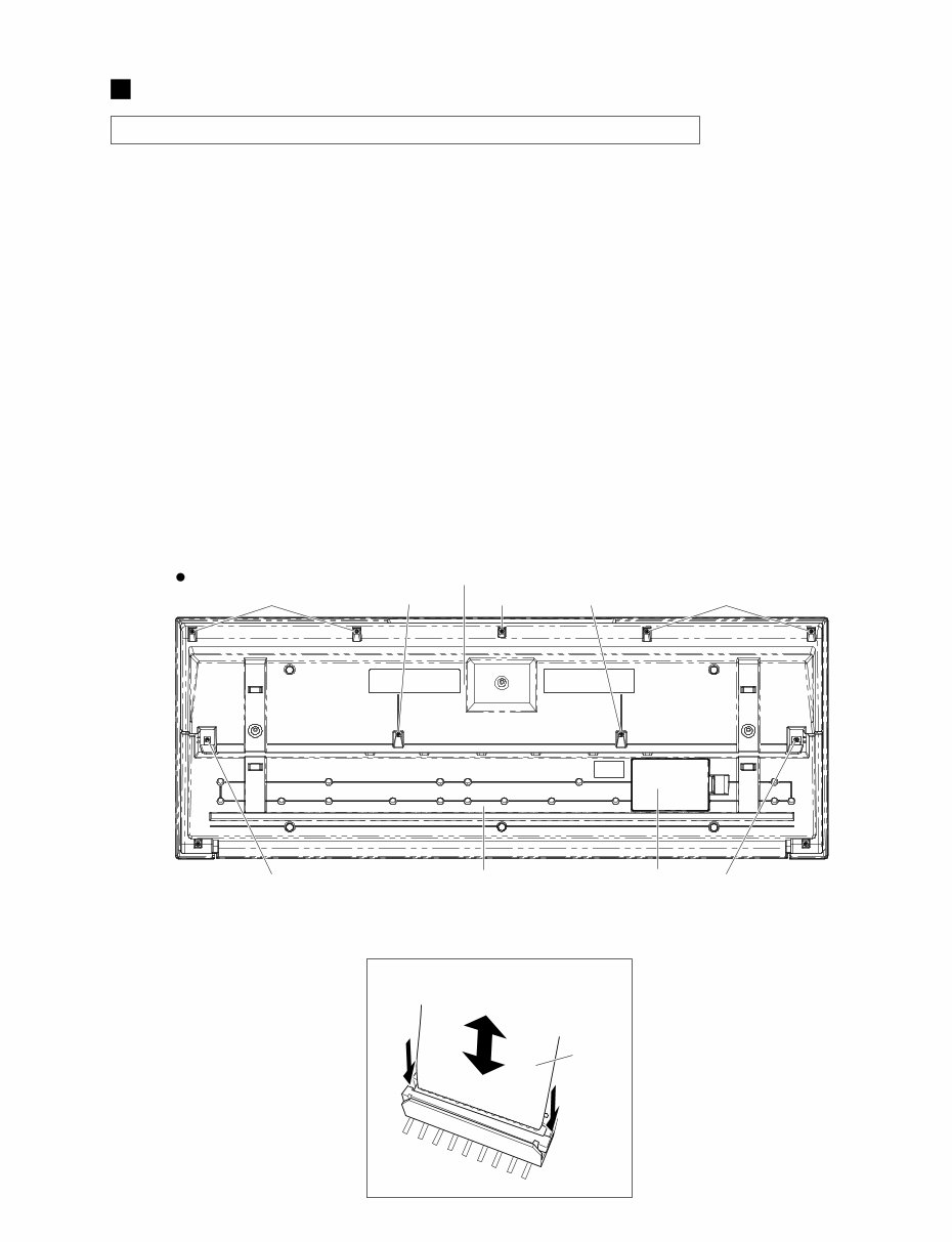
DISASSEMBLY PROCEDURE
1. Lower Case Assembly
(Time required: About 1 minute)
1-1 Remove the five (5) screws marked [250A], two (2)
screws marked [260A], and two (2) screws marked
[300]. The lower case assembly can then be
removed. (Fig. 1)
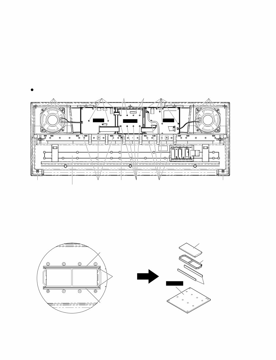
2. DMLCD Circuit Board, LCD Display
(Time required: About 3 minutes each)
2-1 Remove the lower case assembly. (See procedure 1)
2-2 DMLCD Circuit Board
2-2-1 Remove the eight (8) screws marked [160A]. The
DMLCD circuit board can then be removed. (Fig. 3)
* When attaching the Mk wire (DMLCD circuit board:
CN501), insert or pull the Mk wire while pressing
the both side portions of the connector downward.
(Fig. 2)
* When installing the DMLCD circuit board, tighten
the screws 1 through 8 in numerical order. (Fig. 3)
(Fig.1)
Caution: Be sure to attach the removed filament tape just as it was before removal.
[250]: Bind Head Tapping Screw-B 3.0X12 MFZN2Y (VE683000)
[260]: Bind Head Tapping Screw-B 3.0X30 MFZN2Y (V7213700)
[300]: Bind Head Tapping Screw-B 3.0X20 MFZN2Y (VI064600)
2-3 LCD Display
2-3-1 Remove the DMLCD circuit board.
(See procedure 2-2)
2-3-2 Remove the rubber connector and LCD holder A.
The LCD display can then be removed. (Fig. 4)
* When attaching the rubber connector, set the
conductive part to face inside. (Fig. 4)
3. PNAM Circuit Board (1/2, 2/2)
(Time required: About 3 minutes each)
3-1 Remove the lower case assembly.
(See procedure 1)
3-2 PNAM Circuit Board 1/2
3-2-1 Remove the eleven (11) screws marked [160B]. The
PNAM circuit board 1/2 can then be removed. (Fig. 3)
3-3 PNAM Circuit Board 2/2
3-3-1 Remove the eight (8) screws marked [160C]. The
PNAM circuit board 2/2 can then be removed. (Fig. 3)
[260A] [250A] [260A]
Battery Lid Assembly Lower Case Keyboard Assembly
[250A] [250A]
[300] [300]
Lower Case Assembly Bottom view
Attaching and Removing the Mk Wire
DMLCD Circuit Board: CN501
MK Wire
(Fig.2)
8
PSR-E203/YPT-200
4. Speaker (Time required: About 2 minutes)
4-1 Remove the lower case assembly. (See procedure 1)
4-2 Remove the four (4) screws marked [30]. The
speaker can then be removed. (Fig. 3)
* The right and left speakers can be removed in the
same way.
[30]: Bind Head Tapping Screw-B 4.0X8 MFZN2Y (EP640410)
[160]: Bind Head Tapping Screw-B 3.0X8 MFZN2Y (EP600250)
[250]: Bind Head Tapping Screw-B 3.0X12 MFZN2Y (VE683000)
[260]: Bind Head Tapping Screw-B 3.0X30 MFZN2Y (V7213700)
(Fig.3)
[160C]
[160A] [260B] [160B] [160C]
[160B] [30] [30]
DMLCD
PNAM
2/2
PNAM
1/2
[250B] [250B]
Bottom view
Lower Case Keyboard Assembly
[160A] [160A]
CN501
3
1
4
7
5
8
6
2
LCD
Conductor side
Rubber Connector
Rubber Connector
Rubber Connector
LCD Holder A
DMLCD
(Fig.4)
PSR-E203/YPT-200
9
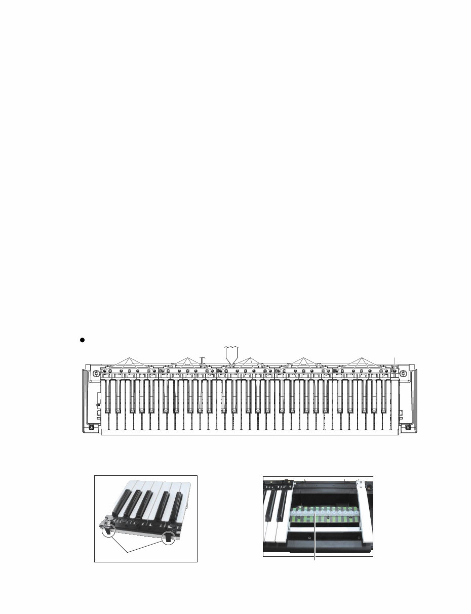
5. Lower Case Keyboard Assembly
(Time required: About 3 minutes)
5-1 Remove the lower case assembly. (See procedure 1)
5-2 Remove the two (2) screws marked [250B] and
screw marked [260B]. The lower case keyboard
assembly can then be removed. (Fig. 3)
* When attaching the Mk wire (DMLCD circuit board:
CN501), insert or pull the Mk wire while pressing
the both side portions of the connector downward.
(Fig. 2)
6. Keyboard Assembly
6-1 Remove the lower case keyboard assembly.
(See procedure 5)
6-2 White and black keys for one octave unit are
combined as a set. There are five sets in total.
Remove the four (4) screws marked [110A]. The
keyboard can then be removed. (Fig. 5) There are
two (2) hooks at the back of the black keys. (Photo.1)
Press the hook for the black key and lift a little, and
pull forward to remove the hook for the black key to
lift it.
6-3 To remove the white key C6, remove the screw
marked [110B], press the hook at the back to lift a
little, and pull it forward to remove the hook to lift it.
7. Rubber Contact
7-1 Remove the lower case keyboard assembly.
(See procedure 5)
7-2 Remove the keyboard corresponding to the rubber
contacts to be removed. (See procedure 6)
7-3 Remove the rubber contacts. (Photo. 2)
8. MK-L Circuit Board, MK-H Circuit Board
(Time required: About 6 minutes each)
8-1 Remove the lower case keyboard assembly.
(See procedure 5)
8-2 MK-L Circuit Board
8-2-1 Remove the keyboards from C1 to B3.
(See procedure 6)
8-2-2 Remove the four (4) screws marked [90A], and eight
(8) screws marked [100A]. The MK-L circuit board
can then be removed. (Fig. 6)
8-3 MK-H Circuit Board
8-3-1 Remove the keyboards from C4 to C6.
(See procedure 6)
8-3-2 Remove the three (3) screws marked [90B], and five
(5) screws marked [100B]. The MK-H circuit board
can then be removed. (Fig. 6)
[110]: Bind Head Tapping Screw-B 3.0X20 MFZN2Y (EP600680)
(Fig.5)
(Photo.1)
(Photo.2)
<Lower case keyboard assembly>
[110A]
C1 B2 B3 C4 C6
[110A] [110A] [110A] [110B] [110A]
Top view
Hook
Rubber Contact
10
PSR-E203/YPT-200
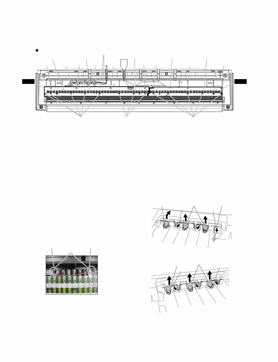
9. How to Remove Spring Terminals.
A Spring Terminal A, Spring Terminal B
9-1 Remove the lower case keyboard assembly.
(See procedure 5)
9-2 Remove the keyboards from C1 to B2.
(See procedure 6)
9-3 Remove the battery connector assembly soldered
to the spring terminal A and spring terminal B.
(Fig. 6, Photo. 3)
9-4 Reverse the lower case keyboard assembly and
remove the battery lid assembly. (Fig. 1)
9-5 Lift the spring terminal A a little and slide it rightward
to remove it. (Fig. 7)
9-6 Remove the hook for the spring terminal B to pull it
out from inside. (Fig. 7)
[90]: Bind Head Tapping Screw-B 3.0X8 MFZN2Y (EP600250)
[100]: Bind Head Tapping Screw-P SP 3.0X12 MFZNBL (VZ313100)
(Fig.6)
(Fig.7)
(Fig.8)
(Photo.3)
[90A]
[100A]
[90A] [90A] [90A] [90B] [90B] [90B]
Rubber Contact Rubber Contact Rubber Contact
Rubber Contact
Battery Connector Assembly
Rubber Contact
Soldering Soldering
[100A] [100B]
MK-L MK-H
Top view
Soldering
Spring Terminal A Spring Terminal B
Battery Connector Assembly
Spring Terminal A Spring Terminal D Spring Terminal B
Hook
Hook
Spring Terminal C
Spring Terminal C
Hook
Hook
B Spring Terminal C, Spring Terminal D
9-1 Remove the battery lid assembly at the bottom side
of the lower case keyboard assembly. (Fig. 1)
9-2 Remove the hooks to pull out the spring terminal C
and spring terminal D. (Fig. 7, 8)
You're Reading a Preview
What's Included?
Fast Download Speeds
Online & Offline Access
Access PDF Contents & Bookmarks
Full Search Facility
Print one or all pages of your manual
$33.99
Viewed 56 Times Today


Secure transaction
What's Included?
Fast Download Speeds
Online & Offline Access
Access PDF Contents & Bookmarks
Full Search Facility
Print one or all pages of your manual
$33.99
This comprehensive service manual includes specifications, panel layout, circuit board layout, block diagram, disassembly procedure, LSI pin description, IC block diagram, circuit boards, inspection, MIDI implementation chart, overall circuit diagram, and parts list. It provides detailed instructions and images for repairing and servicing Yamaha products. The manual is an official high-resolution document, ensuring excellent print quality. Instant access is available upon payment, with no shipping delays. The manual is in English and is compatible with various platforms such as Windows, MAC, and Linux. For other Yamaha product service manuals, feel free to inquire.