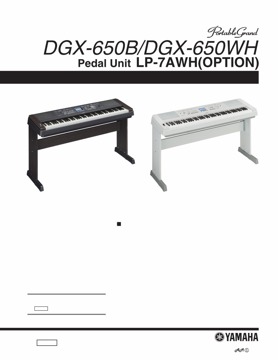
Yamaha dgx650 dgx-650 dgx 650 complete service manual
What's Included?
Lifetime Access
Fast Download Speeds
Online & Offline Access
Access PDF Contents & Bookmarks
Full Search Facility
Print one or all pages of your manual
SERVICE MANUAL HAMAMATSU, JAPAN Copyright (c) Yamaha Corporation. All rights reserved. ’13.06 CL 001889 CONTENTS SPECIFICATIONS ..................................................................... 3 PANEL LAYOUT ....................................................................... 4 CIRCUIT BOARD LAYOUT& WIRING ...................................... 6 BLOCK DIAGRAM.................................................................... 8 DISASSEMBLY PROCEDURE ................................................ 9 LSI PIN DESCRIPTION .......................................................... 20 CIRCUIT BOARDS .................................................................. 24 DM Circuit Board Test Method................................................. 33 TEST PROGRAM .................................................................... 34 BACKUP .................................................................................. 39 INITIALIZATION ...................................................................... 39 SYSTEM BOOTING FLOW CHART ....................................... 40 PARTS LIST (DGX-650B/DGX-650WH) PARTS LIST (LP-7A/LP-7AWH) OVERALL CIRCUIT DIAGRAM As for an optional LP-7A/LP-7AWH pedal unit, refer to the LP-7A/LP-5A service manual (CL 001812 ). DGX-650WH DGX-650B
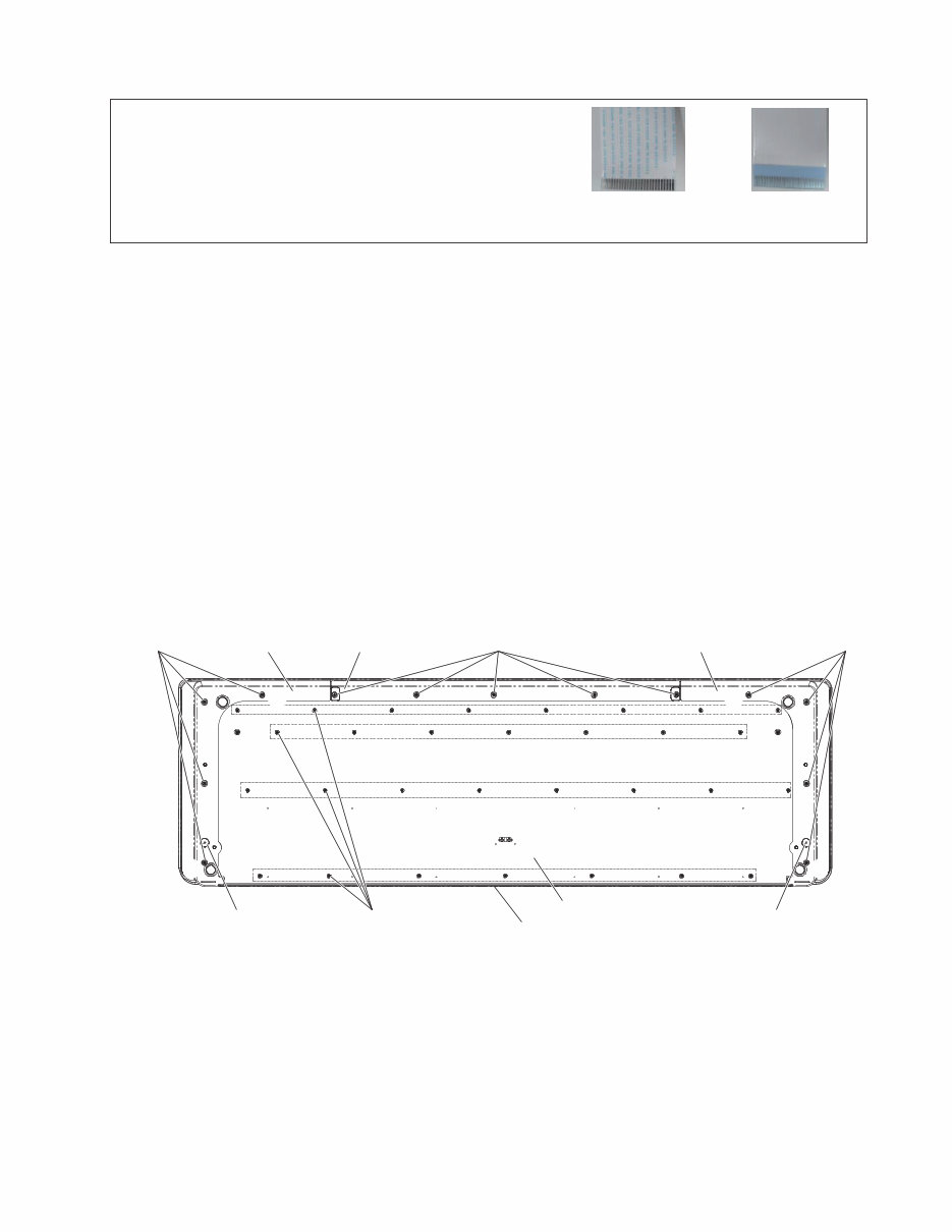
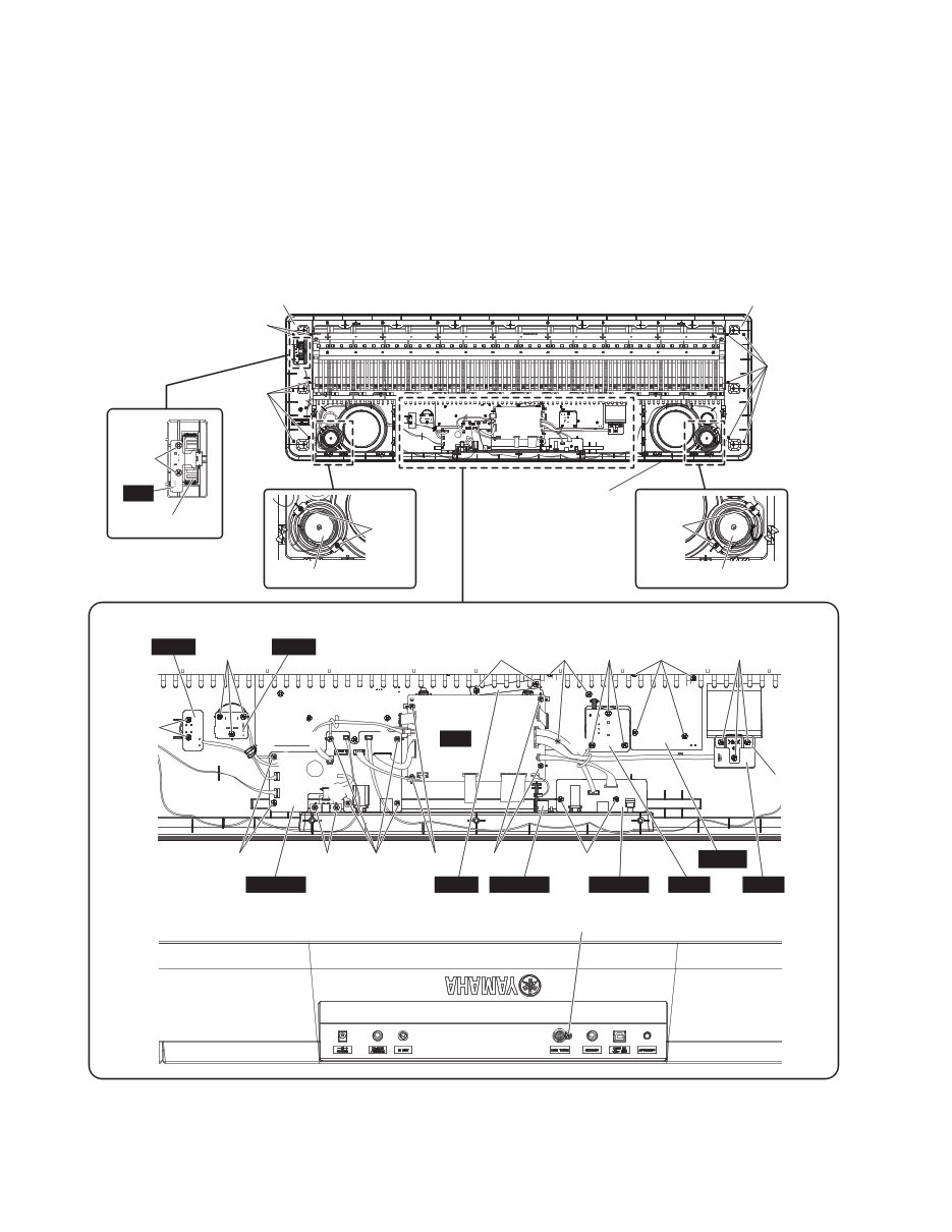
9 DGX-650B/DGX-650WH ■ DISASSEMBLY PROCEDURE 1. Bottom Board Assembly (Time required: About 8 minutes) 1-1 Remove the five (5) screws marked [940A]. The lower case F can then be removed. (Fig.1) 1-2 Remove the four (4) screws marked [940B] and the guide screw marked [950A]. The lower case L can then be removed. (Fig.1) 1-3 Remove the four (4) screws marked [940C] and the guide screw marked [950B]. The lower case R can then be removed. (Fig.1) 1-4 Remove the thirty (30) screws marked [940D]. The bottom board assembly can then be separated from the upper case assembly. (Fig.1) CAUTION: 1) Flat cable’s contacts are visible from the back. Pay attention not to insert and install the cable to the connector inversely. 2) Be surto attach the removed filament tape just as it was before removal. >$@ %RWWRP YLHZ ! 7KH RUGHU RI WKH VFUHZ WLJKWHQLQJ Lower Case F Lower Case L Lower Case R >$@ %RWWRP %RDUG $VVHPEO\ 8SSHU &DVH $VVHPEO\ >'@ [ >%@ >%@ >&@ )URQW 6LGH 3ULQWHG 6LGH %DFN VLGH * When the lower case L is assembled, tighten the screws marked [940B] in the order of 1, 2, 3 and 4. (Fig.1) * When the lower case R is assembled, tighten the screws marked [940C] in the order of 1, 2, 3 and 4. (Fig.1) Fig.1
10 DGX-650B/DGX-650WH Fig.2 2. Circuit Boards and Assemblies (Upper Case Part) (Time required: About 9 minutes) 2-1 Separate the upper case assembly from the bottom board assembly. (See procedure 1.) 2-2 After removing the upper case assembly, remove the following screws. Each circuit board and assembly can then be removed. (Fig.2)(Table 1) > Dqvvqo xkgy @ > Dqvvqo xkgy @ > Tgct xkgy @ 3/4 < Vjg qtfgt qh vjg uetgy vkijvgpkpi Wrrgt Ecug Cuugodn{ ]82C_ ]82C_ ];22N_ ];22M_ ];22K_ ];22E_ ];22F_ ];22C_ ];22C_ ];22D_ ];22D_ ];32C_ ];22L_ ]82D_ Mg{ Dnqem T Mg{ Dnqem N Urgcmgt *Vyggvgt+ *N+ ];22O_ Urgcmgt *Vyggvgt+ *T+ Yjggn Cuugodn{ RD RYT OXT RPT FO CLCEM RGFCN OMQ FLCEM WUD GPE ];22G_ Dtcemgv ];22I_ ];22H_ ];22H_ ];22J_ 3 3 4 4 3 3 3 4 4 4 C C C D 3 4 3 4 3 4
This comprehensive service manual provides detailed specifications, parts list, exploded views, circuit board diagrams, and more for Yamaha products. It is an invaluable resource for both professional mechanics and DIY enthusiasts.
With topics including specifications, panel layout, circuit board layout, block diagram, disassembly procedure, LSI pin description, IC block diagram, circuit boards, inspection, MIDI implementation chart, overall circuit diagram, and parts list, this manual offers step-by-step instructions for repairing and servicing Yamaha devices.
Rest assured, this is the official service and repair manual available in PDF format, ensuring high-resolution quality for printing. Instant access after payment eliminates shipping fees and waiting time, allowing you to commence repairs promptly.
Language: English
Format: PDF
Platform: Windows, MAC, Linux, etc.
For any inquiries about other Yamaha product service manuals, feel free to reach out. Thank you for choosing this manual!
Recently Viewed
5,521,897Happy Clients
2,594,462eManuals
1,120,453Trusted Sellers
15Years in Business
Price:
Actual Price:
Yamaha dgx650 dgx-650 dgx 650 complete service manual