Yamaha DTXPLORER Drum Trigger Module Service Manual & Repair Guide
What's Included?
Lifetime Access
Fast Download Speeds
Online & Offline Access
Access PDF Contents & Bookmarks
Full Search Facility
Print one or all pages of your manual
SERVICE MANUAL ED 011764 Copyright (c) Yamaha Corporation. All rights reserved. PDF-K265 I M Printed in Japan '05.01 ■ CONTENTS SPECIFICATION ....................................................................... 3 PANEL LAYOUT ........................................................................ 4 CONNECTING THE PADS ........................................................ 5 UNIT LAYOUT and WIRING ...................................................... 6 BLOCK DIAGRAM .................................................................... 7 DISASSEMBLY PROCEDURE ................................................. 8 LSI PIN DESCRIPTION .......................................................... 10 IC BLOCK DIAGRAM .............................................................. 12 CIRCUIT BOARDS ................................................................. 13 TEST PROGRAM ................................................................... 18 ERROR MESSAGES .............................................................. 25 MIDI IMPLEMENTATION CHART ........................................... 26 OVERALL CIRCUIT DIAGRAM PARTS LIST DRUM TRIGGER MODULE
DTXPLORER 2 IMPORTANT NOTICE This manual has been provided for the use of authorized Yamaha Retailers and their service personnel. It has been assumed that basic service procedures inherent to the industry, and more specifically Yamaha Products, are already known and understood by the users, and have therefore not been restated. WARNING: Failure to follow appropriate service and safety procedures when servicing this product may result in personal injury, destruction of expensive components, and failure of the product to perform as specified. For these reasons, we advise all Yamaha product owners that all service required should be performed by an authorized Yamaha Retailer or the appointed service representative. IMPORTANT: The presentation or sale of this manual to any individual or firm does not constitute authorization, certification or recognition of any applicable technical capabilities, or establish a principle-agent relationship of any form. The data provided is believed to be accurate and applicable to the unit(s) indicated on the cover. The research, engineering, and service departments of Yamaha are continually striving to improve Yamaha products. Modifications are, therefore, inevitable and changes in specification are subject to change without notice or obligation to retrofit. Should any discrepancy appear to exist, please contact the distributor's Service Division. WARNING: Static discharges can destroy expensive components. Discharge any static electricity your body may have accumulated by grounding yourself to the ground bus in the unit (heavy gauge black wires connect to this bus). IMPORTANT: Turn the unit OFF during disassembly and part replacement. Recheck all work before you apply power to the unit. WARNING: CHEMICAL CONTENT NOTICE! The solder used in the production of this product contains LEAD. In addition, other electrical/electronic and /or plastic (where applicable) components may also contain traces of chemicals found by the California Health and Welfare Agency (and possibly other entities) to cause cancer and/or birth defects or other reproductive harm. DO NOT PLACE SOLDER, ELECTRICAL/ELECTRONIC OR PLASTIC COMPONENTS IN YOUR MOUTH FOR ANY REASON WHAT- SOEVER! Avoid prolonged, unprotected contact between solder and your skin! When soldering, do not inhale solder fumes or expose eyes to solder/flux vapor! If you come in contact with solder or components located inside the enclosure of this product, wash your hands before handling food. LITHIUM BATTERY HANDLING This product uses a lithium battery for memory back-up. WARNING: Lithium batteries are dangerous because they can be exploded by improper handling. Observe the following precautions when handling or replacing lithium batteries. • Leave lithium battery replacement to qualified service personnel. • Always replace with batteries of the same type. • When installing on the PC board by soldering, solder using the connection terminals provided on the battery cells. Never solder directly to the cells. Perform the soldering as quickly as possible. • Never reverse the battery polarities when installing. • Do not short the batteries. • Do not attempt to recharge these batteries. • Do not disassemble the batteries. • Never heat batteries or throw them into fire. ADVARSEL! Lithiumbatteri-Eksplosionsfare ved fejlagtig håndtering. Udskiftning må kun ske med batteri af samme fabrikat og type. Levér det brugte batteri tilbage til leverandoren. VARNING Explosionsfara vid felaktigt batteribyte. Använd samma batterityp eller en ekvivalent typ som rekommenderas av apparattillverkaren. Kassera använt batteri enligt fabrikantens instruktion. VAROITUS Paristo voi räjähtää, jos se on virheellisesti asennettu. Vaihda paristo ainoastaan laitevalmistajan suosittelemaan tyyppiin. Hävitä käytetty paristo valmistajan ohjeiden mukaisesti. The following information complies with Dutch Official Gazette 1995. 45; ESSENTIALS OF ORDER ON THE COLLECTION OF BATTERIES. • Please refer to the diassembly procedure for the removal of Back-up Battery. • Leest u voor het verwijderen van de backup batterij deze beschrijving. ■ WARNING Components having special characteristics are marked and must be replaced with parts having specification equal to those originally installed.
3 DTXPLORER ■ SPECIFICATIONS Tone Generator 16 bit AWM2 Maximum polyphony 32 Voices 192 drum, percussion voices Drum kits 32 Preset 10 User memory locations Trigger setups 4 Preset 1 User memory location Sequencer tracks 1 Other Sequencer Functions Mute (rhythm mute), Bass Solo, Groove Check Song 22 Preset (2 Demo Songs, 20 Pattern Songs) Controls Buttons DRUMKIT, CLICK, SONG, / , SHIFT, , , ON/OFF, SAVE/ENT Controllers VOLUME, Jog Dial Display 16 x 2 LCD display (w/Back light) Connections MIDI OUT HI HAT CONTROLLER (stereo phone jack) OUTPUT L/MONO (mono phone jack) OUTPUT R (mono phone jack) PHONES (stereo phone jack) AUX IN (stereo mini jack) Trigger Inputs 1, 5, 6 (stereo phone jack→L : trigger input, R : rim switch) Trigger Inputs 2, 3, 4, 7 (mono phone jack : trigger input) Trigger Input 8/9 (stereo phone jack→L, R : trigger input) Power supply DC 12V/AC adaptor (PA-3C) Power Requirement 3.2 Watt Dimensions (W x D x H) 252 x 140 x 54 mm (9-15/16” x 5-1/2” x 2-1/8”) Weight 835 g (1 lbs. 13 oz.) Accessories Owner’s Manual AC adaptor
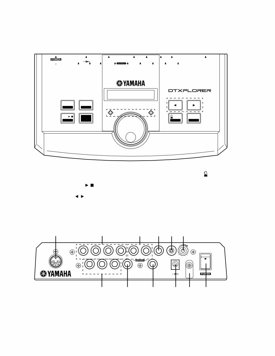
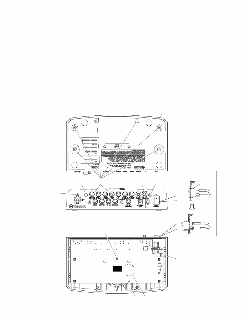
DTXPLORER 4 ■ PANEL LAYOUT q w e r t Drum Kit Button (DRUM KIT) Click Button (CLICK) Song Button (SONG / ) Shift Button (SHIFT) Select Buttons ( , ) y u i o !0 Metronome ON/OFF Button ( ON/OFF) Save/Enter Button (SAVE/ENT) LCD Display Click Lamp Jog Dial SAVE/ENT ON/OFF UTILITY TAP CLICK CLICK GRV.CHECK DRUM KIT TRIGGER TRIGGER SONG SONG DRUM MUTE / BEAT CLICK 1 SNARE 2 TOM1 3TOM2 4 TOM3 DC IN 12V 5 RIDE PHONES 6 CRASH 7 HI HAT 8 KICK/9 L/MONO R MIDI OUT HI HAT CONTROL AUX IN VOLUME STANDBY ON DRUM TRIGGER MODULE SHIFT SHIFT * DTXPLORER * * Welcome! * q o !0 i w e r y u t 1 SNARE 1 SNARE 2 TOM1 2 TOM1 3TOM2 3TOM2 4 TOM3 4 TOM3 DC IN 12V DC IN 12V 5 RIDE 5 RIDE PHONES PHONES 6 CRASH 6 CRASH 7 HI HAT 7 HI HAT 8 KICK/9 8 KICK/9 MIDI OUT MIDI OUT HI HAT CONTROL HI HAT CONTROL AUX IN AUX IN VOLUME VOLUME STANDBY ON L/MONO L/MONO R MIN MAX !1 !2 !3 !4 !5 !6 !7 !8 !9 @0 @1 MIDI OUT Jack Trigger Input Jacks (1 SNARE thru 7 HI HAT) Trigger Input jack (8 KICK/9) Hi-Hat Controller Jack (HI HAT CONTROL) Output Jacks (OUTPUT L/MONO, R) Head Phone Jack (PHONES) AUX IN Jack Master Volume (VOLUME) Power Supply Jack (DC IN 12V) Cord Hook Power Switch (POWER) !1 !2 !5 !2 !4 !3 !6 !7 !8 !9 @0 @1 ● Top Panel ● Rear Panel
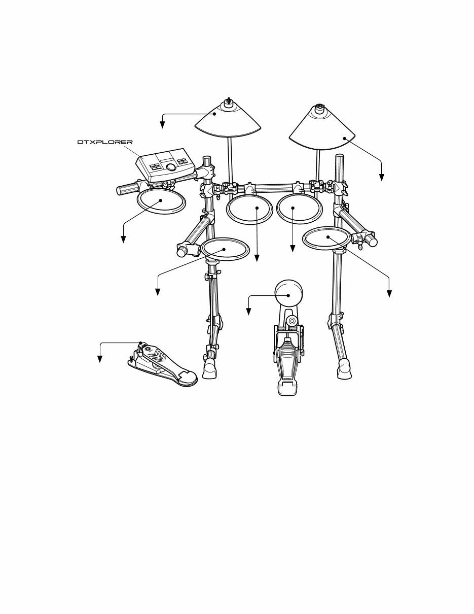
5 DTXPLORER ■ CONNECTING THE PADS to 8 KICK/9 to 1 SNARE to 2 TOM1 to 3 TOM2 to 4 TOM3 to 5 RIDE to 6 CRASH to 7 HI HAT to HI HAT CONTROL
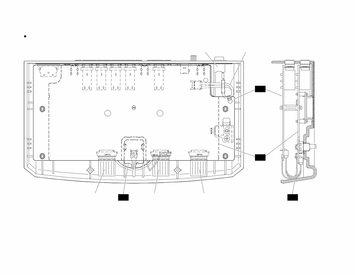
DTXPLORER 6 ■ UNIT LAYOUT and WIRING Inside View to PN-CN303 to DM-CN101 Power Switch Assembly to PN-CN302 to PN-CN301 CN3 CN101 CN2 CN1 PN DM RE RE
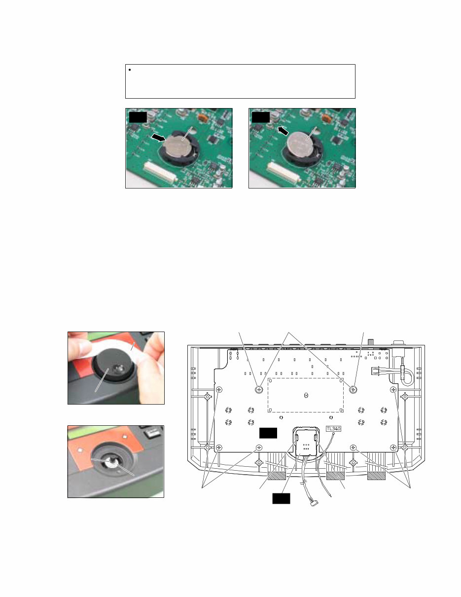
DTXPLORER 8 ■ DISASSEMBLY PROCEDURE 1. Bottom Case Assembly (time required: about 1 minutes) 1-1 Remove the eight (8) screws marked [30a] and the screw marked [50]. The bottom case assembly can then be removed. (Fig. 1) 2. DM Circuit board (time required: about 2 minutes) 2-1 Remove the bottom case. (See Procedure 1.) 2-2 Remove the screw marked [30b] and the spacer support. The DM circuit board can then be removed. (Fig. 1 & 2) * To remove the DM circuit board, remove the cord holder marked [A] and the solder marked [B]. * When reinstalling the bottom case assembly and DM circuit board, first install the screw marked [30b]. (Fig. 2) [30]: Bind Head Tapping Screw-B 3.0x12 MFZN2BL (VQ074600) [50]: Bind Head Tapping Screw-B 3.0x12 MFZN2BL (VQ074600) (Fig. 1) 3. Power Switch Assembly (time required: about 1 minutes) 3-1 Remove the bottom case assembly. (See Procedure 1.) 3-2 Remove the DM circuit board. (See Procedure 2.) * Remove the power switch assembly while holding down the stopper marked [C]. Bottom case assembly Lithimu Battery [30a] [30c] [30b] Spacer support [50] [30c] DM [C] Power switch assembly [A] [B]
9 DTXPLORER 4. RE Circuit Board Assembly (time required: about 2 minutes) 4-1 Remove the bottom case assembly. (See Procedure 1.) 4-2 Remove the DM circuit board. (See Procedure 2.) 4-3 Remove the jog dial, the nut marked [D] and the washer marked [E]. Then expand the hook marked [F] and remove the RE circuit board. (Fig. 3)(Photo 3 & 4) [30]: Bind Head Tapping Screw-B 3.0x12 MFZN2BL (VQ074600) [T30]: Bind Head Tapping Screw-B 3.0x8 MFZN2BL (EP600190) (Fig. 3) (Photo 4) (Photo 3) (Photo 2) (Photo 1) 5. PN Circuit Board Assembly (time required: about 3 minutes) 5-1 Remove the bottom case assembly. (See Procedure 1.) 5-2 Remove the DM circuit board. (See Procedure 2.) 5-3 Remove the two (2) screws marked [30c], the eight (8) screws marked [T30]. The PN circuit board assembly can then be removed. (Fig. 1 & 3) * Use some force to remove the PN circuit board after removing the screws from the PN circuit board. * In order to reinstall the PN circuit board, use first the screw marked [G] and then the screw marked [H]. (Fig. 3) [T30] [G] [H] With washer [T30] [T30] Battery VN103500 (CR2032) Notice for back-up battery removal Push the battery as shows in photo 1 & 2, then the battery will pop up. RE PN [D] [D] [E] [E] Jog dial Jog dial DM DM Lithium battery Lithium battery Lithium battery Lithium battery Push Push Take out Take out [F] [F] Paper etc. Paper etc.
DTXPLORER 10 ■ LSI PIN DESCRIPTION PIN No. NAME I/O FUNCTION PIN No. NAME I/O FUNCTION 1 2 3 4 5 6 7 8 9 10 11 12 13 14 15 16 17 18 19 20 21 22 23 24 25 26 27 28 29 30 31 32 33 34 35 36 37 38 39 40 41 42 43 44 45 46 47 48 49 50 51 52 53 54 55 56 57 58 59 60 61 62 63 64 65 66 67 68 69 70 71 72 73 74 75 76 77 78 79 80 81 82 83 84 ICN RFCLKI TM2 AVDD_PLL AVSS_PLL MODE0 VCC7 GND8 XIN XOUT MODE1 TEST0 TESTON AN0-P40 AN1-P41 AN2-P42 AN3-P43 AVDD_AN AVSS_AN TXD0 TXD1 EXCLK SMD11 SMD4 SMD3 SMD12 SMD10 SMD5 SMD2 SMD13 SMD9 SMD6 SMD1 SMD14 VCC35 GND36 SMD8 SMD7 SMD0 SMD15 SOE SWE SRAS SCAS REFRESH CS0 SMA0 SMA16 VCC49 GND50 SMA1 SMA15 SMA2 SMA14 SMA3 SMA13 SMA4 SMA12 SMA5 GND60 VCC61 SMA11 SMA6 SMA10 SMA7 SMA9 SMA17 SMA8 SMA18 SMA19 SMA20 SMA21 SMA22 SMA23 CMA20 CMA19 VCC77 GND78 CMA18 CMA17 CMA5 CMA6 CMA4 CMA7 I I I I I O I I I I I I I O O I I/O I/O I/O I/O I/O I/O I/O I/O I/O I/O I/O I/O I/O I/O I/O I/O O O O O O O O O O O O O O O O O O O O O O O O O O O O O O O O O O O O O O O O Initial clear PLL Clock PLL Control Power supply Ground SWX dual mode Power supply Ground crystal oscillator crystal oscillator SWX separate mode TEST pin TEST pin A/D converter Power supply Ground for MIDI or TO-HOST for MIDI Crystal oscillator Wave memory data bus Power supply Ground Wave memory data bus read signal write signal RAS signal CAS signal REFRESH signal CS signal Memory address bus Memory address bus Power supply Ground Memory address bus Ground Power supply Memory address bus Program address bus Program address bus Power supply Ground Program address bus 85 86 87 88 89 90 91 92 93 94 95 96 97 98 99 100 101 102 103 104 105 106 107 108 109 110 111 112 113 114 115 116 117 118 119 120 121 122 123 124 125 126 127 128 129 130 131 132 133 134 135 136 137 138 139 140 141 142 143 144 145 146 147 148 149 150 151 152 153 154 155 156 157 158 159 160 161 162 163 164 165 166 167 168 CMA3 CMA8 CMA2 CRD CMA1 CUB VCC91 GHND92 CS1 CMA0 CLB CMA12 CMA11 CMA10 CMA9 GND100 CWE CMA16 CMA15 CMA14 CMA13 CMD8 CMD7 CMD9 CMD6 CMD10 CMD5 CMD11 CMD4 CMD12 CMD3 CMD13 CMD2 CMD14 VCC119 GND115 CMD1 CMD15 CMD0 CMA21 PDT15 PDT14 PDT13 PDT12 PDT11 PDT10 PDT9 PDT8 VCC133 GND134 PDT7 PDT6 PDT5 PDT4 PDT3 PDT2 PDT1 PDT0 VCA143 GND144 PAD2 PAD1 PAD0 VCC148 GND149 PCS PWR PRD RXD0 RXD1 SCLKI ADIN ADLR DO0 DO1 SYSCLK VCC161 GND162 WCLK QCLK BCLK SYI IRQ0 NMI O O O O O O O O O O O O O O O O O O I/O I/O I/O I/O I/O I/O I/O I/O I/O I/O I/O I/O I/O I/O I/O I/O O I/O I/O I/O I/O I/O I/O I/O I/O I/O I/O I/O I/O I/O I/O I/O I/O I I I I I I I I I I O O O O O O O I I I read signal Program address bus high byte effective signal Power supply Ground CS signal Program address bus low byte effective signal Program address bus Ground write signal Program address bus Program memory Data bus Power supply Ground Program address bus SWX access data bus Power supply Ground SWX access data bus Power supply Ground SWX access address bus Power supply Ground Chip select write enable read enable for Midi or TO-HOST for Midi or Key scan EXT Clock A/D converter A/D converter LR clock DAC DAC 1/2 clock Power supply Ground for DAC LR clock 1/12 clock IIS-DAC clock Synch signal Interrupt request Interrupt request ● HG73C205AFD (XU947C00) SWX00B TONE GENERATOR DM: IC1
Are you experiencing issues with your Yamaha DTXPLORER Drum Trigger Module? Why spend a fortune on repairs or replacements when you can take matters into your own hands?
This comprehensive service and repair manual is the same one utilized by Official Certified Yamaha Technicians, equipping you with the knowledge to effectively troubleshoot and mend your Drum Trigger Module!
Contents:
SPECIFICATION
PANEL LAYOUT
CONNECTING THE PADS
UNIT LAYOUT and WIRING
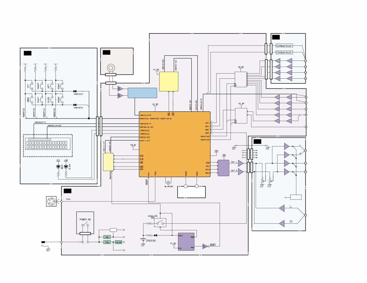
BLOCK DIAGRAM
DISASSEMBLY PROCEDURE
LSI PIN DESCRIPTION
IC BLOCK DIAGRAM
CIRCUIT BOARDS
TEST PROGRAM
ERROR MESSAGES
MIDI IMPLEMENTATION CHART
OVERALL CIRCUIT DIAGRAM
PARTS LIST
This service manual is replete with detailed images and step-by-step instructions, ensuring you can effectively service and repair your device with ease!
It's important to note that this is the official service and repair manual in PDF format, guaranteeing high resolution and exceptional print quality for the pages you require!
Instant Access:
Upon payment, you will gain immediate access to your manual! No shipping fees or waiting for postal delivery – you can commence your repairs promptly!
Specifications:
Language: English
Format: PDF
Pages: 38
Platform: Windows and MAC
Recently Viewed
5,521,897Happy Clients
2,594,462eManuals
1,120,453Trusted Sellers
15Years in Business
Price:
Actual Price:
Yamaha DTXPLORER Drum Trigger Module Service Manual & Repair Guide