



■CONTENTS
SPECIFICATIONS .................................................................................... 3
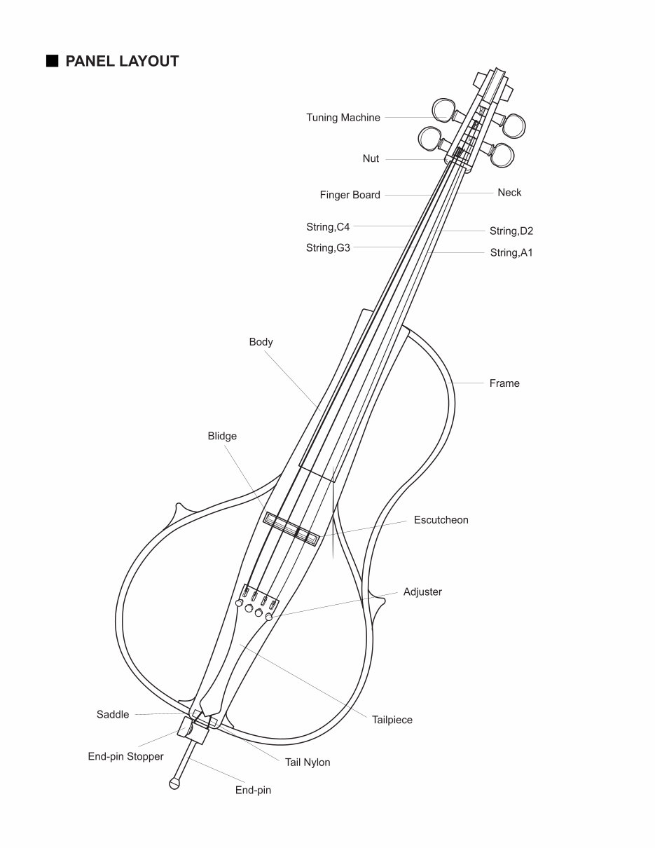
PANEL LAYOUT ........................................................................................ 4
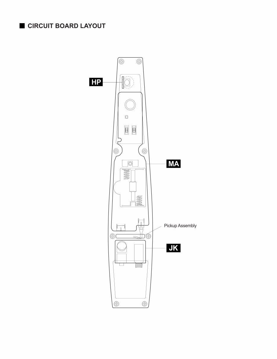
CIRCUIT BOAD LAYOUT ......................................................................... 6
BLOCK DIAGRAM ................................................................................... 7
DISASSEMBLY PROCEDURE ................................................................. 8
LSI PIN DESCRIPTION & IC BLOCK DIAGRAM ................................. 9
CIRCUIT BOARDS ................................................................................ 10
INSPECTION ......................................................................................... 12
MECHANICAL NOISE CHECK POINT ................................................... 13
OVERALL CIRCUIT DIAGRAM ............................................................ 14
SERVICE MANUAL
GD 011438
HAMAMATSU,JAPAN
1.82K-702 I Printed in Japan’98.11
PARTS LIST

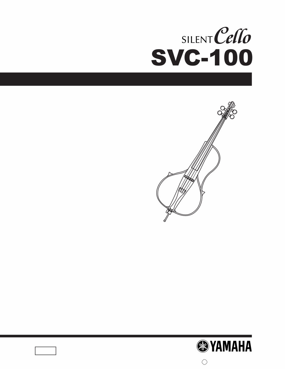
SVC-100
2
IMPORTANT NOTICE
This manual has been provided for the use of authorized Yamaha Retailers and their service personnel. It has been
assumed that basic service procedures inherent to the industry, and more specifically Yamaha Products, are already
known and understood by the users, and have therefore not been restated.
WARNING: Failure to follow appropriate service and safety procedures when servicing this product may
result in personal injury, destruction of expensive components and failure of the product to per
form as specified. For these reasons, we advise all Yamaha product owners that all service
required should be performed by an authorized Yamaha Retailer or the appointed service rep-
resentative.
IMPORTANT: This presentation or sale of this manual to any individual or firm does not constitute authoriza-
tion, certification, recognition of any applicable technical capabilities, or establish a principal-
agent relationship of any form.
The data provided is believed to be accurate and applicable to the unit(s) indicated on the cover. The research
engineering, and service departments of Yamaha are continually striving to improve Yamaha products. Modifications
are, therefor, inevitable and changes in specification are subject to change without notice or obligation to retrofit.
Should any discrepancy appear to exist, please contact the distributor's Service Division.
WARNING: Static discharges can destroy expensive components. Discharge any static electricity you body
may have accumulated by grounding yourself to the ground buss in the unit (heavy gauge black
wires connect to this buss).
IMPORTANT: Turn the unit OFF during disassembly and parts replacement. Recheck all work before you
apply power to the unit.
WARNING: CHEMICAL CONTENT NOTICE!
The solder used in the production of this product contains LEAD. In addition, other electrical / electronic and / or
plastic (where applicable) components may also contain traces of chemicals found by the California Health and
Welfare Agency (and possibly other entities) to cause cancer and / or birth defects or other reproductive harm.
DO NOT PLACE SOLDER, ELECTRICAL / ELECTRONIC OR PLASTIC COMPONENTS IN YOUR MOUTH FOR
ANY REASON WHAT SO EVER!
Avoid prolonged, unprotected contact between solder and your skin! When soldering, do not inhale solder fumes or
expose eyes to solder / flux vapor!
If you come in contact with solder or components located inside the enclosure of this product, wash your hands
before handling food.

3
SVC-100
Pole Maple
Body Spluce
Finger Board・Tuning Machine Ebony
Nut Maple (PANDI)
Frame Formed plywood
Tailpiece Adjuster with 4Piece (Wittnner-made)
String (Pole end Type) Spirocore String
Sensor Newly developed pickup
Electricity ・ Headphone Output
・ AUX IN (with volume adjuster)
・ LINE OUT
・ VOLUME
・ REVERB switch (ROOM/HALL/HALL2)
・ POWER switch (OFF/ON/REV.ON)
Power Size AA dry battery×2 /Serves as a Power Adapter
Power Supply Manganese Batteries
(Continuous-use time) ・POWER SWITCH:ON
15hours
・POWER SWITCH:REV.ON
2.5hours
Alkali Batteries
・POWER SWITCH:ON
35hours
・POWER SWITCH:REV.ON
10hours
String Size 695mm
Dimentions 1260(L)×430(W) ×242(H)mm (without the Chest Plate)
Weight 3.5Kg (with batteries and the Chest Plate)
Output Refer to the INSPECTION selection of this manual.
SVC-100
4
•
Front View
5
SVC-100
•
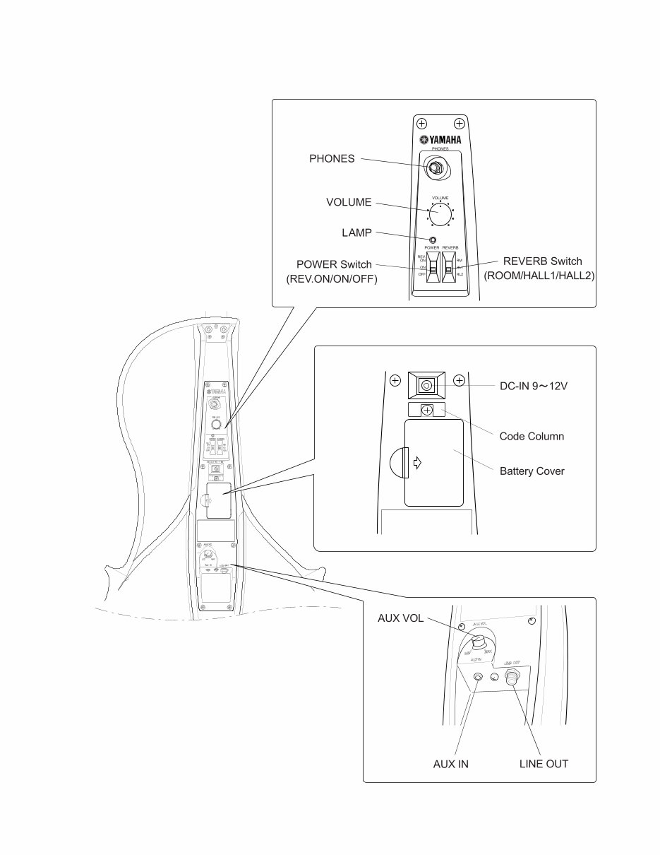
Rear View
SVC-100
6
•
Rear View
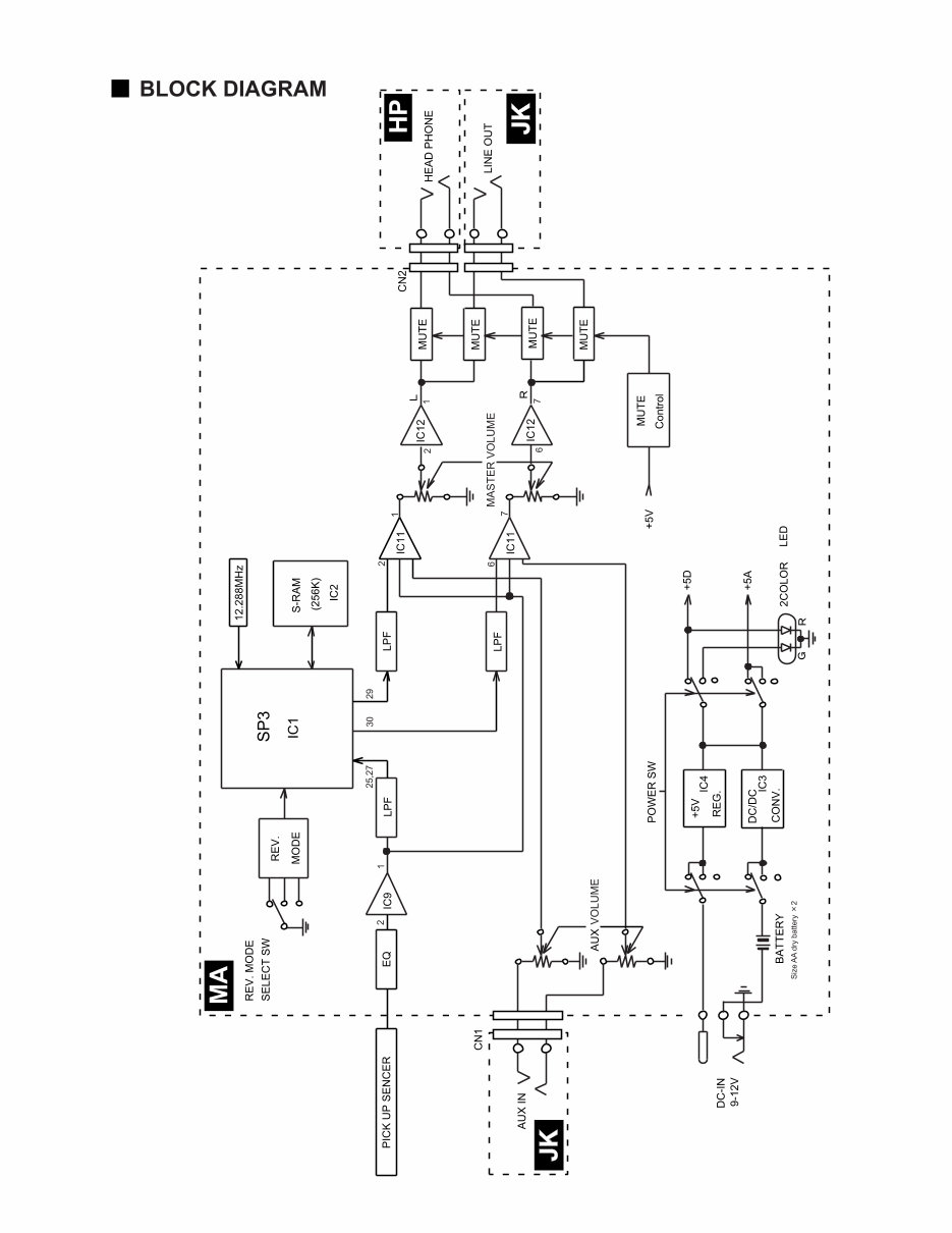
7
SVC-100
KEC-54166
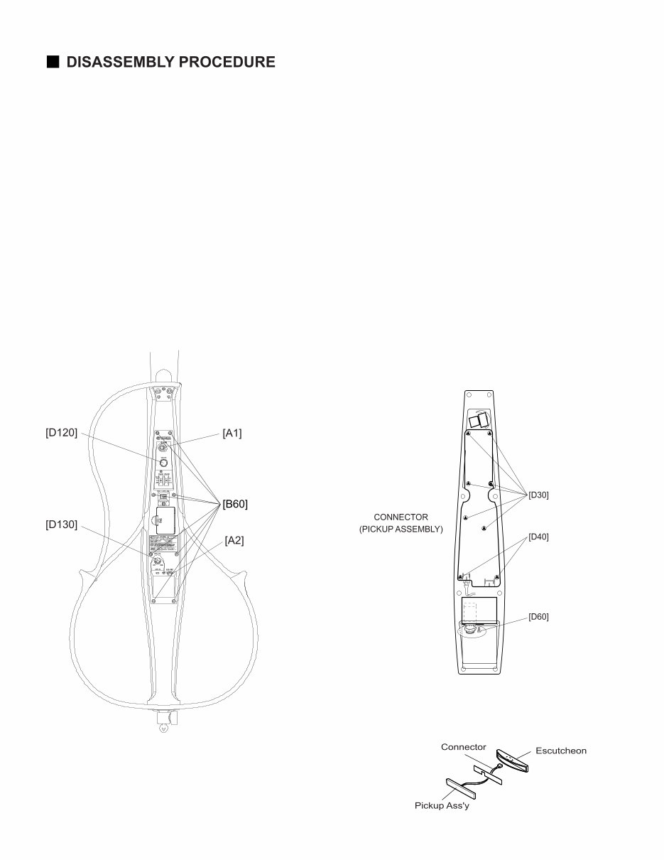
SVC-100
8
Preparations
Make the following preparations;
• Turn off the power switch.
• Remove the battery cover and battery.
• Turn each peg and loosen the string. The bridge can then be removed.
(Fig. 1)
(Fig. 3)
(Fig. 2)
[B60]: Bind Head Tapping Screw-1 3.0X6 MFZN2BL (V327300)
[A]: Nut
[D30]: Bind Head Tapping Screw-P PW3.0X10 MFZN2BL (VU425500)
[D40]: Bind Head Screw SP3.0X6 MFC2BL (VC365900)
[D60]: Bind Head Screw SP3.0X6 MFC2BL (VC365900)
1. MA circuit board
1-1 Remove the eight (8) screws marked [B60].
(Fig. 1)
1-2 Disconnect the pickup assembly connector
from the MA circuit board.
1-3 Remove the knob marked [D120].
1-4 Remove the six (6) screws marked [D30] and
the two (2) screws marked [D40].
The MA circuit board can then be removed.
(Fig. 2)
* When removing the control panel, be sure
to not hook up the battery minus terminal,
which is located in the battery case and is
installed on the MA circuit board.
2. HP circuit board
2-1 Remove the nut marked [A1]. The HP circuit
board can then be removed. (Fig. 1)
3. JK circuit board
3-1 Remove the knob marked [ D130].
3-2 Remove the nut marked [A2]. (Fig. 1)
3-3 Remove the screw marked [D60]. The JK circuit
board can then be removed.
4. Pickup Assembly
4-1 Push the pickup cable through the base hole and
remove the pickup assembly together with the
escutcheon. (Fig. 3)
* When removed the pickup assembly together
with the escutcheon, be caraful sure not to
damage the pickup assembly.
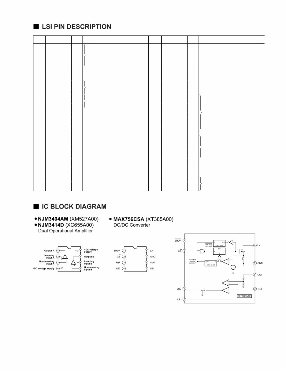
9
SVC-100
●
●●
●
YSS234 (XN299A00) Digital Sound Processor
PIN
NO.
NAME I/O FUNCTION
PIN
NO.
NAME I/O FUNCTION
1 MD4 I/O 33 AVDD - DC A+5Vs bus
2 MD3 I/O 34 VDD - DC D+5V
3 MD0 I/O External RAM interface data 35 TST0 - DC D+5V
4 MD1 I/O 36 TST1 - DC D+5V
5 MD2 I/O 37 DOEN - DC D+5V
6 MCKO O Master clock output 38 SDO1 O N.C.
7 XO O Crystal oscillator connection 39 SDO0 O N.C.
8 XI I Crystal oscillator connection 40 WC O N.C.
9 ER0 I 41 BCO O N.C
10 ER1 I Eary refrection preset select 42 MA0 O
11 ER2 I 43 MA1 O
12 REV0 I 44 MA2 O
13 REV1 I Effect select 45 MA3 O
14 REV2 I 46 MA4 O
15 MUTEN I DC D+5V 47 MA5 O External RAM interface address
16 ICN I Initial clear 48 MA6 O
17 PRG I DC D+5V 49 MA7 O
18 MODE I Preset mode (H=DC +5V) 50 MA12 O
19 VSS - Ground 51 MA14 O
20 AVSS - Ground 52 VSS - Ground
21 CVA - N.C. 53 MA10 O
22 AORL O N.C. 54 MA011 O
23 AORR O N.C. 55 MA09 O External RAM interface address
24 CHL I Sample hold capacitor connection 56 MA8 O
25 AIL I Lch ADC input 57 MA13 O
26 VDD - DC D+5V 58 VDD - DC D+5V
27 AIR I Rch ADC input 59 WEN I Write enable
28 CHR I Sample hold capacitor connection 60 OEN I Output enable
29 AOFL O Lch DAC output 61 CEN I Chip select
30 AOFR O Rch DAC output 62 MD7 I/O
31 AVDD - DC A+5V 63 MD6 I/O External RAM interface data
32 CVB I Rch midpoint voltage 64 MD5 I/O
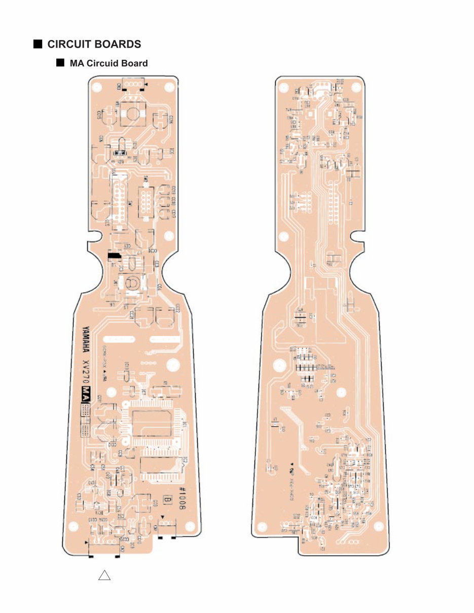
SVC-100
10
DC-IN VOLUME
to PIC UP SENCOR
to HP-CN1
to JK-CN1
POWER SW
REVERB
(Pattern side) (Component side)
MA:ENA-V286330 2
You're Reading a Preview
What's Included?
 Lifetime Access
Fast Download Speeds
Online & Offline Access
Access PDF Contents & Bookmarks
Full Search Facility
Print one or all pages of your manual
$31.99
Yamaha SVC-100 Silent Cello Service Manual
Viewed 54 Times Today

What's Included?
Lifetime Access
Fast Download Speeds
Online & Offline Access
Access PDF Contents & Bookmarks
Full Search Facility
Print one or all pages of your manual
$31.99

Secure transaction
What's Included?
Lifetime Access
Fast Download Speeds
Online & Offline Access
Access PDF Contents & Bookmarks
Full Search Facility
Print one or all pages of your manual
Description
The Yamaha SVC-100 Silent Cello Service Manual is an essential resource for both professional mechanics and DIY enthusiasts. It provides detailed technical information and instructions for servicing and repairing the Yamaha SVC-100 Silent Cello.
- Language: English
- Format: PDF
- Platform: Windows and Mac
The manual covers a wide range of topics including panel layout, circuit board layout, block diagram, disassembly procedure, LSI pin description & IC block diagram, inspection, mechanical noise check point, overall circuit diagram, and parts list.
Whether you are a professional technician or a passionate cello player, this manual is an invaluable tool for understanding and maintaining the Yamaha SVC-100 Silent Cello.


