ORDER NO. PIONEER CORPORATION 4-1, Meguro 1-chome, Meguro-ku, Tokyo 153-8654, Japan PIONEER ELECTRONICS SERVICE, INC. P.O. Box 1760, Long Beach, CA 90801-1760, U.S.A. PIONEER EUROPE N.V. Haven 1087, Keetberglaan 1, 9120 Melsele, Belgium PIONEER ELECTRONICS ASIACENTRE PTE. LTD. 253 Alexandra Road, #04-01, Singapore 159936 PIONEER CORPORATION 2000 c Type Model Power Requirement Remarks CMX-5000 CU-V160 KUC AC120V TL AC110-240V WY AC220-240V CMX-5000 RRV2260 1. SAFETY INFORMATION ....................................... 2 2. EXPLODED VIEWS AND PARTS LIST ................. 4 3. BLOCK DIAGRAM AND SCHEMATIC DIAGRAM ... 12 4. PCB CONNECTION DIAGRAM ........................... 45 5. PCB PARTS LIST ................................................ 59 6. ADJUSTMENT ..................................................... 64 CONTENTS 7. GENERAL INFORMATION ................................ 66 7.1 DIAGNOSIS .................................................. 66 7.1.1 TEST MODE ......................................... 66 7.1.2 POWER ON SEQUENCE .................... 71 7.1.3 DISASSEMBLY .................................... 72 7.2 PARTS .......................................................... 75 7.2.1 IC .......................................................... 75 7.2.2 DISPLAY ............................................... 78 8. PANEL FACILITIES AND SPECIFICATIONS .... 80 T – IZK FEB. 2000 Printed in Japan CU-V160 THIS MANUAL IS APPLICABLE TO THE FOLLOWING MODEL(S) AND TYPE(S). COMPACT DISC PLAYER REMOTE CONTROLLER POWER EJECT DISC APLAYER ' 0 EJECT DISC BPLAYER CMX-5000 DJ TWIN CD PLAYER 0 A B CUE REV FWD SEARCH PLAY/PAUSE EJECT TRACK SEARCH LOOP OUT EXIT OUT ADJUST OUT ADJUST RELOOP TIME MODE TEMPO MT MASTER TEMPO 0 ±6/±10/±16 AUTO CUE IN/REALTIME CUE 6 0 CUE REV FWD SEARCH PLAY/PAUSE EJECT TRACK SEARCH LOOP OUT EXIT RELOOP TIME MODE TEMPO MT MASTER TEMPO 0 ±6/±10/±16 AUTO CUE IN/REALTIME CUE 6 0 4 ¢ 1 ¡ 4 ¢ 1 ¡ AUTO MIX PLAY BPM SYNC SHORTTIME A B TRACK DISC PROGRAM BPM NEXT CMX-5000 CU-V160
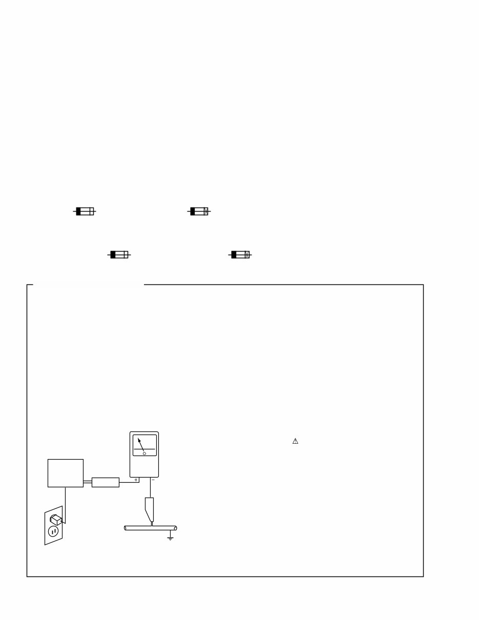
2 CMX-5000, CU-V160 1. SAFETY INFORMATION This service manual is intended for qualified service technicians ; it is not meant for the casual do-it- yourselfer. Qualified technicians have the necessary test equipment and tools, and have been trained to properly and safely repair complex products such as those covered by this manual. Improperly performed repairs can adversely affect the safety and reliability of the product and may void the warranty. If you are not qualified to perform the repair of this product properly and safely, you should not risk trying to do so and refer the repair to a qualified service technician. WARNING This product contains lead in solder and certain electrical parts contain chemicals which are known to the state of California to cause cancer, birth defects or other reproductive harm. Health & Safety Code Section 25249.6 – Proposition 65 NOTICE (FOR CANADIAN MODEL ONLY) Fuse symbols (fast operating fuse) and/or (slow operating fuse) on PCB indicate that replacement parts must be of identical designation. REMARQUE (POUR MODÈLE CANADIEN SEULEMENT) Les symboles de fusible (fusible de type rapide) et/ou (fusible de type lent) sur CCI indiquent que les pièces de remplacement doivent avoir la même désignation. ANY MEASUREMENTS NOT WITHIN THE LIMITS OUTLINED ABOVE ARE INDICATIVE OF A POTENTIAL SHOCK HAZARD AND MUST BE CORRECTED BEFORE RETURNING THE APPLIANCE TO THE CUSTOMER. 2. PRODUCT SAFETY NOTICE Many electrical and mechanical parts in the appliance have special safety related characteristics. These are often not evident from visual inspection nor the protection afforded by them necessarily can be obtained by using replacement components rated for voltage, wattage, etc. Replacement parts which have these special safety characteristics are identified in this Service Manual. Electrical components having such features are identified by marking with a on the schematics and on the parts list in this Service Manual. The use of a substitute replacement component which does not have the same safety characteristics as the PIONEER recommended replacement one, shown in the parts list in this Service Manual, may create shock, fire, or other hazards. Product Safety is continuously under review and new instructions are issued from time to time. For the latest information, always consult the current PIONEER Service Manual. A subscription to, or additional copies of, PIONEER Service Manual may be obtained at a nominal charge from PIONEER. 1. SAFETY PRECAUTIONS The following check should be performed for the continued protection of the customer and service technician. LEAKAGE CURRENT CHECK Measure leakage current to a known earth ground (water pipe, conduit, etc.) by connecting a leakage current tester such as Simpson Model 229-2 or equivalent between the earth ground and all exposed metal parts of the appliance (input/output terminals, screwheads, metal overlays, control shaft, etc.). Plug the AC line cord of the appliance directly into a 120V AC 60Hz outlet and turn the AC power switch on. Any current measured must not exceed 0.5mA. (FOR USA MODEL ONLY) Leakage current tester Reading should not be above 0.5mA Device under test Test all exposed metal surfaces Also test with plug reversed (Using AC adapter plug as required) Earth ground AC Leakage Test
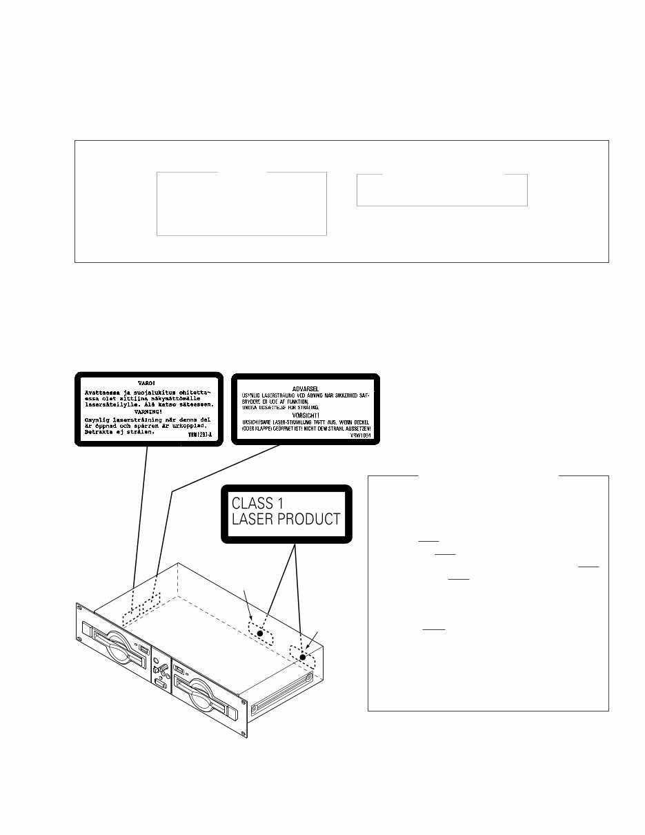
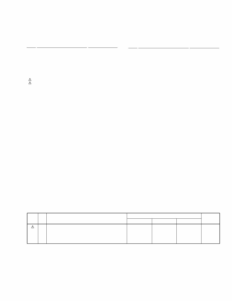
3 CMX-5000, CU-V160 (Printed on the Rear Panel) WY type TL type Additional Laser Caution 1. Laser Interlock Mechanism The position of the switch (S1) for detecting loading completion is detected by the system microprocessor, and the design prevents laser diode oscillation when the switch is not in LPS1 terminal side (when the mechanism is not clamped and LPS1 signal is high level.) Thus, the interlock will no longer function if the switch is deliberately set to LPS1 terminal side. ( if LPS1 signal is low level ). In the test mode∗ the interlock mechanism will not function. Laser diode oscillation will continue, if pin 2 of AN8847SB (IC201) on the CDPB Assy is connected to GND, or pin 19 of IC201 (LDON) is connected to low level (ON), or else the terminals of Q201 are shorted to each other (fault condition). 2. When the cover is opened, close viewing of the objective lens with the naked eye will cause exposure to a Class 1 laser beam. ∗ : Refer to page 69. IMPORTANT THIS PIONEER APPARATUS CONTAINS LASER OF CLASS 1. SERVICING OPERATION OF THE APPARATUS SHOULD BE DONE BY A SPECIALLY INSTRUCTED PERSON. LASER DIODE CHARACTERISTICS MAXIMUM OUTPUT POWER: 5 mW WAVELENGTH: 780 – 785 nm LABEL CHECK (for WY and TL types)
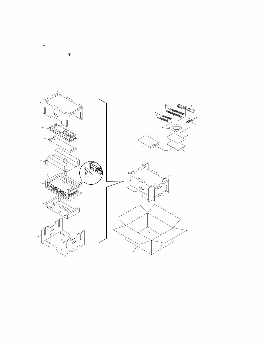
4 CMX-5000, CU-V160 2.1 PACKING 2. EXPLODED VIEWS AND PARTS LIST NOTES: • Parts marked by "NSP" are generally unavailable because they are not in our Master Spare Parts List. • The mark found on some component parts indicates the importance of the safety factor of the part. Therefore, when replacing, be sure to use parts of identical designation. • Screws adjacent to mark on the product are used for disassembly. 1 9 2 3 21 8 4 5 20 7 19 16 17 11 22 (TL Type Only) 12 15 13 10 (KUC Type Only) 6
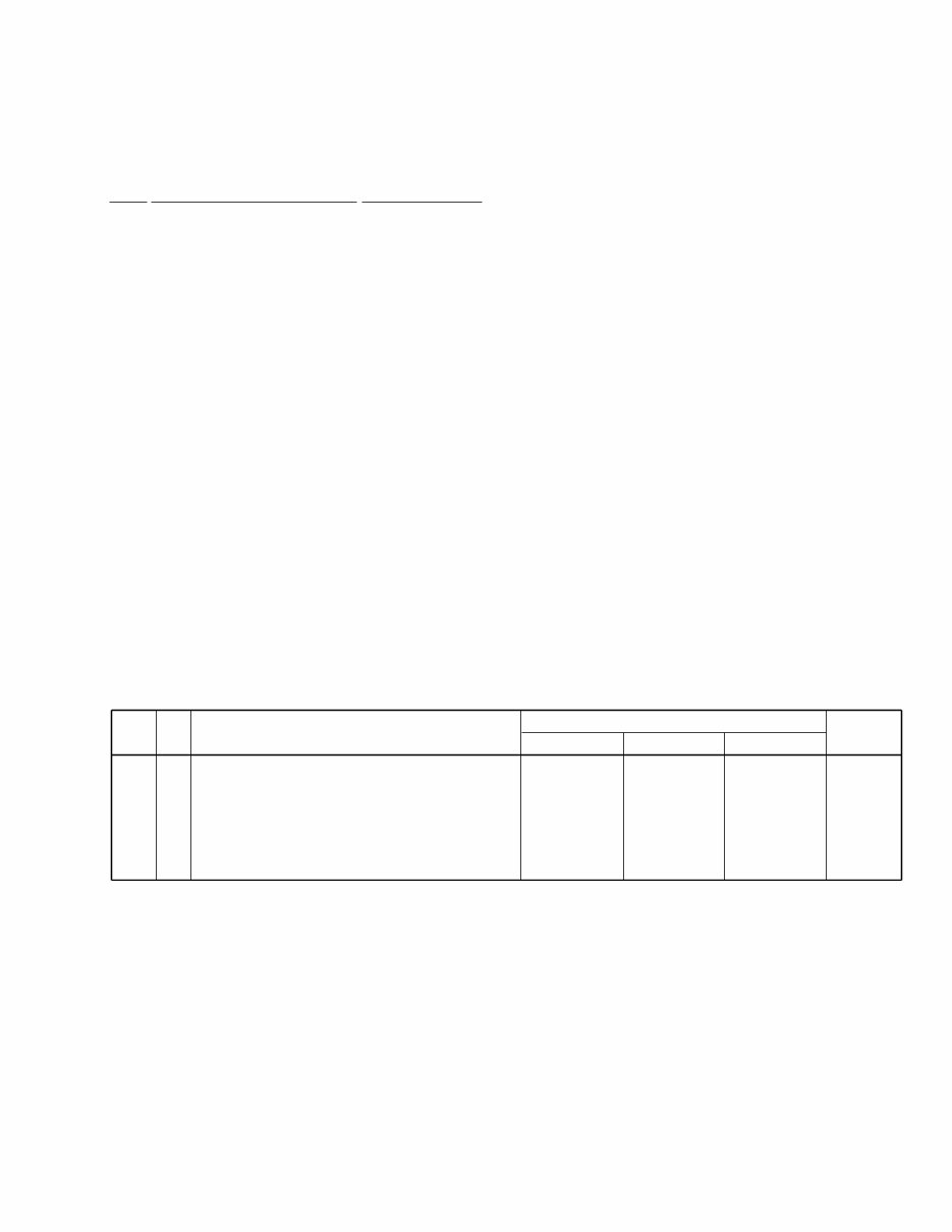
5 CMX-5000, CU-V160 (1) PACKING PARTS LIST Mark No. Description Part No. 1 Pad A DHA1448 2 Pad B DHA1449 3 Pad C DHA1450 4 Pad D DHA1451 5 Pad E DHA1474 6 Packing Case See Contrast table (2) NSP 7 Caution SG DRM1199 8 Sheet RHX1006 9 Mirror Mat Sheet Z23-026 (550 × 550 × 0.5) NSP 10 Limited Warranty See Contrast table (2) 11 Specialized Connection Cable DDE1115 for The Remote Controller 12 Forced Ejection Pin DEX1013 13 Operating Instructions See Contrast table (2) 14 • • • • • 15 Caution Tag AP DRW1897 16 Control Cord PDE1247 17 Audio Cable (L=1.5m) VDE1033 18 • • • • • 19 Polyethylene Bag Z21-038 (0.03 × 230 × 340) NSP 20 Silica Gel AEN7001 NSP 21 Polyethylene Bag AHG7047 22 Adaptor for 8cm discs See Contrast table (2) (2) CONTRAST TABLE CMX-5000/KUC, TL and WY are constructed the same except for the following : Mark No. Symbol and Description Part No. Remarks KUC Type TL Type WY Type NSP 6 10 13 13 13 22 Packing Case Limited Warranty Operating Instructions (English) Operating Instructions (English/Spanish/Chinese) Operating Instructions (English/French/German/Italian/Dutch/Spanish) Adaptor for 8cm discs DHG1961 ARY7043 DRB1254 Not used Not used Not used DHG1960 Not used Not used DRB1256 Not used DEX1012 DHG1953 Not used Not used Not used DRB1255 Not used
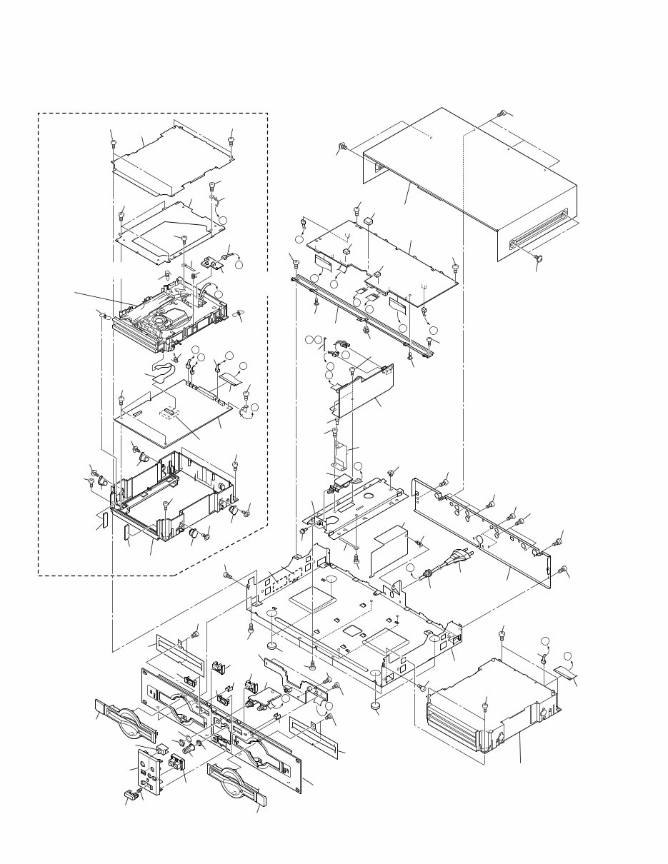
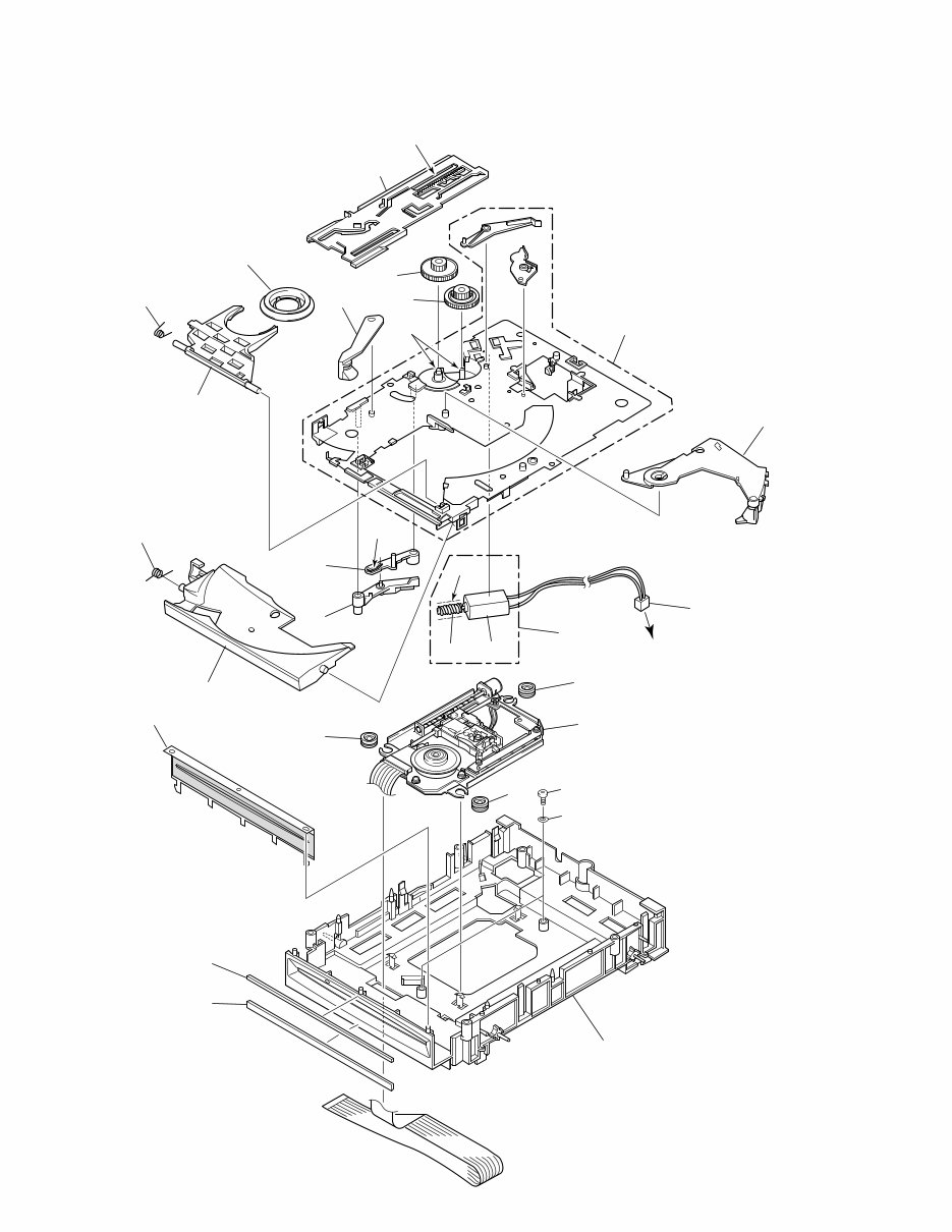
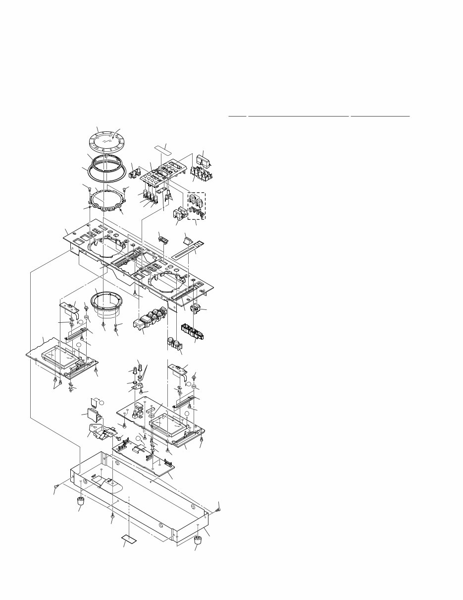
6 CMX-5000, CU-V160 2.2 EXTERIOR I H G H G F E E F J A B L K D C K L B A J I A PLAYER B PLAYER This component is same as A PLAYER. 56 36 56 56 37 56 56 51 15 14 11 1 18 56 54 54 54 54 60 60 60 60 35 35 38 35 24 24 35 13 4 (A PLAYER) 5 (B PLAYER) 33 34 34 34 34 16 Refer to "2.3 SLOT-IN MECHANISM ASSY". 12 45 44 49 41 42 48 59 39 61 21 21 46 40 40 7 3 47 47 46 56 56 56 54 54 26 54 54 27 9 10 32 22 20 25 54 53 62 28 2 8 54 62 57 57 54 54 54 54 54 54 54 55 55 43 31 19 19 54 6 54 30 20 30 29 50 14 11 54 54 64 TL and WY Types Only 63 54 23 23 58 17 44 D D C C 52
7 CMX-5000, CU-V160 (1) EXTERIOR PARTS LIST Mark No. Description Part No. 1 CDPB ASSY DWG1540 2 PSWB ASSY DWS1301 3 SELB ASSY DWS1302 4 SLM1 ASSY DWS1303 5 SLM2 ASSY DWS1304 6 TRMB ASSY DWX2066 7 HPJB ASSY DWX2067 8 SW POWER SUPPLY ASSY DWR1330 9 AC Power Cord See Contrast table (2) 10 Strain Relief See Contrast table (2) 11 37P F•F•C/60V DDD1159 12 Earth Lead Unit DDF1010 13 SL Connecto Assy 3P DKP3403 14 Connector Assy 3P DKP3514 15 S Flexible Cable DNP1748 NSP 16 Slot-in Mechanism Assy DXA1845 17 Power Knob Spring DBH1469 18 Silicon Seat DEB1449 19 Rubber Spacer DEB1455 20 PCB Holder DEC1231 21 Bezel Sheet DEC2346 22 Power Supply Cover DEC2347 23 Insulator DEC2348 24 Bezel Cushion C DEC2350 25 Power Supply Shield DEC2391 NSP 26 Chassis DNA1253 27 Rear Panel See Contrast table (2) 28 Power Supply Plate DNF1637 29 PCB Frame DNH2446 NSP 30 PCB Holder PNW1861 NSP 31 Spacer VEC1585 32 PCB Spacer VEC2077 33 Earth Spring DBH1398 34 Float Spring DBH1428 35 Damper DEC2236 36 Cover A DNF1636 37 Mecha Holder DNH2339 38 Damper Stay DNK3751 39 VR Knob DAA1145 40 Eject Knob DAC1924 41 Slide SW Knob DAC1926 42 Monitor Select Knob DAC1939 43 Bonnet DNE1382 44 Front Bezel DNK3724 45 Power Knob DNK3725 46 Eject Guide DNK3727 47 Disc Indicator DNK3729 48 Front Panel Assy DXB1729 49 Function Panel Assy DXB1732 50 Nylon Rivet (3 × 4.5) RBM-003 51 Cord Clamper RNH-184 52 Binder ZCA-SKB90BK NSP 53 Cord Stopper ZCB-069Z 54 Screw BBZ30P060FZK 55 Screw BBZ40P060FZK 56 Screw BPZ30P080FMC 57 Screw BPZ30P080FZK 58 Washer DBE1010 59 Flange Nut DBN1004 60 Screw IPZ20P080FMC 61 Nut NKX2FUC 62 Screw PMH30P060FMC 63 Caution Label See Contrast table (2) NSP 64 Caution Label HE See Contrast table (2) (2) CONTRAST TABLE CMX-5000/KUC, TL and WY are constructed the same except for the following : Mark No. Symbol and Description Part No. Remarks KUC Type TL Type WY Type NSP 9 10 27 63 64 AC Power Cord Strain Relief Rear Panel Caution Label Caution Label HE ADG7024 CM-22C DNC1520 Not used Not used VDG1061 CM-22B DNC1519 VRW1094 VRW1297 VDG1061 CM-22B DNC1516 VRW1094 VRW1297 Mark No. Description Part No.
Is your Pioneer CMX-5000 CD Player letting you down?
Why replace or spend lots of money on repairs while you can do it yourself? This service and repair manual is used by the Official Certified Pioneer Technicians. It will help you to troubleshoot and repair your CD Player!
You will learn about:
Safety & Precautions
Product Specifications
Maintenance
Disassembly & Reassembly
Adjustments
System Diagrams
Exploded Views
Replacement Parts list
This manual is very detailed with colored pictures and step-by-step instructions on how to repair/service this device the best way there is! Please note this is the OFFICIAL service and repair manual in .PDF format, no scanned-in or bootlegged copy. This manual is made in high resolution, so when you print the pages you need it is all in great quality!
***INSTANT access*** After your payment, you will have instant access to your manual! No shipping fee, no waiting on postal delivery, you can start doing your repairs right away!
Specifications
Language: English
Format: .PDF
Pages: 82
Platform: Windows and MAC
Looking for a service manual but can't find it anywhere? Please contact us with your request! As you can see we've got one of the largest service manual databases out there, so a good chance we can help you out!