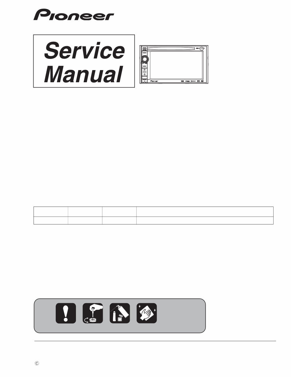
ORDER NO. PIONEER CORPORATION 1-1, Shin-ogura, Saiwai-ku, Kawasaki-shi, Kanagawa 212-0031, Japan PIONEER ELECTRONICS (USA) INC. P.O. Box 1760, Long Beach, CA 90801-1760, U.S.A. PIONEER EUROPE NV Haven 1087, Keetberglaan 1, 9120 Melsele, Belgium PIONEER ELECTRONICS ASIACENTRE PTE. LTD. 253 Alexandra Road, #04-01, Singapore 159936 PIONEER CORPORATION 2011 AVIC-X930BT/XNUC CRT4695 MULTIMEDIA AV NAVIGATION RECEIVER AVIC-X930BT /XNUC AVIC-X9310BT/XNUC NAVIGATION AV SYSTEM AVIC-F930BT/XNAU This service manual should be used together with the following manual(s): Model No. Order No. Mech. Module Remarks CX-3250 CRT4300 LS1 DVD Mech. Module : Circuit Descriptions, Mech. Descriptions, Disassembly For details, refer to "Important Check Points for Good Servicing". K-ZZZ MAR. 2011 Printed in Japan
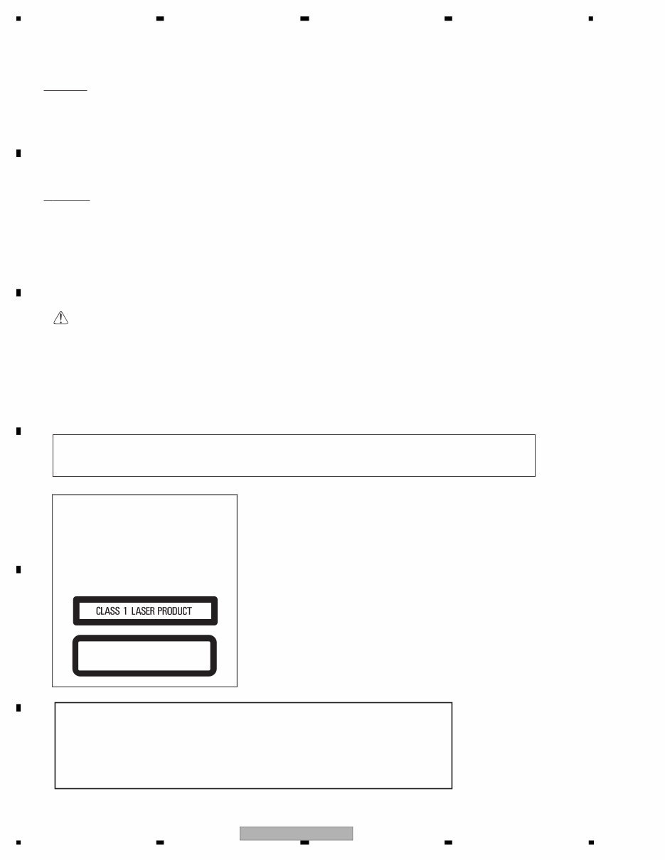
AVIC-X930BT/XNUC 2 1 2 3 4 1 2 3 4 C D F A B E SAFETY INFORMATION Where in a manufacturer’s service documentation, for example in circuit diagrams or lists of components, a symbol is used to indicate that a specific component shall be replaced only by the component specified in that documentation for safety reasons, the following symbol shall be used: CAUTION: USE OF CONTROLS OR ADJUSTMENTS OR PERFORMANCE OF PROCEDURES OTHER THAN THOSE SPECIFIED HEREIN MAY RESULT IN HAZARDOUS RADIATION EXPOSURE. - Safety Precautions for those who Service this Unit. When checking or adjusting the emitting power of the laser diode exercise caution in order to get safe, reliable results. Caution: 1. During repair or tests, minimum distance of 13 cm from the focus lens must be kept. 2. During repair or tests, do not view laser beam for 10 seconds or longer. WARNING! The AEL (accessible emission level )of the laser power output is less than CLASS 1 but the laser component is capable of emitting radiation exceeding the limit for CLASS 1. A specially instructed person should do servicing operation of the apparatus. CAUTION This product is a class 1 laser product classi- fied under the Safety of laser products, IEC 60825-1:2007, and contains a class 1M laser module. To ensure continued safety, do not re- move any covers or attempt to gain access to the inside of the product. Refer all servicing to qualified personnel. CAUTION—CLASS 1M INVISIBLE LASER RADIATION WHEN OPEN, DO NOT VIEW DIRECTLY WITH OPTICAL INSTRUMENTS. CAUTION This service manual is intended for qualified service technicians; it is not meant for the casual do-it-yourselfer. Qualified technicians have the necessary test equipment and tools, and have been trained to properly and safely repair complex products such as those covered by this manual. Improperly performed repairs can adversely affect the safety and reliability of the product and may void the warranty. If you are not qualified to perform the repair of this product properly and safely, you should not risk trying to do so and refer the repair to a qualified service technician. W ARNING This product may contain a chemical known to the State of California to cause cancer, or birth defects or other reproductive harm. Health & Safety Code Section 25249.6 - Proposition 65
AVIC-X930BT/XNUC 3 5 6 7 8 5 6 7 8 C D F A B E Additional Laser Caution Transistors Q1103 and Q1104 in PCB drive the laser diodes for DVD and CD respectively. When Q1103 or Q1104 is shorted between their terminals, the laser diodes for DVD or CD will radiate beam. If the top cover is removed with no disc loaded while such short-circuit is continued, the naked eyes may be exposed to the laser beam. Laser diode characteristics Wave length: DVD:660 nm to 670 nm CD:780 nm to 800 nm Focus lens on Maximum output: CD:6.26 mW(Emitting period :9 sec.) DVD:1.27 mW (Emitting period : unlimited)
AVIC-X930BT/XNUC 4 1 2 3 4 1 2 3 4 C D F A B E [Important Check Points for Good Servicing] In this manual, procedures that must be performed during repairs are marked with the below symbol. Please be sure to confirm and follow these procedures. 1. Product safety Please conform to product regulations (such as safety and radiation regulations), and maintain a safe servicing environment by following the safety instructions described in this manual. 1 Use specified parts for repair. Use genuine parts. Be sure to use important parts for safety. 2 Do not perform modifications without proper instructions. Please follow the specified safety methods when modification(addition/change of parts) is required due to interferences such as radio/TV interference and foreign noise. 3 Make sure the soldering of repaired locations is properly performed. When you solder while repairing, please be sure that there are no cold solder and other debris. Soldering should be finished with the proper quantity. (Refer to the example) 4 Make sure the screws are tightly fastened. Please be sure that all screws are fastened, and that there are no loose screws. 5 Make sure each connectors are correctly inserted. Please be sure that all connectors are inserted, and that there are no imperfect insertion. 6 Make sure the wiring cables are set to their original state. Please replace the wiring and cables to the original state after repairs. In addition, be sure that there are no pinched wires, etc. 7 Make sure screws and soldering scraps do not remain inside the product. Please check that neither solder debris nor screws remain inside the product. 8 There should be no semi-broken wires, scratches, melting, etc. on the coating of the power cord. Damaged power cords may lead to fire accidents, so please be sure that there are no damages. If you find a damaged power cord, please exchange it with a suitable one. 9 There should be no spark traces or similar marks on the power plug. When spark traces or similar marks are found on the power supply plug, please check the connection and advise on secure connections and suitable usage. Please exchange the power cord if necessary. a Safe environment should be secured during servicing. When you perform repairs, please pay attention to static electricity, furniture, household articles, etc. in order to prevent injuries. Please pay attention to your surroundings and repair safely. 2. Adjustments To keep the original performance of the products, optimum adjustments and confirmation of characteristics within specification. Adjustments should be performed in accordance with the procedures/instructions described in this manual. 4. Cleaning For parts that require cleaning, such as optical pickups, tape deck heads, lenses and mirrors used in projection monitors, proper cleaning should be performed to restore their performances. 3. Lubricants, Glues, and Replacement parts Use grease and adhesives that are equal to the specified substance. Make sure the proper amount is applied. 5. Shipping mode and Shipping screws To protect products from damages or failures during transit, the shipping mode should be set or the shipping screws should be installed before shipment. Please be sure to follow this method especially if it is specified in this manual.
AVIC-X930BT/XNUC 5 5 6 7 8 5 6 7 8 C D F A B E CONTENTS SAFETY INFORMATION ..................................................................................................................................... 2 1. SERVICE PRECAUTIONS................................................................................................................................ 6 1.1 SERVICE PRECAUTIONS ......................................................................................................................... 6 1.2 NOTES ON SOLDERING........................................................................................................................... 7 2. SPECIFICATIONS............................................................................................................................................. 8 2.1 SPECIFICATIONS ...................................................................................................................................... 8 2.2 DISC/CONTENT FORMAT ....................................................................................................................... 12 2.3 PANEL FACILITIES .................................................................................................................................. 13 2.4 CONNECTION DIAGRAM........................................................................................................................ 15 3. BASIC ITEMS FOR SERVICE ........................................................................................................................ 23 3.1 CHECK POINTS AFTER SERVICING ..................................................................................................... 23 3.2 PCB LOCATIONS ..................................................................................................................................... 24 3.3 JIGS LIST ................................................................................................................................................. 25 3.4 CLEANING ............................................................................................................................................... 26 4. BLOCK DIAGRAM .......................................................................................................................................... 28 4.1 OVERALL CONNECTION DIAGRAM ...................................................................................................... 28 4.2 BLOCK DIAGRAM.................................................................................................................................... 30 4.3 POWER SUPPLY SYSTEM FIGURE ....................................................................................................... 42 5. DIAGNOSIS .................................................................................................................................................... 53 5.1 OPERATIONAL FLOWCHART................................................................................................................. 53 5.2 INSPECTION METHOD OF PICKUP UNIT ............................................................................................. 54 5.3 DIAGNOSIS FLOWCHART ...................................................................................................................... 57 5.4 ERROR CODE LIST ................................................................................................................................. 84 5.5 CONNECTOR FUNCTION DESCRIPTION ............................................................................................. 86 6. SERVICE MODE............................................................................................................................................. 87 6.1 TEST MODE............................................................................................................................................. 87 6.2 DVD TEST MODE .................................................................................................................................. 142 7. DISASSEMBLY ............................................................................................................................................. 147 8. EACH SETTING AND ADJUSTMENT .......................................................................................................... 157 8.1 DVD ADJUSTMENT ............................................................................................................................... 157 9. EXPLODED VIEWS AND PARTS LIST ........................................................................................................ 166 9.1 PACKING................................................................................................................................................ 166 9.2 EXTERIOR (1) ........................................................................................................................................ 168 9.3 EXTERIOR (2) ........................................................................................................................................ 170 9.4 DVD MECHANISM MODULE................................................................................................................. 172 10. SCHEMATIC DIAGRAM.............................................................................................................................. 176 10.1 AV UNIT (PS/IF SECTION)(GUIDE PAGE) .......................................................................................... 176 10.2 AV UNIT (SYSTEM uCOM SECTION)(GUIDE PAGE) ......................................................................... 182 10.3 AV UNIT (AUDIO SECTION)(GUIDE PAGE) ....................................................................................... 188 10.4 AV UNIT (TUNER/VICS SECTION)(GUIDE PAGE) ............................................................................. 194 10.5 AV UNIT (SENSOR/FLAP SECTION)(GUIDE PAGE) .......................................................................... 200 10.6 KEYBOARD PCB ................................................................................................................................. 206 10.7 DVD CORE UNIT (GUIDE PAGE) ........................................................................................................ 208 10.8 CONNECT PCB.................................................................................................................................... 214 10.9 IF PCB (GUIDE PAGE)......................................................................................................................... 216 10.10 CC MONITOR UNIT(SERVICE)(PS/IF SECTION)(GUIDE PAGE) .................................................... 222 10.11 CC MONITOR UNIT(SERVICE)(CPU SECTION)(GUIDE PAGE) ...................................................... 228 10.12 CC MONITOR UNIT(SERVICE)(CPU AROUND SECTION)(GUIDE PAGE) ..................................... 234 10.13 CC MONITOR UNIT(SERVICE)(DDR/FLASH_ROM/SRAM SECTION) (GUIDE PAGE) .................. 240 10.14 CC MONITOR UNIT(SERVICE)(NAND SECTION) ........................................................................... 246 10.15 CC MONITOR UNIT(SERVICE)(VIDEO DEC/T-CON SECTION)(GUIDE PAGE) ............................. 248 10.16 CC MONITOR UNIT(SERVICE)(BT/DISPLAY SECTION)(GUIDE PAGE) ......................................... 254 10.17 SD PCB .............................................................................................................................................. 260 10.18 WAVEFORMS..................................................................................................................................... 261 11. PCB CONNECTION DIAGRAM .................................................................................................................. 264 11.1 AV UNIT ................................................................................................................................................ 264 11.2 KEYBOARD PCB.................................................................................................................................. 268 11.3 DVD CORE UNIT.................................................................................................................................. 270 11.4 CONNECT PCB .................................................................................................................................... 272 11.5 IF PCB .................................................................................................................................................. 274 11.6 CC MONITOR UNIT (SERVICE) .......................................................................................................... 278 11.7 SD PCB................................................................................................................................................. 282 12. ELECTRICAL PARTS LIST ......................................................................................................................... 283
AVIC-X930BT/XNUC 6 1 2 3 4 1 2 3 4 C D F A B E 1. SERVICE PRECAUTIONS 1.1 SERVICE PRECAUTIONS 1. You should conform to the regulations governing the product (safety, radio and noise, and other regulations), and should keep the safety during servicing by following the safety instructions described in this manual. 2. Be careful in handling ICs. Some ICs such as MOS type are so fragile that they can be damaged by electrostatic induction. 3. Before disassembling the unit, be sure to turn off the power. Unplugging and plugging the connectors during power-on mode may damage the ICs inside the unit. 4. To protect the pickup unit from electrostatic discharge during servicing, take an appropriate treatment (shorting-solder) by referring to "the DISASSEMBLY" . 5. After replacing the pickup unit, be sure to skew adjustment. 6. During disassembly, be sure to turn the power off since an internal IC might be destroyed when a connector is plugged or unplugged. 7. Notes on the temperature protection The temperature protection is set considering the use temperature range of eNAND. If the temperature reaches the detection temperature shown below, the operation stops (ASENS is disabled). Detection temperature on low temperature side: -25°C, return temperature: -20°C Detection temperature on high temperature side: 86.5°C, return temperature: 80°C 8. Control of FAN There is the control of STOP, low rotation and high rotation. The temperature (eNAND, DVD mechanism) are detected and controlled it. 9. Pay attention to the wiring of BT cable. (It affects the sensitivity of BT antenna) GPS IF UNIT AV UNIT CC MONITOR UNIT IC151 GRF3I-0336S Heat pad DD Converter IC4204, IC4205 LTC3412AEFE Heat pad Prima IC4001 TT4421 BGA CODEC IC4654 WM1616LGEFL Terminal is bent inside eNAND IC4501 PEN002A BGA T-CON IC4901 TC90192XBG BGA SRAM IC4406 CY62147EV30LL45BVA BGA FLASH ROM IC4403 CXX3406 BGA B/L Controller IC5508 OZ9990IRN Land at the bottom of IC iPod Authentication IC IC4701 341S2162 Terminal is bent inside VIDEO DECODER IC5513 AK8859VN Terminal is bent inside DD Converter IC1281 LT3505EDD Heat pad 11. The part listed below is difficult to replace as a discrete component part. When the part listed in the table is defective, replace whole Assy. 12. Attach the Detach Grill Assy (Front Panel) to the product to turn on the unit. 10. Some parts which are different from the Circuit symbol are mounted on the AV unit and CC Monitor unit. Unit Name Circuit Symbol and No. Mounted parts R2428, R2430 Capacitor R2443 Inductor L5695-L5715 Resistor R4143, R4291, R4299, R4303-R4304, R4317, R4320-R4329 R4824, R5738, R5740-R5745, R5747-R5757 AV unit CC Monitor unit Inductor (Ferrite beads)
AVIC-X930BT/XNUC 7 5 6 7 8 5 6 7 8 C D F A B E 1.2 NOTES ON SOLDERING EJECT LOCK MODE for DVD mechanism In order to change the EJECT LOCK/UNLOCK status of the mechanism, please perform following procedure. < Procedure > Top Menu -> AV Source -> Source OFF Short push area "1" -> Short push area "2" -> Long push area "3" on above screen. (In order to change the status, follow the same operation.) The current status can be confirmed by "OFF" character color. Eject Lock: ON (Blue character) Eject Lock: OFF (White character) 1 1 3 3 2 2 For environmental protection, lead-free solder is used on the printed circuit boards mounted in this unit. Be sure to use lead-free solder and a soldering iron that can meet specifications for use with lead-free solders for repairs accompanied by reworking of soldering. Compared with conventional eutectic solders, lead-free solders have higher melting points, by approximately 40 C. Therefore, for lead-free soldering, the tip temperature of a soldering iron must be set to around 373 C in general, although the temperature depends on the heat capacity of the PC board on which reworking is required and the weight of the tip of the soldering iron. Compared with eutectic solders, lead-free solders have higher bond strengths but slower wetting times and higher melting temperatures (hard to melt/easy to harden). The following lead-free solders are available as service parts: Parts numbers of lead-free solder: GYP1006 1.0 in dia. GYP1007 0.6 in dia. GYP1008 0.3 in dia.
AVIC-X930BT/XNUC 8 1 2 3 4 1 2 3 4 C D F A B E 2. SPECIFICATIONS 2.1 SPECIFICATIONS Backup current ............... 3.0 mA or less General Rated power source...............14.4 V DC (allowable voltage range: 10.8 V to 15.1 V DC) Grounding system.................. Negative type Maximum current consumption ..........................................10.0 A Dimensions (W × H × D): Chassis ..................... 178 mm × 100 mm × 165 mm (7 in. × 3-7/8 in. × 6-1/2 in.) Nose ........................... 170 mm × 96 mm × 12 mm (6-3/4 in. × 3-3/4 in. × 1/2 in.) Weight: ....................1.98 kg (4.4 lbs) NAND flash memory .............4 GB Navigation GPS receiver: System ............................... L1, C/Acode GPS SPS (Standard Positioning Service) Reception system.......... 32-channel multi-channel reception system Reception frequency.... 1 575.42 MHz Sensitivity ......................... –140 dBm (typ) Position update frequency ......................................... Approx. once per second GPS antenna: Antenna ............................ Micro strip flat antenna/ right-handed helical polari- zation Antenna cable ................ 3.55 m (11 ft. 7 in.) Dimensions (W × H × D) ......................................... 33 mm × 15 mm × 36 mm (1-1/4 in. × 4/7 in. × 1-3/8 in.) Weight ............................... 73.7 g (0.2 lbs) Display Screen size/aspect ratio: ................. 6.1 inch wide/16:9 Effective display area: .................. 137 mm × 72 mm Pixels ........................................... 384 000 (800 × 480) Display method ....................... TFT Active matrix driving Backlight ....................................LED Color system............................. NTSC compatible Tolerable temperature range: Power on ........................... +14 °F to +140 °F Power off ........................... –4 °F to +176 °F Angle adjustment ................. 0° Audio Maximum power output ....... 50 W × 4 50 W × 2 ch/4 + 70 W × 1 ch/2 (for subwoofer) Continuous power output ...22 W × 4 (50 Hz to 15 kHz, 5 %THD, 4 LOAD, Both Channels Driven) Load impedance ..................... 4 (4 to 8 [2 for 1 ch] allowable) Preout output level (max): ................. 2.2 V Preout impedance: ..................1k Equalizer (8-Band Graphic Equalizer): Frequency......................... 40 Hz/80 Hz/200 Hz/400 Hz/ 1 kHz/2.5 kHz/8 kHz/10 kHz Gain .................................... ±12 dB Loudness contour: Low ......................................+3.5 dB (100 Hz), +3 dB (10 kHz) Mid ......................................+10 dB (100 Hz), +6.5 dB (10 kHz) High ....................................+11 dB (100 Hz), +11 dB (10 kHz) (volume:–30 dB) HPF: Frequency......................... 50 Hz/63 Hz/80 Hz/100 Hz/ 125 Hz Slope ...................................–12 dB/oct AVIC-X930BT/XNUC, AVIC-X9310BT/XNUC
AVIC-X930BT/XNUC 9 5 6 7 8 5 6 7 8 C D F A B E Subwoofer: Frequency......................... 50 Hz/63 Hz/80 Hz/100 Hz/ 125 Hz Slope ...................................–18 dB/oct Gain .....................................–24/+6 dB Phase ................................. Normal/Reverse Bass boost: Gain .....................................0 dB to +12 dB DVD Drive System .........................................DVD-Video, CD, MP3, WMA, AAC, DivX system Usable discs ............................. DVD-Video, DVD-R(DL), DVD-RW, CD-ROM, CD-DA, CD-R/RW Region number ........................ 1 Signal format: Sampling frequency ..... 44.1 kHz/48 kHz/96 kHz Number of quantization bits ..........................................16 bit/20 bit/24 bit; linear Frequency response ...............5 Hz to 44 000 Hz (with DVD, at sampling frequency 96 kHz) Signal-to-noise ratio...............97 dB (1 kHz) (IEC-A net- work) (CD: 96 dB (1 kHz) (IEC-A network)) Dynamic range ........................ 95 dB (1 kHz) (CD: 94 dB (1 kHz)) Distortion ....................................0.008 % (1 kHz) Output level: Video ...................................1.0 Vp-p/75 (±0.2 V) Audio .................................. 1.0 V (1 kHz, 0 dB) Number of channels ..............2 (stereo) MP3 decoding format ........... MPEG-1 & 2 Audio Layer 3 WMA decoding format ......... Ver.9.0 L3 AAC decoding format ............MPEG-4 AAC (only encoded by iTunes): .m4a DivX decoding format............Home Theater Ver.3.11, Ver.4.X, Ver.5.X, Ver.6.X : .avi, .divx USB USB standard spec. ...............USB 2.0 High Speed Max current supply .................1A File system................................. FAT16, FAT32 USB class ...................................Mass storage class Decoding format ..................... MP3/WMA/AAC/WAVE/ H.264/MPEG4/WMV SD microSD card, microSDHC card Compatible physical format ..........................................Version 2.00 File system....................... FAT16, FAT32 Decoding format ............MP3/WMA/AAC/WAVE/ H.264/MPEG4/WMV Bluetooth Version ........................................ Bluetooth 2.0+EDR Output power ........................... +4 dBm Max. (Power class 2) FM tuner Frequency range............87.9 MHz to 107.9 MHz Usable sensitivity........... 9 dBf (0.8 μV/75 , mono, S/N: 30 dB) Signal-to-noise ratio..... 72 dB (IEC-A network) Distortion .......................... 0.3 % (at 65 dBf, 1 kHz, stereo) 0.1 % (at 65 dBf, 1 kHz, mono) Frequency response ..... 30 Hz to 15 000 Hz (±3 dB) Stereo separation.......... 45 dB (at 65 dBf, 1 kHz) AM tuner Frequency range............530 kHz to 1 710 kHz (10 kHz) Usable sensitivity........... 25 μV (S/N: 20 dB) Signal-to-noise ratio..... 62 dB (IEC-A network) CEA2006 Specifications Power output ............................. 14 W RMS × 4 Channels (4 and 1 % THD+N) S/N ratio ......................................91 dBA (reference: 1 W into 4 ) Note Specifications and design are subject to possible modifications without notice due to im- provements. < = AVIC-X930BT/XNUC, AVIC-X9310BT/XNUC
AVIC-X930BT/XNUC 10 1 2 3 4 1 2 3 4 C D F A B E AVIC-F930BT/XNAU General Rated power source...............14.4 V DC (allowable voltage range: 10.8 V to 15.1 V DC) Earthing system ...................... Negative type Maximum current consumption ..........................................10.0 A Dimensions (W × H × D): D Chassis ..................... 178 mm × 100 mm × 165 mm Nose ........................... 170 mm × 96 mm × 12 mm Weight: ................. 1.96 kg NAND flash memory .............4 GB Navigation GPS receiver: System ............................... L1, C/Acode GPS SPS (Standard Positioning Service) Reception system.......... 32-channel multi-channel reception system Reception frequency.... 1 575.42 MHz Sensitivity ......................... –140 dBm (typ) Position update frequency ......................................... Approx. once per second GPS aerial: Aerial .................................. Micro strip flat aerial/right- handed helical polarisation Aerial cable ..................... 3.55 m Dimensions (W × H × D) ......................................... 33 mm × 15 mm × 36 mm Weight ............................... 73.7 g Display Screen size/aspect ratio: ................. 6.1 inch wide/16:9 Effective display area: ................. 137 mm × 72 mm Pixels ........................................... 384 000 (800 × 480) Display method ....................... TFT Active matrix driving Backlight ................................... LED Colour system .......................... PAL/NTSC compatible Tolerable temperature range: Power on ........................... –10 °C to +60 °C Power off ........................... –20 °C to +80 °C Angle adjustment ................. 0° Audio Maximum power output ....... 50 W × 4 50 W × 2 ch/4 + 70 W × 1 ch/2 (for subwoofer) Continuous power output ...22 W × 4 (50 Hz to 15 kHz, 5 %THD, 4 LOAD, Both Channels Driven) Load impedance ..................... 4 (4 to 8 [2 for 1 ch] allowable) Preout output level (max): ................. 2.2 V Preout impedance: ................. 1k Equaliser (8-Band Graphic Equaliser): Frequency......................... 40 Hz/80 Hz/200 Hz/400 Hz/ 1 kHz/2.5 kHz/8 kHz/10 kHz Gain .................................... ±12 dB Loudness contour: Low ..................................... +3.5 dB (100 Hz), +3 dB (10 kHz) Mid ..................................... +10 dB (100 Hz), +6.5 dB (10 kHz) High ................................... +11 dB (100 Hz), +11 dB (10 kHz) (volume: –30 dB) HPF: Frequency......................... 50 Hz/63 Hz/80 Hz/100 Hz/ 125 Hz Slope ...................................–12 dB/oct Subwoofer: Frequency......................... 50 Hz/63 Hz/80 Hz/100 Hz/ 125 Hz Slope ...................................–18 dB/oct Gain .....................................–24/+6 dB Phase ................................. Normal/Reverse Bass boost: Gain .................................... 0 dB to +12 dB DVD Drive System ........................................ DVD-Video, CD, MP3, WMA, AAC, DivX system Usable discs ............................. DVD-Video, DVD-R(DL), DVD-RW, CD-ROM, CD-DA, CD-R/RW Backup current ............... 3.0 mA or less
You're Reading a Preview
What's Included?
Lifetime Access
Fast Download Speeds
Online & Offline Access
Access PDF Contents & Bookmarks
Full Search Facility
Print one or all pages of your manual
$36.99
Pioneer AVIC-X930BT X9310BT Service Manual & Repair Guide
This service and repair manual is an essential resource for troubleshooting and repairing the Pioneer AVIC-X930BT and X9310BT In-Dash Navigation and Multi-media system. It contains comprehensive information used by Official Certified Pioneer Technicians and is equally valuable for professional mechanics and DIY enthusiasts.
Safety and Precautions
Product Specifications
Troubleshooting
Test Modes
Maintenance
Disassembly and Reassembly
Adjustments
Cleaning
Error Code List
Diagnoses
Schematic Diagram
Block Diagram
PCB Connection Diagram
Circuit Description
Exploded Views
Parts list Catalog
The manuals included are:
Pioneer AVIC-X930BT X9310BT Service Manual (CRT4695)
Pioneer CX-3250 Service Manual (CRT4300) - DVD Mechanism Module: Circuit Descriptions, Mechanism Descriptions, Disassembly
This detailed service manual features colored pictures and step-by-step instructions for effective device repair and servicing. It is available in high resolution, ensuring excellent print quality for the pages you need.
Instant access to the manual eliminates shipping delays, allowing you to commence repairs promptly. The manual is compatible with both Windows and MAC platforms and is presented in English with 340 pages.
If you are unable to find a specific service manual, please reach out to us with your request. With one of the largest service manual databases, we are well-equipped to assist you.
Reviews
Q&A
Recently Viewed
5,521,897Happy Clients
2,594,462eManuals
1,120,453Trusted Sellers
15Years in Business
Price:
Actual Price:
Pioneer AVIC-X930BT X9310BT Service Manual & Repair Guide









 Lifetime Access




