Windows and MS-DOS are registered trademark or trademark of Microsoft Corporation in the United States and/or other countries. Contents 1 Structure & Spare Parts 1-1 COVERS ............................................................................................................................................................. 1-1 1-2 FRAME .............................................................................................................................................................. 1-4 1-3 DRIVE UNIT ....................................................................................................................................................... 1-8 1-4 HEAD CARRIAGE (VP-540).............................................................................................................................. 1-12 1-5 HEAD CARRIAGE (VP-300).............................................................................................................................. 1-14 1-6 BASE FRAME.................................................................................................................................................... 1-16 1-7 CHASSIS .......................................................................................................................................................... 1-18 1-8 PINCH ROLLER ............................................................................................................................................... 1-19 1-9 STAND .............................................................................................................................................................. 1-20 1-10 TOOL CARRIAGE ............................................................................................................................................. 1-21 1-11 WIPER SYSTEM .............................................................................................................................................. 1-22 1-12 PUMP SYSTEM ................................................................................................................................................ 1-23 1-13 INK SYSTEM .................................................................................................................................................... 1-25 1-14 ACCESSORIES .................................................................................................................................................. 1-27 2 Electrical Section 2-1 WIRING MAP ...................................................................................................................................................... 2-1 2-2 MAIN BOARD ..................................................................................................................................................... 2-3 2-3 SERVO BOARD ............................................................................................................................................... 2-14 2-4 CARRAGE BOARD .......................................................................................................................................... 2-20 2-5 SUB BOARD...................................................................................................................................................... 2-23 2-6 MAINTENANCE PARTS LIST .......................................................................................................................... 2-28 3 Replacement of Main Parts 3-1 HEAD REPLACEMENT ...................................................................................................................................... 3-3 3-2 WIPER REPLACEMENT .................................................................................................................................... 3-9 3-3 CAP TOP REPLACEMENT ...............................................................................................................................3-11 3-4 TOOL CARRIAGE REPLACEMENT ................................................................................................................ 3-14 3-5 CARRIAGE MOTOR REPLACEMENT ............................................................................................................. 3-18 3-6 FEED MOTOR REPLACEMENT ...................................................................................................................... 3-22 3-7 PUMP REPLACEMENT ................................................................................................................................... 3-30 3-8 INK TUBE REPLACEMENT ............................................................................................................................. 3-37 3-9 BOARD REPLACEMENT (MAIN BOARD SW POWER SUPPLY).................................................................... 3-43 3-10 BATTERY REPLACEMENT .............................................................................................................................. 3-54 3-11 CARRIAGE BELT REPLACEMENT ................................................................................................................ 3-57 3-12 ENCODER SCALE REPLACEMENT ............................................................................................................... 3-62 3-13 GRIT ENCODER REPLACEMENT ................................................................................................................. 3-64 3-14 PINCH ROLLER REPLACEMENT ................................................................................................................... 3-67 3-15 CUTTER PROTECTION REPLACEMENT ....................................................................................................... 3-68 4 Adjustment 4-1 SERVICE MODE ................................................................................................................................................ 4-1 4-2 HOW TO UPGRADE FIRMWARE/INSTALL FIRMWARE ................................................................................. 4-15 4-3 HOW TO UPGRADE FIRMWARE OF THE NETWORK CONTROLLER .......................................................... 4-22 4-4 HEAD ALIGNMENT ........................................................................................................................................... 4-24 4-5 LIMIT POSITION & CUT DOWN POSITION INITIALIZE ................................................................................. 4-32 4-6 LINEAR ENCODER SETUP ............................................................................................................................. 4-34 4-7 FLUSHING POSITION ADJUSTMENT ............................................................................................................ 4-36 4-8 CROP MARK SENSOR ADJUSTMENT .......................................................................................................... 4-38 4-9 CROP-CUT ADJUSTMENT .............................................................................................................................. 4-40 4-10 PRINT/CUT POSITION ADJUSTMENT ............................................................................................................ 4-43 4-11 CALIBRATION(FEEDING DIRECTION) ........................................................................................................... 4-46 4-12 TOOL HEIGHT ADJUSTMENT ......................................................................................................................... 4-48 4-13 TOOL PRESSURE ADJUSTMENT .................................................................................................................. 4-50 4-14 BELT TENSION ADJUSTMENT ....................................................................................................................... 4-53 4-15 BELT POSITION ADJUSTMENT ...................................................................................................................... 4-56 4-16 TAKE-UP UNIT OPERATION CHECK .............................................................................................................. 4-62 5 Supplemental Information 5-1 SPECIAL TOOLS................................................................................................................................................. 5-1 5-2 SENSOR MAP ..................................................................................................................................................... 5-2 6 Troubleshooting 6-1 DEFECT OF PRINT QUALITY (BANDING/SCRATCHY PRINTING/BLURRED PRINTING).............................. 6-1 6-2 PARTICULAR COLOR IS NOT PRINTED AT ALL .............................................................................................. 6-2 6-3 SHIFTING IN PRINTING / COLOR SHIFTING.................................................................................................... 6-2 6-4 INK DROPS ON THE MEDIA .............................................................................................................................. 6-3 6-5 VERTICAL BANDING .......................................................................................................................................... 6-3 6-6 MISSING DOT OR DEFLECTED-FIRED DOT APPEARS WHEN PERFORMING PRINTING WITH LONG DELAY .......... 6-3 6-7 PRINT & CUT MISALIGHMENT .......................................................................................................................... 6-4 6-8 POOR CUTTING QUALITY(STITCH CUT, DISTORTED CUT, MISMATCHED START AND END POINTS) ..... 6-7 6-9 MEDIA SKEW ...................................................................................................................................................... 6-7 6-10 MOTOR ERROR ................................................................................................................................................. 6-8 6-11 HEATER/DRYER TEMPERATURE DOES NOT GO UP ..................................................................................... 6-9 6-12 PROBLEM IN NETWORK(RIP DOES NOT RECOGNIZE THE PRINTER) ........................................................ 6-9 6-13 ERROR MESSAGE ........................................................................................................................................... 6-10 6-14 SERVICE CALL ................................................................................................................................................. 6-10 7 Service Activities 7-1 INSTALLATION CHECK LIST ............................................................................................................................. 7-1 7-2 MAINTENANCE CHECK LIST .......................................................................................................................... 7-12 7-3 SPACIFICATION ................................................................................................................................................ 7-13 7-3 SPECIFICATION ............................................................................................................................................... 7-13
Revision Record Revision NO. Date Description of Changes Approval Issued 0 2007.3.9 First Edition Kato Uchiyama 1 2007.4.25 Sect1 : Parts have been revised. Sect3 : Procedures have been revised. Sect4 : Procedures have been revised. Sect7 : Installation Check List has been revised. Kato Mabuchi 2 2007.6.15 Sect1 : Parts have been revised. Sect3 : Procedures have been added. Kato Mabuchi 3 2007.8.24 Sect3 : Procedures have been revised. Kato Mabuchi 4 2007.10.12 Sect3 : Procedures have been revised. Sect4 : Service Mode has been revised. Kato Misako 5 2007.11.20 Sect1 : Parts have been revised. Sect7 : Procedures have been revised. Kato Yuki 6 2008.1.29 Sect1 : Parts have been revised. 2-1 : Wiring Map Cable has been added. Sect4 : Service Mode has been revised. Kato Yuki 7 2008.8.1 1-1: COVER,1-3 : DRIVE UNIT, 1-4 : HEAD CIARRIAGE(VP-540)、1-5 : HEAD CARRIAGE(VP-300)、1-7 : CHASSIS, 1-11 : WIPER SYSTEM Parts have been revised. Kato Misako 8 2008.11.18 1-3 : DRIVE UNIT, 1-4 : HEAD CIARRIAGE(VP-540)、1-7 : CHASSIS, 1-11: WIPER SYSTEM, 1-13 :INK SYSTEM 1-14 : ACCESSORY Parts have been revised. 4-14 : BELT POSITION ADJUSTMENT has been revised. Kato Misako 9 2009.1.16 2-1: WIRING MAP has been revised. Kato Misako 10 2009.2.12 1-13 : INK SYSTEM Parts have been revised. Kato Mabuchi 11 2009.8.28 1-1: COVER, 1-3 : DRIVE UNIT, 1-14 : ACCESSORY Parts have been revised. 2-2: MAINBOARD, 2-3: CARRIAGE BOARD circuit diagram have been revised. Kato Misako
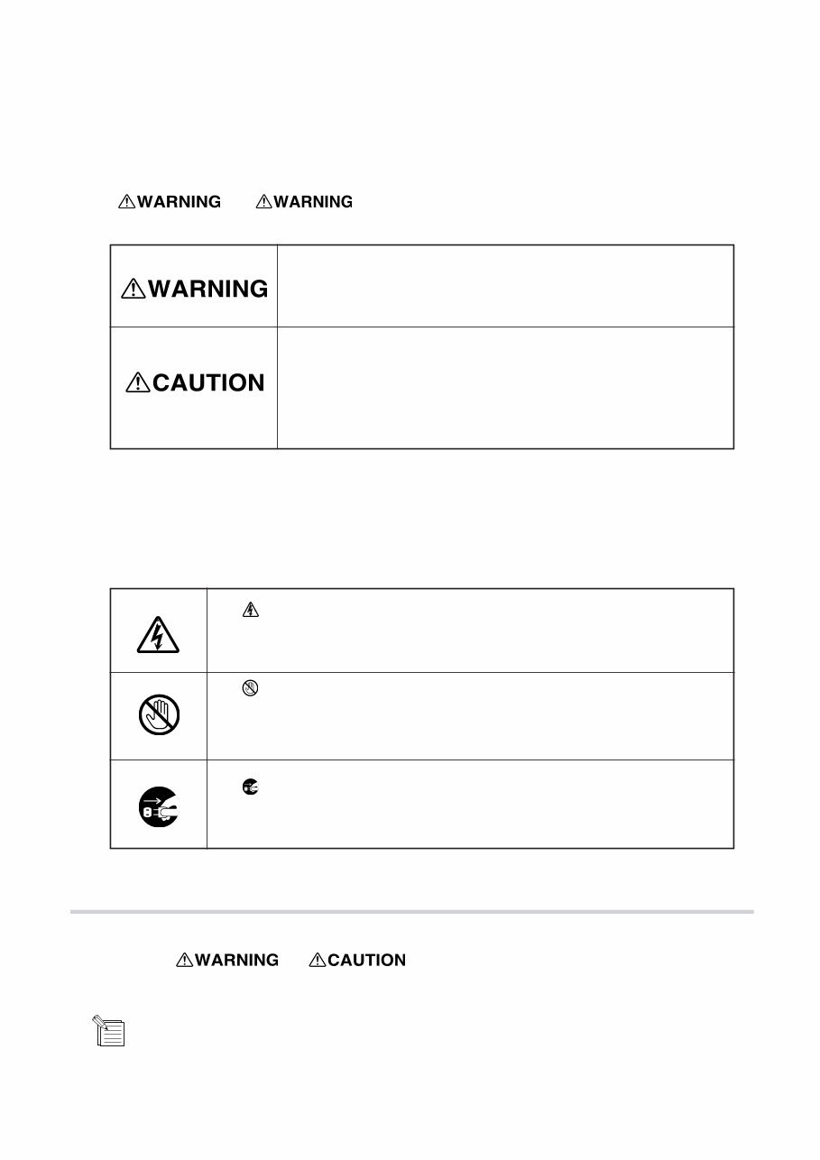
To Ensure Safe Work About and Notices. Used for instructions intended to alert the operator to the risk of death or severe injury should the unit be used improperly. Used for instructions intended to alert the operator to the risk of injury or material damage should the unit be used improperly. * material damage refers to damage or other adverse effects caused with respect to the home and all its furnishings, as well to domestic animals or pets. About the Symbols The symbol alerts the user to items that must never be carried out (are forbidden). The speci c thing that must not be done is indicated by the design contained within the circle. The symbol at left means not to touch. The symbol alerts the user to things that must be carried out. The speci c thing that must be done is indicated by the design contained within the circle. The symbol at left means the power-cord plug must be unplugged from the outlet. The symbol alerts the user to important instructions or warnings. The speci c meaning of the symbol is determined by the design contained within the triangle. The symbol at left means “danger of electrocution”. In addition to the and symbols, the symbols shown below are also used. : Tips and advise before the adjustment.
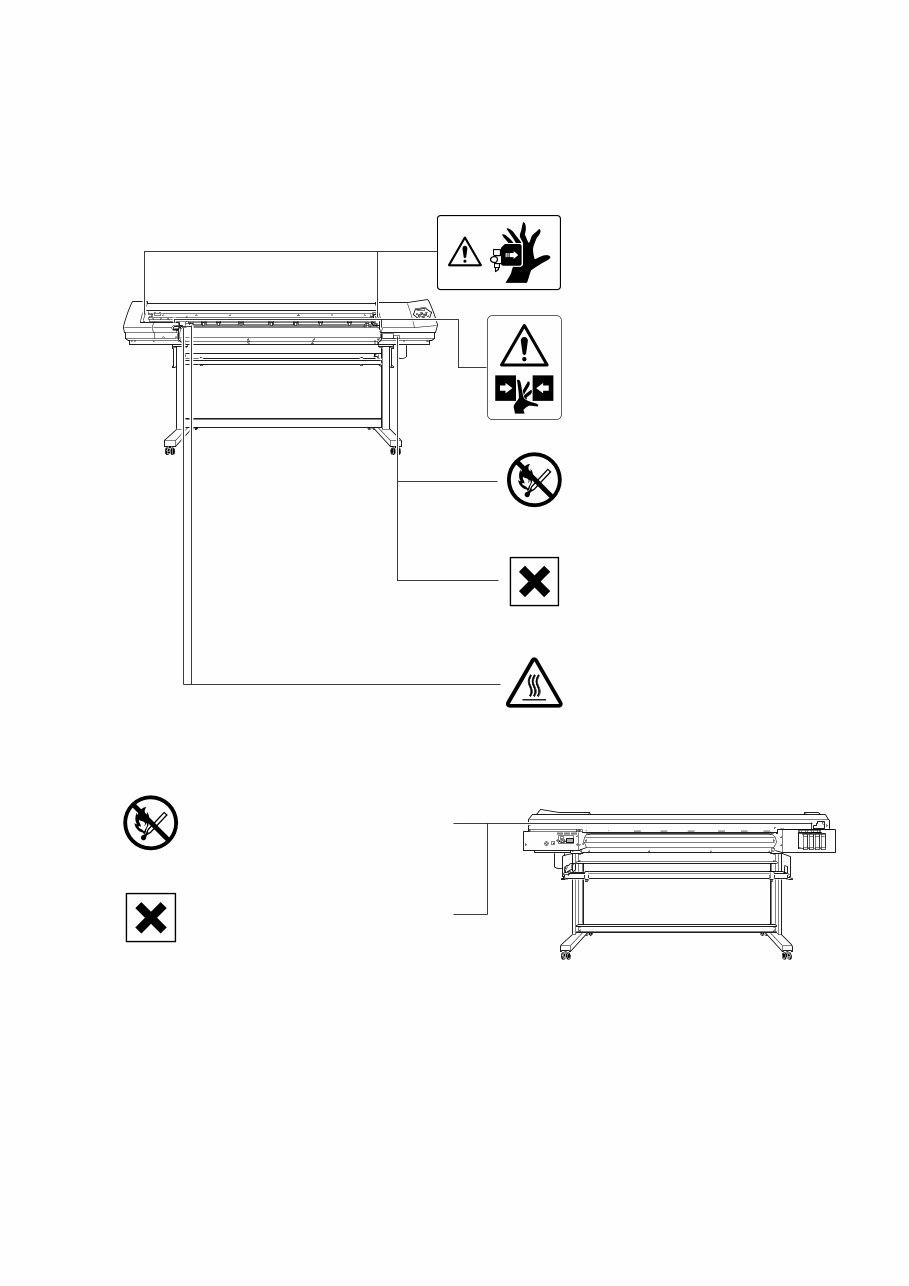
About the Labels Affixed to the Unit These labels are af xed to the body of this product. The following gure describes the location. Caution : Moving Print Heads The print heads move at high speed and pose a hazard. Caution : Pinching Hazard Contact during operation may cause the hand or ngers to become pinched, rsult- ing in injury. Caution : High Temperature The platen and dryer become hot. Exer- cise caution to avoid re or burns. Flammable Ink and discharged uid are ammable. Keep away from open ame. Ink Is Toxic Ink and discharged uid are toxic. Avoid contact with the body. Use only in a well- ventilated area. Flammable Ink and discharged uid are ammable. Keep away from open ame. Ink Is Toxic Ink and discharged uid are toxic. Avoid contact with the body. Use only in a well- ventilated area.
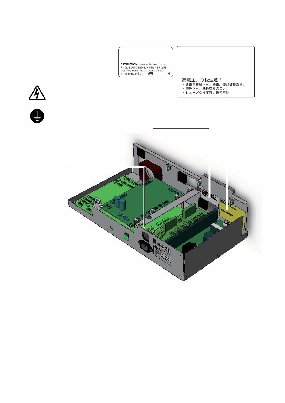
HIGH VOLTAGE, HANDLING ATTENTION • Do not touch during power on Electric shock, Compornents damage • Do not repair. Replace power unit. • Do not replace fuse. Can not be recovered. WARNING - FOR CONTINUED PROTECTION AGAINST RISK OF FIRE, REPLACE ONLY WITH FUSE OF THE SPECIFIED TYPE AND CURRENT RATING. F80L HS Electric charge. Do not touch when power is on. The wiring terminal untended for connec- tion of the protective earthing conductor associated with the supply wiring. Do not disconnect the cable of this termi- nal except the time of replacement.
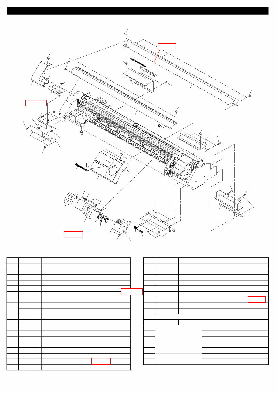
1 Structure & Spare Parts PARTS LIST -Main Parts- Parts No. Parts Name Parts No. Parts Name 1 W700461210 ASSY,PANEL BOARD VP-540 17 1000002637 SHEET,PANEL VP-540 2 23505834 CABLE-ASSY MAINT-COVER SW FJ-540 18 1000002625 STAY,PANEL VP-540 3 1000002608 COVER,INK CARTRIDGE VP-540 19 1000003029 SHEET,LCD VP-540 4 1000002633 COVER,CHASSIS VP-540 20 22535347 LABEL,CAUTION PINCH-2 #LA423 5 1000002620 COVER,MAINTENANCE VP-540 21 1000001099 LABEL,HARMFUL FIRE #LA915 1000002550 COVER,MAINTENANCE INKHEAD VP-540 22 22535441 LABEL,SET INK SP-300 #LA634 1000006236 COVER,MAINTENANCE INKHEAD 2 VP-540I 23 1000001620 LABEL,USE ECO-SOL MAX#LA924 1000002676 COVER,RAIL B VP-300 24 22535444 LABEL,READ MANUAL #LA637 1000002624 COVER,RAIL B VP-540 25 23475212 CABLE-CARD,24P1 600L BB 8 1000002651 COVER,RAIL B-RIGHT VP-540 PARTS LIST -Supplemental Parts- 1000002150 COVER,RAIL F VP-300 Parts No. Parts Name 1000002146 COVER,RAIL F VP-540 S1 31289111AS CUPSCREW SET, M4*6 NI 100 PCS. 10 1000002619 COVER,SIDE L VP-540 S2 31289109AS CUPSCREW SET,M3*4 NI 100 PCS. 11 1000002621 COVER,SIDE R VP-540 S3 31139103 PLAPOINT,FE4*6 WH 12 1000002627 COVER,UNDER L VP-540 S4 31149601 RING SET,PUSH-ON CS CSTW-3 100 PCS 13 1000002628 COVER,UNDER R VP-540 S5 31019149 SCREW SET,BINDING M2.3*8 3CBC 100PCS 14 22495102 KEY TOP,CLEAR GX-24 S6 31019703 SCREW,BINDING P-TIGHT M3*8 3C 100P 15 22495101 KEY TOP,WHITE GX-24 S7 31139104 SCREW,PLAPOINT M4*6 BK FE 16 1000002626 LABEL,EMBLEM LOGO VERSACAMM 1-1 COVER ( VP-540:Below ZW65382, VP-300:Below ZW61509 ) 1-1 7 9 6 13 4 8 9 3 7 10 5 6 12 16 11 17 18 1 2 14 15 14 19 22 20 20 21 23 21 24 25 S2 S2 S2 S1 S2 S2 S2 S2 S2 S2 S1 S2 S2 S2 S5 S3 S1 S1 S1 S7 S7 S1 S1 S1 S1 S6 S4 Revised 1 Revised 1 Revised7 Revised7 Revised 11 Revised 11
This comprehensive service manual provides detailed specifications, parts list, exploded views, and circuit board diagrams essential for repairing and servicing your Roland product. Whether you are a professional mechanic or a DIY enthusiast, this manual offers valuable insights for modifying, circuit bending, and fixing various features of your device. Additionally, it includes instructions to access the secret test mode in most products.
Featuring a detailed panel layout, circuit board layout, block diagram, disassembly procedure, LSI pin description, IC block diagram, and inspection guidelines, this manual equips you with the necessary information to bring your Roland product back to life. The MIDI implementation chart, overall circuit diagram, and high-resolution parts list further enhance the repair process.
With instant access after payment, you can conveniently begin your repairs without any shipping delays. The manual is available in format, ensuring high-quality printing for clear and precise instructions. It is compatible with various platforms including Windows, MAC, and Linux.
If you require service manuals for other Roland products, feel free to inquire. Thank you for choosing this official service and repair manual to maintain and restore your Roland device.
Reviews
Q&A
Recently Viewed
5,521,897Happy Clients
2,594,462eManuals
1,120,453Trusted Sellers
15Years in Business
Price:
Actual Price:
Roland vp540 vp-540 vp-300 vp300 complete service manual