
 Service Manual")

M199/M200/M203/M204
SERVICE MANUAL

It is the reader's responsibility when discussing the information contained
within this document to maintain a level of confidentiality that is in the best
interest of Ricoh Americas Corporation and its member companies.
NO PART OF THIS DOCUMENT MAY BE REPRODUCED IN ANY
FASHION AND DISTRIBUTED WITHOUT THE PRIOR
PERMISSION OF RICOH AMERICAS CORPORATION.
All product names, domain names or product illustrations, including
desktop images, used in this document are trademarks, registered
trademarks or the property of their respective companies.
They are used throughout this book in an informational or editorial fashion
only and for the benefit of such companies. No such use, or the use of
any trade name, or web site is intended to convey endorsement or other
affiliation with Ricoh products.
2014 RICOH Americas Corporation. All rights reserved.

The Service Manual contains information
regarding service techniques, procedures,
processes and spare parts of office equipment
distributed by Ricoh Americas Corporation.
Users of this manual should be either service
trained or certified by successfully completing a
Ricoh Technical Training Program.
Untrained and uncertified users utilizing
information contained in this service manual to
repair or modify Ricoh equipment risk personal
injury, damage to property or loss of warranty
protection.
Ricoh Americas Corporation
WARNING
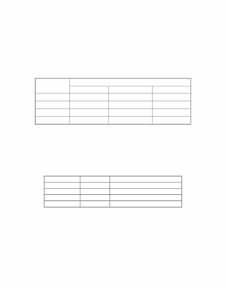
LEGEND
PRODUCT
CODE
COMPANY
LANIER RICOH SAVIN
M199 N/A SP C250DN N/A
M200 SP C252DN SP C252DN SP C252DN
M203 N/A SP C250SF N/A
M204 SP C250SF SP C250SF SP C250SF
DOCUMENTATION HISTORY
REV. NO. DATE COMMENTS
* 04/2014 Original Printing

SM i M199/M200/M203/M204
M199/M200/M203/M204
TABLE OF CONTENTS
1. PRODUCT INFORMATION ........................................................... 1-1
1.1 MACHINE OVERVIEW .............................................................................. 1-1
1.1.1 COMPONENT LAYOUT ................................................................... 1-1
Engine (M199/M200) ............................................................................ 1-1
Engine (M203/M204) ............................................................................ 1-2
ADF (only for M203/M204) ................................................................... 1-3
Scanner (only for M203/M204) ............................................................. 1-3
1.1.2 PAPER PATH ................................................................................... 1-4
ADF (only for M203/M204) ................................................................... 1-4
1.1.3 DRIVE LAYOUT ............................................................................... 1-5
1.2 MACHINE CONFIGURATION ................................................................... 1-7
1.2.1 PRINTER MODEL (M199/M200) ...................................................... 1-7
1.2.2 MF MODEL (M203/M204)................................................................. 1-7
1.3 GUIDANCE FOR THOSE WHO ARE FAMILIAR WITH PREDECESSOR
PRODUCTS ..................................................................................................... 1-8
1.3.1 PRINTER MODELS: ......................................................................... 1-8
1.3.2 MF MODELS: ................................................................................... 1-8
2. INSTALLATION ............................................................................. 2-1
2.1 INSTALLATION REQUIREMENTS ............................................................ 2-1
2.1.1 ENVIRONMENT ............................................................................... 2-1
2.1.2 MACHINE LEVEL ............................................................................. 2-1
2.1.3 MACHINE SPACE REQUIREMENTS .............................................. 2-2
Printer Models (M199/M200) ................................................................ 2-2
MF Models (M203/M204) ..................................................................... 2-3
2.1.4 POWER REQUIREMENTS .............................................................. 2-3
2.1.5 INSTALLATION PROCEDURE ........................................................ 2-3
3. REPLACEMENT AND ADJUSTMENT ......................................... 3-1
3.1 BEFORE YOU START ............................................................................... 3-1
3.1.1 GENERAL PRECAUTIONS .............................................................. 3-1
AIO ....................................................................................................... 3-1
Laser Unit ............................................................................................. 3-2
Transfer Roller ..................................................................................... 3-2
Fusing .................................................................................................. 3-2

M199/M200/M203/M204 ii SM
Paper Feed .......................................................................................... 3-2
Scanner Unit (for M203/M204) ............................................................. 3-3
3.1.2 RELEASING PLASTIC LATCHES .................................................... 3-3
3.1.3 AFTER SERVICING THE MACHINE ................................................ 3-4
3.1.4 LITHIUM BATTERIES (MF MODELS) .............................................. 3-4
3.2 SPECIAL TOOLS....................................................................................... 3-5
3.3 EXTERIOR COVERS ................................................................................ 3-6
3.3.1 REAR COVER .................................................................................. 3-6
Rear Cover (Printer Models) ................................................................ 3-6
Rear Cover (MF Models) ...................................................................... 3-7
3.3.2 RIGHT COVER ................................................................................. 3-8
3.3.3 LEFT COVER ................................................................................... 3-8
Printer Models ...................................................................................... 3-8
MF Models ........................................................................................... 3-9
3.3.4 FRONT COVER UNIT .................................................................... 3-10
3.4 SCANNER UNIT (ONLY FOR MF MODELS) .......................................... 3-11
3.4.1 SCANNER UNIT ............................................................................. 3-11
3.5 ADF (ONLY FOR MF MODELS) .............................................................. 3-14
3.5.1 ADF UNIT ....................................................................................... 3-14
3.5.2 ORIGINAL TRAY ............................................................................ 3-14
3.5.3 ADF PICK-UP ROLLER .................................................................. 3-15
3.5.4 ADF FEED ROLLER ....................................................................... 3-16
3.5.5 ADF SEPARATION PAD ................................................................ 3-16
3.5.6 ADF FRONT COVER...................................................................... 3-17
3.5.7 ADF REAR COVER ........................................................................ 3-18
3.5.8 ADF MOTOR .................................................................................. 3-19
3.5.9 ADF TOP COVER........................................................................... 3-20
3.5.10 DOCUMENT SENSOR ............................................................. 3-21
3.5.11 ADF FEED SENSOR ................................................................ 3-23
3.6 LASER UNIT ............................................................................................ 3-24
3.6.1 CAUTION DECAL LOCATIONS ..................................................... 3-24
3.6.2 LASER OPTICS HOUSING UNIT ................................................... 3-25
Printer Models .................................................................................... 3-25
MF Models ......................................................................................... 3-26
After replacing the laser optics housing unit ....................................... 3-28
Printing out the test chart to make sure MUSIC was performed correctly
........................................................................................................... 3-29
Checking that MUSIC was Performed Correctly ................................ 3-30
If MUSIC has not been performed successfully ................................. 3-31

SM iii M199/M200/M203/M204
3.7 AIO CARTRIDGE (ALL IN ONE CARTRIDGE)........................................ 3-32
3.7.1 AIO CARTRIDGE............................................................................ 3-32
3.7.2 BLACK AIO MOTOR....................................................................... 3-32
3.7.3 COLOR AIO MOTOR...................................................................... 3-35
3.8 IMAGE TRANSFER ................................................................................. 3-37
3.8.1 IMAGE TRANSFER BELT UNIT ..................................................... 3-37
After replacing the image transfer belt unit ......................................... 3-38
3.8.2 ITB (IMAGE TRANSFER BELT) CLEANING UNIT ........................ 3-38
3.8.3 AGITATOR MOTOR ....................................................................... 3-39
3.8.4 ITB (IMAGE TRANSFER BELT) CONTACT MOTOR..................... 3-40
3.8.5 ITB (IMAGE TRANSFER BELT) CONTACT SENSOR ................... 3-42
3.8.6 TM (TONER MARK) SENSOR BASE ............................................. 3-43
3.8.7 WASTE TONER BOTTLE SET SENSOR....................................... 3-44
3.8.8 WASTE TONER OVERFLOW SENSOR ........................................ 3-45
3.9 PAPER TRANSFER ................................................................................ 3-46
3.9.1 TRANSFER UNIT ........................................................................... 3-46
3.9.2 TRANSFER ROLLER ..................................................................... 3-47
3.9.3 REGISTRATION ROLLER.............................................................. 3-48
Reassembling the registration roller unit ............................................ 3-49
3.9.4 REGISTRATION SENSOR ............................................................. 3-49
3.9.5 REGISTRATION CLUTCH ............................................................. 3-50
3.10 IMAGE FUSING ................................................................................. 3-51
3.10.1 FUSING UNIT ........................................................................... 3-51
3.10.2 FUSING LAMP .......................................................................... 3-53
When Reinstalling the Fusing Lamp ................................................... 3-55
When Reassembling the Fusing Unit ................................................. 3-56
3.10.3 TRANSPORT/FUSING MOTOR ............................................... 3-56
3.11 PAPER FEED .................................................................................... 3-58
3.11.1 PAPER FEED CLUTCH ............................................................ 3-58
3.11.2 PAPER FEED ROLLER ............................................................ 3-58
3.11.3 SEPARATION PAD ................................................................... 3-59
3.11.4 PAPER END SENSOR ............................................................. 3-60
3.12 PAPER EXIT ...................................................................................... 3-61
3.12.1 PAPER EXIT ROLLER .............................................................. 3-61
3.12.2 PAPER EXIT SENSOR ............................................................. 3-62
3.13 ELECTRICAL COMPONENTS .......................................................... 3-63
3.13.1 CONTROLLER BOARD ............................................................ 3-63
Controller Board (Printer Models) ....................................................... 3-63
Controller Board (MF Models) ............................................................ 3-64

M199/M200/M203/M204 iv SM
3.13.2 EGB (ENGINE BOARD) ............................................................ 3-66
EGB (Printer Models) ......................................................................... 3-66
EGB (MF Models)............................................................................... 3-67
3.13.3 FCU (ONLY FOR MF MODELS) ............................................... 3-69
3.13.4 OPERATION PANEL ................................................................ 3-69
Printer Models .................................................................................... 3-70
MF Models ......................................................................................... 3-70
Printer Models .................................................................................... 3-71
MF Models ......................................................................................... 3-71
3.13.5 OPU .......................................................................................... 3-71
OPU (Printer Models) ......................................................................... 3-71
OPU (MF Models) .............................................................................. 3-72
3.13.6 WI-FI BOARD............................................................................ 3-73
3.13.7 INTERLOCK SWITCHES .......................................................... 3-74
3.13.8 FUSING FAN MOTOR .............................................................. 3-75
3.13.9 FUSING STRIPPER PAWL SOLENOID ................................... 3-76
3.13.10 FUSING PRESSURE RELEASE SENSOR ........................... 3-77
3.13.11 LSU FAN MOTOR ................................................................. 3-78
3.13.12 ID CHIP BOARD .................................................................... 3-78
3.13.13 PSU ....................................................................................... 3-79
3.13.14 HIGH VOLTAGE POWER SUPPLY BOARD ........................ 3-81
3.13.15 TEMPERATURE/HUMIDITY SENSOR ................................. 3-81
3.13.16 DUPLEX MOTOR .................................................................. 3-82
3.13.17 SPEAKER (ONLY FOR MF MODELS) .................................. 3-84
3.13.18 EEPROM ............................................................................... 3-85
Checking that MUSIC was Performed Correctly ................................ 3-87
4. SYSTEM MAINTENANCE REFERENCE ..................................... 4-1
4.1 SERVICE MENU........................................................................................ 4-1
4.1.1 OVERVIEW ...................................................................................... 4-1
Menu Mode .......................................................................................... 4-1
Special Mode ....................................................................................... 4-1
4.1.2 MAINTENANCE MODE MENU (MF MODELS) ................................ 4-2
Menu List.............................................................................................. 4-2
4.1.3 SERVICE MODE (PRINTER MODELS) ......................................... 4-14
Menu List............................................................................................ 4-14
4.1.4 FAX SERVICE TEST MENU (ONLY FOR MF MODELS) ............... 4-18
Entering the Fax Service Test Menu .................................................. 4-18
Selecting an Item................................................................................ 4-18
Going into the Next Level/ Returning to the Previous Level ............... 4-18

SM v M199/M200/M203/M204
Exiting the Maintenance Mode Menu ................................................. 4-18
Menu List............................................................................................ 4-18
4.1.5 SIZE MISMATCH DETECTION MENU........................................... 4-20
Entering the Size Mismatch Detection Menu...................................... 4-20
4.2 CONFIGURATION, MAINTENANCE AND TEST PAGE INFORMATION 4-21
4.2.1 OVERVIEW .................................................................................... 4-21
To Print the Configuration Page/ Test Page/ Maintenance Page (Printer
Models) .............................................................................................. 4-21
To Print the Configuration Page/ Maintenance Page (MF Models) .... 4-21
4.2.2 ERROR LOG .................................................................................. 4-22
4.2.3 COUNTER AND COVERAGE (ONLY FOR PRINTER MODELS) .. 4-23
Configuration Page............................................................................. 4-23
4.3 FIRMWARE UPDATING .......................................................................... 4-24
4.3.1 CHECKING THE MACHINE FIRMWARE VERSION ...................... 4-24
To Print the Configuration Page (Printer Models)............................... 4-24
To Print the Configuration Page (MF Models) .................................... 4-24
4.3.2 UPDATING THE CONTROLLER FIRMWARE ............................... 4-25
Procedure........................................................................................... 4-25
4.3.3 UPDATING THE ENGINE FIRMWARE .......................................... 4-28
4.3.4 BOOT LOADER FIRMWARE ......................................................... 4-30
5. TROUBLESHOOTING................................................................... 5-1
5.1 SERVICE CALL CONDITIONS .................................................................. 5-1
5.1.1 SUMMARY ....................................................................................... 5-1
5.1.2 ENGINE SC ...................................................................................... 5-1
SC 1xx (Other Error) ............................................................................ 5-1
SC 2xx (Laser Optics Error) ................................................................. 5-2
SC 3xx (Charge Error).......................................................................... 5-3
SC 4xx (Image Transfer and Transfer Error) ........................................ 5-4
SC 5xx (Motor and Fusing Error).......................................................... 5-5
SC 6xx (Communication and Other Error).......................................... 5-10
5.1.3 CONTROLLER SC ......................................................................... 5-11
SC8xx................................................................................................. 5-11
5.2 ERROR CODES ...................................................................................... 5-12
5.2.1 OVERVIEW .................................................................................... 5-12
5.2.2 ERROR CODES LIST..................................................................... 5-12
5.3 FAX ERROR CODE DEFINITION (ONLY FOR MF MODELS) ................ 5-16
5.3.1 BASIC ERROR CODE STRUCTURE ............................................. 5-16
Digit 5 (far left): TX or RX ................................................................... 5-16
Digit 4: Coding (MH/MR/MMR/JBIG) .................................................. 5-16

M199/M200/M203/M204 vi SM
Digit 3: Modem mode ......................................................................... 5-17
Digit 2: Modem speed ........................................................................ 5-18
5.3.2 ERROR CODE TABLE ................................................................... 5-19
The following information is also included in the User Guide. ............ 5-21
5.4 FAX ERROR CLEAR PRINCIPLE (ONLY FOR MF MODELS) ............... 5-25
5.4.1 RX ................................................................................................... 5-25
5.4.2 TX ................................................................................................... 5-25
5.5 IMAGE PROBLEMS ................................................................................ 5-26
5.5.1 OVERVIEW .................................................................................... 5-26
5.5.2 IMAGE PROBLEM .......................................................................... 5-27
6. ENVIRONMENTAL CONSERVATION ......................................... 6-1
6.1 ENERGY SAVING ..................................................................................... 6-1
6.1.1 ENERGY SAVER MODES ............................................................... 6-1
Timer Settings (Printer Models)............................................................ 6-2
Timer Settings (MF Models) ................................................................. 6-2
Return to Stand-by Mode ..................................................................... 6-2
Recommendation ................................................................................. 6-3
6.2 PAPER SAVE ............................................................................................ 6-4
6.2.1 EFFECTIVENESS OF DUPLEX/COMBINE FUNCTION .................. 6-4
1. Duplex .............................................................................................. 6-4
2. Combine mode ................................................................................. 6-4
3. Duplex + Combine............................................................................ 6-5
You're Reading a Preview
What's Included?
Fast Download Speeds
Online & Offline Access
Access PDF Contents & Bookmarks
Full Search Facility
Print one or all pages of your manual
$33.99
Ricoh SPC250DN, SPC252DN, SPC250SF, SPC250SF (product code M199 M200 M203 M204) Service Manual
Viewed 57 Times Today

What's Included?
Fast Download Speeds
Online & Offline Access
Access PDF Contents & Bookmarks
Full Search Facility
Print one or all pages of your manual
$33.99

Secure transaction
What's Included?
Fast Download Speeds
Online & Offline Access
Access PDF Contents & Bookmarks
Full Search Facility
Print one or all pages of your manual
Description
Get the detailed Service Manual for Ricoh SPC250DN, SPC252DN, SPC250SF, SPC250SF copiers. This manual contains comprehensive diagrams, pictures, and procedures for diagnosing and repairing your copier. It is a valuable resource for both professional mechanics and DIY enthusiasts.
The manual includes:
- Product Information
- Machine Overview
- Machine Configuration
- Guidance for Those Who Are Familiar with Predecessor Products
- Installation
- Installation Requirements
- Power Requirements
- Installation Procedure
- Replacement and Adjustment
- Before You Start
- Special Tools
- Exterior Covers
- Scanner Unit (Only for MF Models)
- ADF (Only for MF Models)
- Laser Unit
- System Maintenance Reference
- Service Menu
- Configuration, Maintenance and Test Page Information
- Firmware Updating
- Troubleshooting
- Service Call Conditions
- Error Codes
- Fax Error Code Definition (Only for MF Models)
- Fax Error Clear Principle (Only for MF Models)
- Image Problems
- Environmental Conservation
- Energy Saving
- Paper Save
This manual is in PDF format and is 218 pages long. It provides essential information for maintaining and repairing Ricoh SPC250DN, SPC252DN, SPC250SF, SPC250SF copiers.


