Oki Data CONFIDENTIAL 1 2 3 4 5 6 Rev Date DCO No. Contents Design Approval BOM Use for Certification Body Approval Check Date Drawing No. Name Design ..................................................................................................... ..................................................................................................... C5450/C5400/C5250/C5200/C5150/ C3200n/C3200/C3100 Color LED Page Printer Maintenance Manual ODA/OEL/INT [Rev. 6] No.01 42615101TH C5450/C5400/C5250/C5200/C5150/ C3200n/C3200/C3100 Maintenance Manual 1 249 2004-03-12 Yujiro Iida Sakae Ogashiwa 5 2004-10-29 SP7-2346 Change considerably Hideki Enomoto Hideki Enomoto 6 2005-03-02 SP7-2611 Add C5450/C5250/C3200 Hideki Enomoto Hideki Enomoto
42615101TH Rev.6 2 / Oki Data CONFIDENTIAL 1 2004-03-12 ISSUE MD11 Ogashiwa 5 2004-10-29 Total pages Change considerably ME3 H. Enomoto 6 2005-03-02 Add C5450/C5250/C3200. ME3 H. Enomoto Rev.No. Date No. Corrected items Page Description of change Person in charge Document Revision History
42615101TH Rev.6 3 / Oki Data CONFIDENTIAL PREFACE This manual describes the procedures of the maintenance of the C5450/C5400/C5250/C5200/C5150/ C3200n/C3200/C3100 printers. The document is produced for maintenance personnel use. For details on the procedures for handling the C5450/C5400/C5250/C5200/C5150/C3200n/C3200/C3100 of printers, see its user documentation. Note! • The descriptions in this manual are subject to change without prior notice. • In preparing the document, efforts have been made to ensure that the information in it is accurate. However, errors may be crept into the document. Oki Data assumes no responsibility for any damage resulting from, or claimed to be the results of, those repairs, adjustments or modifica- tions to the printers which are made by users using the manual. • The parts used for the printers are sensitive and, if handled improperly, may be damaged. It is strongly recommended that the products are maintained by maintenance men registered with Oki Data. • Remove static electricity before working.
42615101TH Rev.6 4 / Oki Data CONFIDENTIAL 1. SPECIFICATIONS ............................................................................................... 7 1.1 System Configuration ........................................................................................................... 7 1.2 Printer Configuration .......................................................................................................... 10 1.3 Option Configuration .......................................................................................................... 13 1.4 Specifications ..................................................................................................................... 14 1.5 INTERFACE SPECIFICATIONS ........................................................................................ 18 1.5.1 Parallel Interface Specifications (C5450/C5400) .................................................. 18 1.5.1.1 Parallel Interface ................................................................................... 18 1.5.1.2 Parallel Interface Connector and Cable ................................................ 18 1.5.1.3 Parallel Interface Level .......................................................................... 18 1.5.1.4 Timing Charts ........................................................................................ 19 1.5.1.5 Parallel I/F Signals ................................................................................ 20 1.5.2 Universal Serial Bus (USB) Interface Specifications(C5450/C5400/C5250/ C5200/C5150/C3200n/C3200/C3100) ................................................................... 21 1.5.2.1 USB Interface ........................................................................................ 21 1.5.2.2 USB Interface Connector and Cable ..................................................... 21 1.5.2.3 USB Interface Signals ........................................................................... 21 1.5.3 Network Interface Specifications(C5450/C5400/C5250/C5200/C5150/C3200n) . 22 1.5.3.1 Network Interface .................................................................................. 22 1.5.3.2 Network Interface Connector and Cable ............................................... 22 1.5.3.3 Network Interface Signals ..................................................................... 22 2. OPERATION DESCRIPTION ............................................................................ 23 2.1 Electrophotographic Process Mechanism .......................................................................... 23 2.2 Printing Processes ................................................................................................................ 28 3. PRINTER INSTALLATION ................................................................................. 38 3.1 Precautions and Prohibition .................................................................................................. 38 3.2 Printer Unpacking Procedure ................................................................................................ 40 3.3 Printer Installation Instructions .............................................................................................. 41 3.4 Packed Units and Attachments ............................................................................................. 42 3.5 Assembly Procedure ............................................................................................................. 43 3.5.1 Printer Main Body .................................................................................................... 43 3.5.2 Power Cable Connection ......................................................................................... 48 3.5.3 Installation of Optional Components ........................................................................ 51 3.5.4 Checking of Optional-Component Recognition ........................................................ 60 3.6 MenuMap Printing ................................................................................................................. 61 3.7 Connection Procedures ........................................................................................................ 64 3.8 Checking of User Paper ........................................................................................................ 66 4. PARTS REPLACEMENT ................................................................................... 67 4.1 Precautions in Replacing Parts .......................................................................................... 67 4.2 Part Replacement Procedures ........................................................................................... 69 4.2.1 Left Side Cover ..................................................................................................... 69 4.2.2 Right Side Cover .................................................................................................. 70 4.2.3 Face-Up Tray ........................................................................................................ 71 4.2.4 Rear Cover ........................................................................................................... 72 4.2.5 LED Assy / LED Assy-Springs .............................................................................. 73 4.2.6 Controller PCB ...................................................................................................... 74 4.2.7 Print Engine Controller PCB ................................................................................. 76 4.2.8 Top Cover Assy .................................................................................................... 79 4.2.9 Top Cover ............................................................................................................. 80 4.2.10 Controller Panel Assy ........................................................................................... 81 4.2.11 Board-PRP(C5450/C5400/C5250/C5200/C5150/C3200n)/ Board-PRO(C3200/C3100) / Top Cover Handle ................................................. 82 CONTENTS
42615101TH Rev.6 5 / Oki Data CONFIDENTIAL 4.2.12 Low-Voltage Power Unit / ID-FAN / Low-Voltage Power Unit FAN / Hopping Motor / Fuser Motor ................................................................................ 83 4.2.13 Board-PRT ............................................................................................................ 84 4.2.14 Guide-Eject Assy / Color Registration Assy / Board-PRM .................................... 85 4.2.15 FAN (Fuser) / Belt Motor / High Voltage Power Supply Board / Cover Open Switch 87 4.2.16 MPT-Assy ............................................................................................................. 88 4.2.17 Feeder Unit / Board-RSF / MPT Hopping Roller / Frame Assy Separator / Cover-Front .......................................................................................................... 89 4.2.18 Main Motors / Solenoid / Paper-End Sensor ........................................................ 90 4.2.19 Feed Roller ........................................................................................................... 92 4.2.20 Shaft Assy-Eject (FU) / Shaft Assy-Eject (FD) / Eject Sensor .............................. 93 4.2.21 Fuser Unit ............................................................................................................. 94 4.2.22 Belt Unit ................................................................................................................ 95 4.3 Parts to lubricate ................................................................................................................ 96 5. MAINTENANCE MENU ................................................................................... 111 5.1 System Maintenance Menu(For Maintenance Staff) ........................................................ 111 5.2 Maintenance Utility ........................................................................................................... 114 5.3 Changing the display language ........................................................................................ 118 5.4 Maintenance Menu Function of the User Menu ............................................................... 119 5.4.1 Maintenance Menu(For End-Users) ................................................................... 119 5.4.2 Self-diagnostic Mode .......................................................................................... 120 5.4.2.1 Operator panel .................................................................................... 120 5.4.2.2 Normal self-diagnostic mode (level 1) ................................................. 124 5.4.2.2.1 Entering self-diagnostic mode (level 1) ............................... 126 5.4.2.2.2 Exiting self-diagnostic mode ............................................... 126 5.4.2.3 Switch scan test .................................................................................. 127 5.4.2.4 Motor and clutch test ........................................................................... 130 5.4.2.5 Test printing ........................................................................................ 132 5.4.2.6 Color registration adjustment test ....................................................... 137 5.4.2.7 Print density adjustment test ............................................................... 137 5.4.2.8 Consumable counter display ............................................................... 138 5.4.2.9 Counter display of numbers of prints and images ............................... 138 5.4.2.10 Switching between Factory and Shipping modes ............................... 139 5.4.2.11 Self-diagnosis function setting ............................................................ 140 5.4.2.12 Waste toner counter display ................................................................ 141 5.4.2.13 LED head serial number display ......................................................... 141 5.4.2.14 Operator panel display ........................................................................ 142 5.4.3 Printing on Controller-Equipped Printer on a Standalone Basis ......................... 147 5.4.4 Switch Press Functions at Printer Power-On ..................................................... 148 5.5 Settings after Parts Replacement .................................................................................... 149 5.5.1 Instructions to exchange the engine control board ............................................. 149 5.5.2 EEPROM Setting after ARC Board/SPY Board/SPA Board Replacement ........ 152 5.5.3 Destination Setting [Check Method: Printing demo page (C5450, C5400), Printing Menu Map (C5250, C5200, C5150, C3200n, C3200, C3100)] ............. 153 5.6 Settings by Hand for Print Density Adjustment ................................................................ 155 6. REGULAR MAINTENANCE ............................................................................ 156 6.1 Parts Replaced Regularly ................................................................................................ 156 6.2 Cleaning ........................................................................................................................... 156 6.3 Cleaning the LED Lens Array .......................................................................................... 156 6.4 Cleaning the Pick-up Roller and the Pad ......................................................................... 158 6.5 Cleaning the Printer Inside ............................................................................................... 159 7. TROUBLESHOOTING PROCEDURES .......................................................... 161 7.1 Precautions before troubleshooting ................................................................................. 161 7.2 Precautions before handling an abnormal image ............................................................ 161
42615101TH Rev.6 6 / Oki Data CONFIDENTIAL 7.3 Precautions upon handling an abnormal image ............................................................... 161 7.4 Preparing for Troubleshooting ......................................................................................... 161 7.5 Troubleshooting Procedure .............................................................................................. 161 7.5.1 LCD message list ............................................................................................... 162 7.5.2 Preparing for troubleshooting ............................................................................. 174 7.5.2.(1)LCD Display Malfunction ................................................................................. 176 7.5.2.(2)Irregular Operation of the device after turning on the power ........................... 179 7.5.2.(3)Paper Feed Jam(Error 391:1st Tray) ............................................................... 189 7.5.2.(4)Paper Feed Jam (Error 390:Multi-purpose Tray) ............................................. 191 7.5.2.(5)Paper Path Jam(Error 381) ............................................................................. 193 7.5.2.(6)Paper Exit Jam(Error 382) ............................................................................... 198 7.5.2.(7)Duplex Print Jam(Error 370,371,372,373,383) ............................................... 201 7.5.2.(8)Paper Size Error (Error 400) ........................................................................... 203 7.5.2.(9)ID Unit Up-Down Error(Service Call 140-143) ................................................. 204 7.5.2.(10)Fuser Unit Error(Error 170-177) .................................................................... 205 7.5.2.(11)Motor Fan Error(Error 120,127,051) .............................................................. 206 7.5.2.(12)Print Speed is Slow (Low Performance) ........................................................ 207 7.5.2.(13)Option unit is not recognized ......................................................................... 207 7.5.2.(14)LED head is not recognized(Error 131,132,133,134) .................................... 208 7.5.2.(15)Toner cartridge is not recognized(Error 540,541,542,543) ............................ 209 7.5.2.(16)Fuse Cutout Error (Error 150-155) ................................................................ 213 7.5.2.(17)Dew Condensation Errors (Error 123) ........................................................... 213 7.5.3 Image Problem Troubleshooting ........................................................................ 214 7.5.3.(1)Color is totally pale (Fig.7.2 A ) ........................................................................ 215 7.5.3.(2)Background is dirty (Fig.7.2 B ) ....................................................................... 216 7.5.3.(3)Blank Print (Fig.7.2 C ) .................................................................................... 217 7.5.3.(4)Vertical lines are printed .................................................................................. 218 7.5.3.(5)Cyclic Print Trouble (Refer to Fig.7.2 E ) ......................................................... 219 7.5.3.(6)Color drift is wide. ............................................................................................ 220 7.5.3.(7)Solid Black Print .............................................................................................. 221 7.5.4 Actions Taken after Forced HDD/Flash Initialization .......................................... 222 7.5.5 Network Troubleshooting .................................................................................... 223 7.5.6 Displaying Details of Service Call Error Codes (C3200/C3100) ......................... 224 7.6 Fuse Checking ................................................................................................................. 225 8. CONNECTION DIAGRAM ............................................................................... 226 8.1 Resistance Checks .......................................................................................................... 226 8.2 PCB Parts Layouts ........................................................................................................... 230
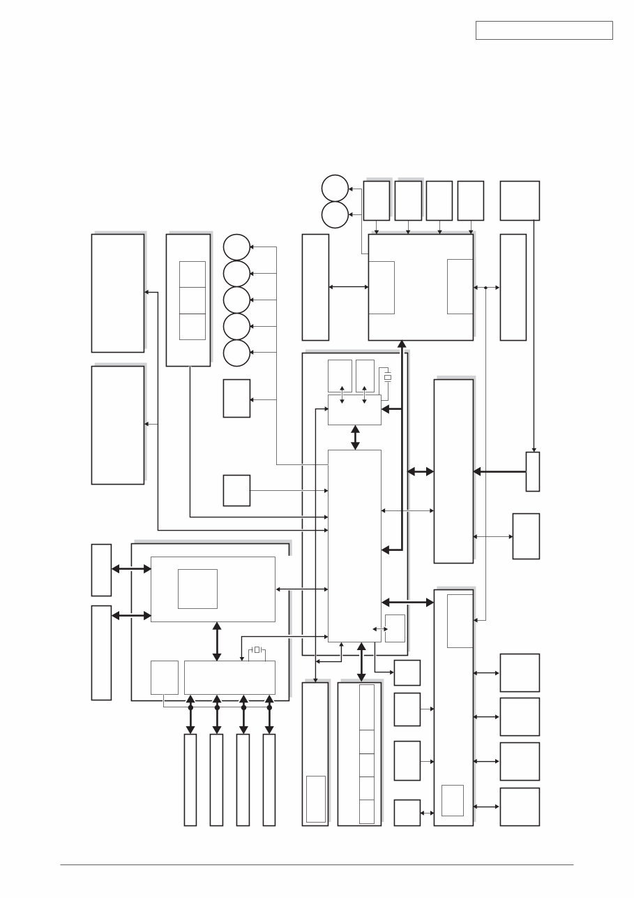
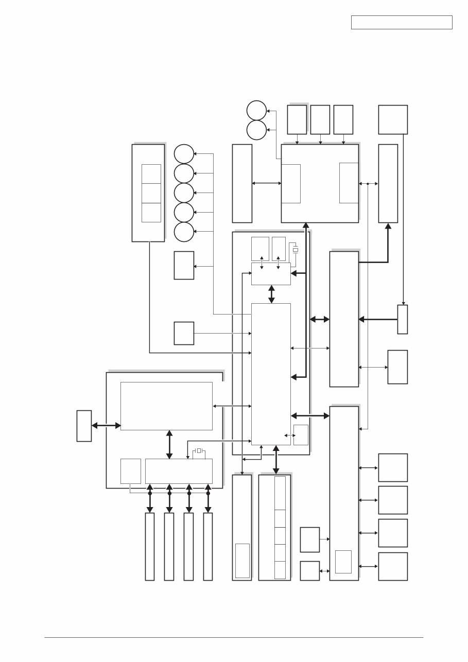
42615101TH Rev.6 7 / Oki Data CONFIDENTIAL K LED HEAD Y LED HEAD M LED HEAD C LED HEAD Environment Sensor Operator Panel Board Toner Sensor Board High Voltage Board Low Voltage Board MCON CPU Paperfeed Solenoid M KID Front Sensor Board Duplex Board 2nd Tray Board IN1 IN2 WR M YID M MID M CID M HOP 1st P.E Sensor Belt Unit PU-Board Driver Relay Board Fuser Inlet EXIT Sensor Density Sensor Color Registration Board-Right Color Registration Board-Left M BELT M HEAT Belt Unit Fuse Cut-Out Fuser Fuse Cut-Out/ Up & Low/ Thermistor Fuse Cut-Out, Exit, Motor Control Color Registration, Density, Thermistor Signals Environment Temperature Humidity Signals 28MHz FLASH 8M bit SRAM 256Kbit High Voltage Interface, Fan Control, Cover-Open Fan, Heater Control, etc 3.3V, 5V, 24V, 0VL, 0VP EEPROM K-ID Y-ID M-ID C-ID Low-Voltage FAN AC-SW Fusing FAN ID FAN Belt Thermistor Heater Frame Thermistor ID UP/ Down Cover- Open Sensor K toner sensor Y toner sensor M toner sensor C toner sensor Image drum fuse cut-out DCON 50MHz Video Interface (data8bit × 4, fsync × 4, Isync, wclk) LVDS Driver LAN, USB, Centro I/F HDD CU Board CU-FAN CU Area DCON I/F, LSYNC Command Interface 1. SPECIFICATIONS 1.1 System Configuration C5450/C5400 Figure 1-1-1 shows the system configuration of C5450/C5400. Figure 1-1-1
42615101TH Rev.6 8 / Oki Data CONFIDENTIAL C5250/C5200/C5150/C3200n Figure 1-1-2 shows the system configuration of C5250/C5200/C5150/C3200n. Figure 1-1-2 K LED HEAD Y LED HEAD M LED HEAD C LED HEAD ASIC (ARBOKS) 33MHz Video Interface (data8bit × 4, fsync × 4, Isync, wclk) USB I/F LAN I/F CU Board CPU CU Area DCON I/F, LSYNC Environment Sensor Operator Panel Board Toner Sensor Board High Voltage Board Low Voltage Board MCON CPU Paperfeed Solenoid M KID Front Sensor Board Duplex Board 2nd Tray Board IN1 IN2 WR M YID M MID M CID M HOP 1st P.E Sensor Belt Unit PU-Board Driver Relay Board Fuser Inlet EXIT Sensor Density Sensor Color Registration Board-Right Color Registration Board-Left M BELT M HEAT Belt Unit Fuse Cut-Out Fuser Fuse Cut-Out/ Up & Low/ Thermistor Fuse Cut-Out, Exit, Motor Control Color Registration, Density, Thermistor Signals Environment Temperature Humidity Signals 28MHz FLASH 8M bit SRAM 256Kbit High Voltage Interface, Fan Control, Cover-Open Fan, Heater Control, etc 3.3V, 5V, 24V, 0VL, 0VP EEPROM K-ID Y-ID M-ID C-ID Low-Voltage FAN AC-SW Fusing FAN ID FAN Belt Thermistor Heater Frame Thermistor ID UP/ Down Cover- Open Sensor K toner sensor Y toner sensor M toner sensor C toner sensor Image drum fuse cut-out * Except C3200n
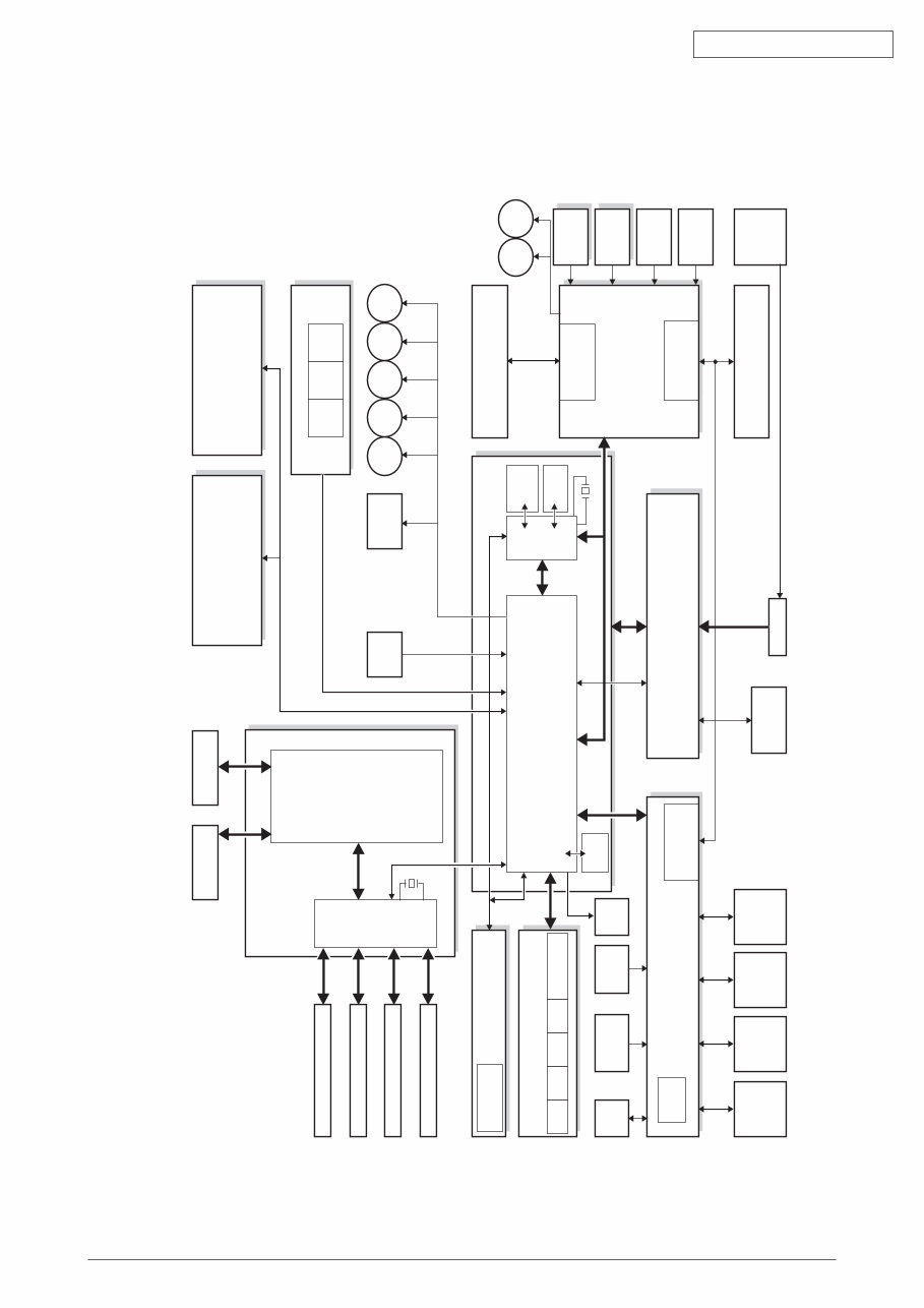
42615101TH Rev.6 9 / Oki Data CONFIDENTIAL C3200/C3100 Figure 1-1-3 shows the system configuration of C3200/C3100. Figure 1-1-3 K LED HEAD Y LED HEAD M LED HEAD C LED HEAD Environment Sensor Operator Panel Board Toner Sensor Board High Voltage Board Low Voltage Board MCON CPU Paperfeed Solenoid M KID Front Sensor Board IN1 IN2 WR M YID M MID M CID M HOP 1st P.E Sensor Belt Unit PU-Board Driver Relay Board Fuser Inlet EXIT Sensor Density Sensor Color Registration Board M BELT M HEAT Belt Unit Fuse Cut-Out Fuser Fuse Cut-Out/ Up & Low/ Thermistor Fuse Cut-Out, Exit, Motor Control Color Registration, Density, Thermistor Signals Heater flame thermistor Environment Temperature Humidity Signals 28MHz FLASH 8M bit SRAM 256Kbit High Voltage Interface, Fan Control, Cover-Open Fan, Heater Control, etc 3.3V, 5V, 24V, 0VL, 0VP EEPROM K-ID Y-ID M-ID C-ID Low-Voltage FAN AC-SW Fusing FAN UPDown sensor Cover- Open SW K toner sensor Y toner sensor M toner sensor C toner sensor Image drum fuse cut-out DCON 50/30 MHz LEISUS Video Interface (data8bit × 4, fsync × 4, Isync, wclk) LVDS Driver USB I/F CU Board CU Area DCON I/F, LSYNC LEISUS Command Interface
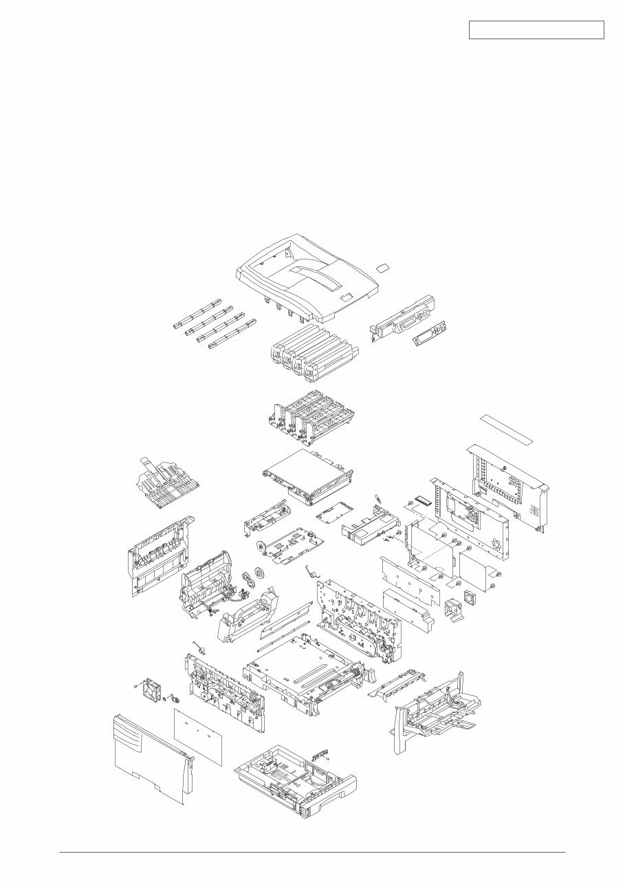
42615101TH Rev.6 10 / Oki Data CONFIDENTIAL 1.2 Printer Configuration The inside of C5450/C5400 printers is composed of the following: • Electrophotographic Processor • Paper Paths • Controller Block (CU and PU) • Operator Panel • Power Units (High Voltage Unit and Low Voltage Unit) Figure 1-2-1 shows the configuration of each printer. Figure 1-2-1
You're Reading a Preview
What's Included?
Lifetime Access
Fast Download Speeds
Online & Offline Access
Access PDF Contents & Bookmarks
Full Search Facility
Print one or all pages of your manual
$31.99
OKI C5450/C5400/C5250/C5200/C5150/C3200n/C3200/C3100 Color LED Page Printer Service Repair Manual
This is a comprehensive Service Repair Manual for the OKI C5450/C5400/C5250/C5200/C5150/C3200n/C3200/C3100 Color LED Page Printer. The manual contains easy-to-read text sections with high-quality diagrams and instructions, providing step-by-step guidance for repairing your OKI machine.
It is a valuable resource for both professional mechanics and DIY enthusiasts, offering technical theory, installation, maintenance, troubleshooting, disassembly, assembly, and repair of OKI products.
Models Covered:
OKI C5450 Color LED Page Printer
OKI C5400 Color LED Page Printer
OKI C5250 Color LED Page Printer
OKI C5200 Color LED Page Printer
OKI C5150 Color LED Page Printer
OKI C3200n Color LED Page Printer
OKI C3200 Color LED Page Printer
OKI C3100 Color LED Page Printer
This Manual Covers:
SPECIFICATIONS
OPERATION DESCRIPTION
PRINTER INSTALLATION
PARTS REPLACEMENT
MAINTENANCE MENU
REGULAR MAINTENANCE
TROUBLESHOOTING PROCEDURES
CONNECTION DIAGRAM
Model Specification: OKI C5450/C5400/C5250/C5200/C5150/C3200n/C3200/C3100 Color LED Page Printer
Total Pages: 249
File Format: PDF
Language: English
Compatibility: All Versions of Windows & Mac, APP ISO, iPhone, iPad, Android, etc.
This manual is in PDF format. It is fully indexed and bookmarked by topic, ensuring easy navigation. The document is an original Adobe file, guaranteeing high-quality printing and readability. You can quickly search the manual to find information in every chapter and print the entire manual or select specific pages. Additionally, you can zoom in on diagrams or pictures for detailed viewing of every part.
By using this manual, you can save time and money on repairs with its easy-to-follow, step-by-step instructions and detailed illustrations covering all areas of repair.
All Service Repair Manuals are available for instant download, eliminating shipping costs and waiting time. Upon payment completion through our secure processor, you will instantly receive the manual. We accept all major credit/debit cards and PayPal.
Reviews
Q&A
Recently Viewed
5,521,897Happy Clients
2,594,462eManuals
1,120,453Trusted Sellers
15Years in Business
Price:
Actual Price:
OKI C5450/C5400/C5250/C5200/C5150/C3200n/C3200/C3100 Color LED Page Printer Service Repair Manual







 Lifetime Access




