Color Inkjet Printer JV33-130/160 ii This manual covers the instructions and useful information to be given to the service personnel on maintenance of the color inkjet printer JV33-130/160. Perform maintenance work according to the instructions given in this manual and the related documents listed below. Constitution This manual consists of the following chapters: CHAPTER 1 Outline of Maintenance Describes the specifications and other information of the printer, including precautions to be taken in maintenance work. CHAPTER 2 Operation Principle and Functions Explains the operation of each unit, and describes the functions and setting items of the printer. CHAPTER 3 Overhaul / Adjustment Describes procedures for removal and reinstallation of major parts. Adjusting or testing methods, or mechanical adjusting methods using jigs and tools are also described. CHAPTER 4 Troubleshooting Describes how to determine the cause of trouble and how to repair the printer. CHAPTER 5 Explanation of Electrical Parts Describes information about PCBs and electrical parts. Related Documents The following documents relate to JV33-130/160. Refer to them whenever necessary. • OPERATION MANUAL (Packed with main unit) • MECHANICAL DRAWING • SETUP GUIDE (for Service Engineers) About this Maintenance Manual
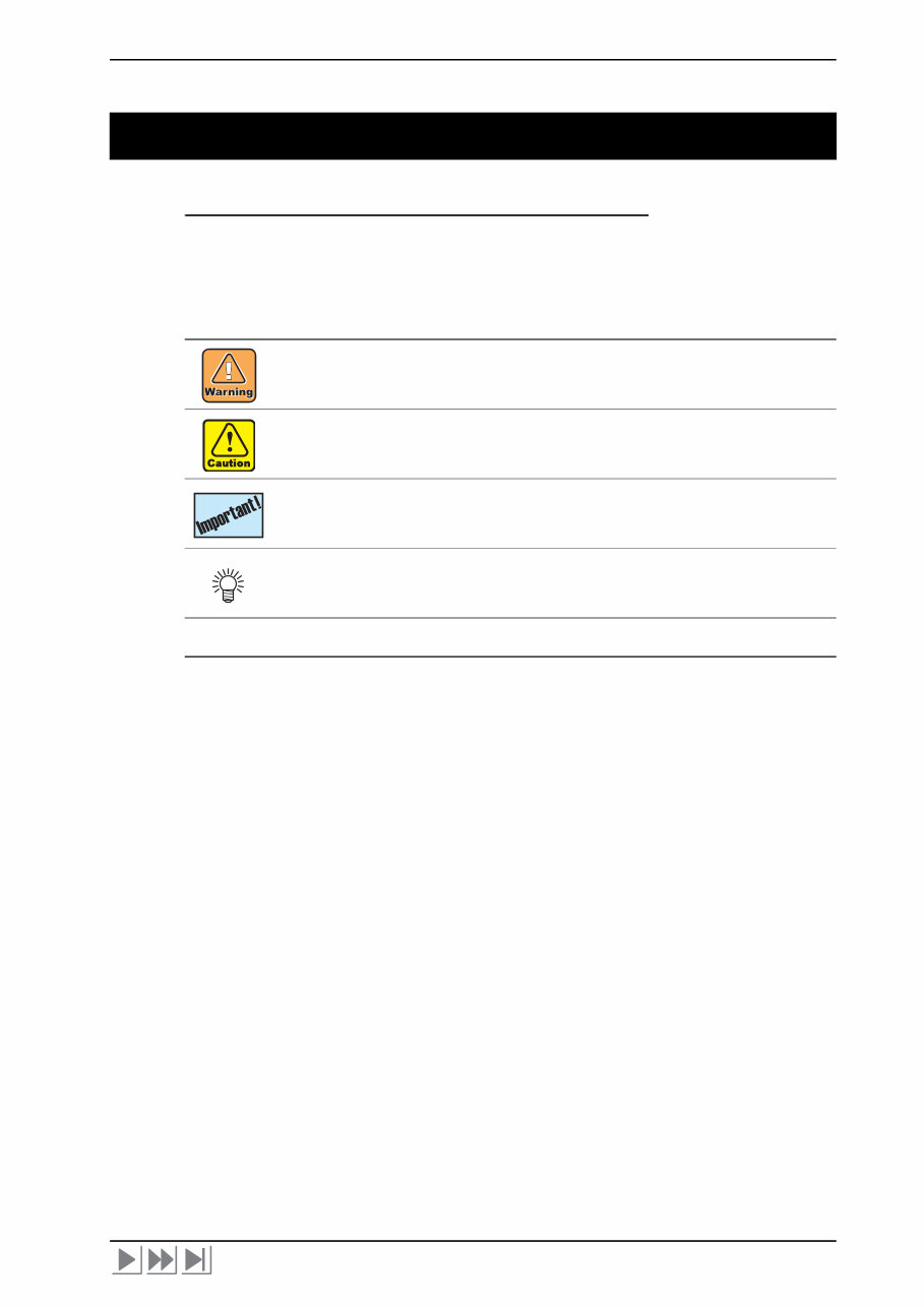
iii Symbols The following symbols are used in this manual. Understand the symbols, and be sure to observe the instructions. Safety Symbols In text Name of symbol Meaning “WARNING” mark Failure to observe the instructions given with this symbol can result in death or serious injuries to personnel. “CAUTION” mark Failure to observe the instructions given with this symbol can result in injuries to personnel or damage to property. “IMPORTANT” mark Important notes on maintenance work are given with this symbol. Understand the instructions thoroughly, and perform maintenance work properly. “Tips” mark Useful information for maintenance work is given with this symbol. (P.1-10) Reference page Related description is given on the page shown by this symbol. Be sure to refer to the specified page.
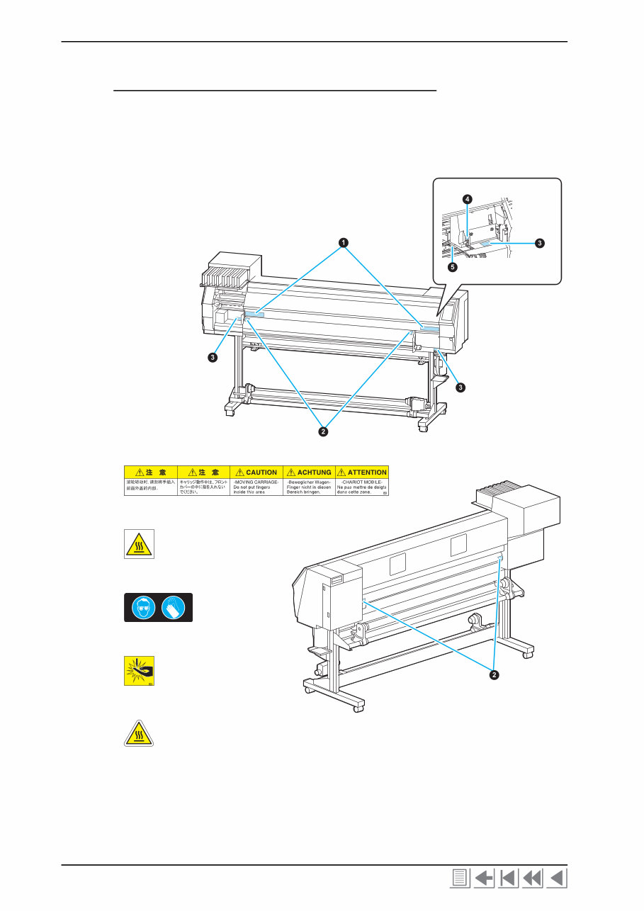
Color Inkjet Printer JV33-130/160 iv Caution Label A caution label is stuck on the printer as shown below. Check the label before work. If it is illegible due to stains or coming off, replace it with a new one after getting user's consent. Locations of labels ~ Front ~ ~ Rear ~ ➊ (Reorder: M901549) ➋ (Reorder: M903239) ➌ (Reorder: M903330) ➍ (Reorder: M903405) ➎ (Reorder: M904810) The front cover is open. Those are put on the right and left media holders.
v Contents Outline of Maintenance 1-1. Precautions in Maintenance ....................................................................... 1-2 1-1-1. Notes on repair ................................................................................. 1-2 1-1-2. Preliminary checks ........................................................................... 1-3 1-2. Tools required for maintenance work ........................................................ 1-4 1-2-1. Tools to be used at disassembly and reassembly ............................. 1-4 1-2-2. Adjustment tools .............................................................................. 1-4 1-3. Specifications of the main unit ................................................................... 1-5 Operation Principle and Functions 2-1. Operation Principle ..................................................................................... 2-2 2-1-1. Sequence at Power-on ...................................................................... 2-2 2-1-2. Origin Point Detection .................................................................... 2-2 2-1-3. Set Up ............................................................................................... 2-3 2-1-4. Media Detection ............................................................................... 2-3 2-1-5. Sequence of Maintenance Function ................................................. 2-4 2-1-6. Ink System ....................................................................................... 2-7 2-2. Functions .................................................................................................... 2-20 2-2-1. ADJUST Function ......................................................................... 2-20 2-2-2. TEST Function ............................................................................... 2-27 2-2-3. Special Key Function ..................................................................... 2-38 2-2-4. PARAMETER Function ................................................................ 2-39 2-3. Operation Flow .......................................................................................... 2-40 2-3-1. Outline ............................................................................................ 2-40 2-3-2. SETUP ........................................................................................... 2-41 2-3-3. MAINTENANCE .......................................................................... 2-43 2-3-4. MACHINE SET ............................................................................. 2-46 2-3-5. COMMON SETUP ........................................................................ 2-47 2-3-6. INFORMATION ............................................................................ 2-48 2-3-7. ADJUST ......................................................................................... 2-49 2-3-8. TEST .............................................................................................. 2-52 2-3-9. PARAMETER ................................................................................ 2-56 Overhaul / Adjustment 3-1. Outline .......................................................................................................... 3-2 3-1-1. Precautions for disassembly and reassembly ................................... 3-2 3-1-2. Tools and jigs ................................................................................... 3-3 3-2. Overhaul of Covers ...................................................................................... 3-4 3-3. Overhaul of Ink-related Parts .................................................................... 3-6 3-3-1. Head Unit ......................................................................................... 3-7 3-3-2. Pump Motor ................................................................................... 3-12
Color Inkjet Printer JV33-130/160 vi 3-3-3. Capping Assembly .......................................................................... 3-13 3-3-4. Major Parts for Washing Cartridge Assembly ................................ 3-15 3-4. Overhaul of PCBs ....................................................................................... 3-18 3-4-1. Main PCB ....................................................................................... 3-19 3-4-2. Station PCB .................................................................................... 3-25 3-5. Overhaul of Sensors ................................................................................... 3-26 3-6. Overhaul of Driving Parts ......................................................................... 3-27 3-6-1. X-axis Motor ................................................................................... 3-28 3-6-2. Y-axis Motor ................................................................................... 3-31 3-6-3. Y-axis Drive Pulley ......................................................................... 3-35 3-6-4. Y Drive Belt .................................................................................... 3-39 3-6-5. Wiper Unit ...................................................................................... 3-42 3-7. Overhaul of Other Parts ............................................................................ 3-44 3-7-1. Cutter Unit Assembly ..................................................................... 3-45 3-7-2. Linear scale ..................................................................................... 3-48 3-7-3. Adjustment of the station height ..................................................... 3-50 Troubleshooting 4-1. Outline ........................................................................................................... 4-2 4-1-1. Rough identification of the source of the trouble ............................. 4-2 4-1-2. Checking procedure .......................................................................... 4-2 4-2. Troubles for which error messages are displayed ..................................... 4-4 4-2-1. Error messages and corrective measures .......................................... 4-4 4-2-2. Warning messages and corrective measures ................................... 4-10 Explanation of Electrical Parts 5-1. Outline ........................................................................................................... 5-2 5-1-1. Operation Explanation ...................................................................... 5-3 5-1-2. Power Supply .................................................................................... 5-4 5-2. Circuit Board Specifications ....................................................................... 5-6 5-2-1. Main PCB ......................................................................................... 5-6 5-2-2. PRAM PCB ...................................................................................... 5-7 5-2-3. Station PCB ...................................................................................... 5-7 5-2-4. X-axis motor relay PCB ................................................................... 5-8 5-2-5. Ink slider PCB .................................................................................. 5-9 5-2-6. Keyboard PCB .................................................................................. 5-9 5-2-7. Encoder PCB .................................................................................... 5-9 5-2-8. Take-up PCB ..................................................................................... 5-9 5-2-9. Head memory PCB ......................................................................... 5-10 5-2-10. LED PCB ........................................................................................ 5-10 5-3. Electronic block diagram ........................................................................... 5-11 5-3-1. Connection diagram inside main unit ............................................. 5-11 5-3-2. Connection diagram outside main unit ........................................... 5-13
1-1 Contents 1-1. Precautions in Maintenance ...................................... 1-2 1-1-1. Notes on repair ......................................................... 1-2 1-1-2. Preliminary checks ................................................... 1-3 1-2. Tools required for maintenance work ....................... 1-4 1-2-1. Tools to be used at disassembly and reassembly ..... 1-4 1-2-2. Adjustment tools ...................................................... 1-4 1-3. Specifications of the main unit .................................. 1-5 CHAPTER 1 Outline of Maintenance
Color Inkjet Printer JV33-130/160 1-2 1-1. Precautions in Maintenance 1-1-1. Notes on repair Observe the following precautions in maintenance work. Be sure to fully understand precautions given in “For safe operation” in the operation manual for the JV33 series. Some error conditions observed may be due to misoperation. First judge whether or not the error condition is caused by misoperation. Provide adequate space for the maintenance work. When performing tests with the electrical circuit box open, be careful not to receive an electric shock from any live part and not to drop screws or any other parts into the circuit box. Take care to avoid insufficient insertion or skewed insertion of any connector or FFC. Do not touch the FFC directly. Doing so may cause contact failure. Move the lever on the FFC connector up or down gently to release or lock the connector, since the lever breaks easily. In the case where it is necessary to conduct maintenance works with the power on, carefully observe the movement of the head. (Keep any part of your body away from the moving parts.) Shift the media (in the X-direction) and the head (in the Y-direction) using the jog keys. If it is necessary to shift the paper and the head by hand with the power turned off, exercise care to shift them slowly. Be sure to turn the power off and unplug the power cable from the main body inlet before starting work. To prevent the ink from getting into your eyes, be sure to wear safety goggles and gloves when cleaning the print head or replacing the S pump L assembly or if the ink is anticipated to scatter. If the ink sticks to your hand, the skin may be get rough and dry. Danger of explosion if battery is incorrectly replaced. Replace only with the same or equivalent type recommended by the manufacture. Dispose of used batteries according to the manufacturer’s instructions. Take sufficient care so that leaked ink does not adhere to other parts. Ink droplets attached to FPCs or connectors may cause shortcircuit or a bad electric contact at inserting/removing a damper, thereby the ink discharge trouble or breakage of head/PCB may occur. Properly and carefully connect the FFC cable of the ink slider PCB from the main PCB according to the connector number. Failure to do so may cause a breakage of the PCB because of short-circuit of the power supply. Pay sufficient attention on arrangement of 2 FFC cables connecting the ink slider PCB to the head. Wrong arrangement of the FFC cables causes short-circuit of the power supply. Do not turn off the power during firmware upgrading. Doing so may disable restarting.
Precautions in Maintenance 1-3 Do not tilt the printer with the ink cartridges filled with ink. Doing so can give rise to leakage of ink. In principle, the following procedures should be taken in prior to the transportation and the transportation should be conducted using exclusive packaging material. 1. Remove the ink from the tube with MAINTENANCE in [HD.MAINTENANCE]- [DISCHARGE&WASH] or [#ADJUST] - [HEAD WASH]. 2. Remove the cleaner from the tube with MAINTENANCE in [HD.MAINTENANCE] - [MaintWashLiquid] (if this action is not performed in Step 1.) 3. Detach the waste ink tank. 4. Fix the head with the head stopper. (As for the detail, see Setup Guide) If the main unit is removed from the legs and placed directly on the floor, be careful of the following points. • Unplug the take-up unit power cord. • Remove the ink waste tank and the fitting bracket. (Plug the tube up with a cloth to prevent ink from spilling over.) 1-1-2. Preliminary checks Before starting work, make sure that the following conditions are all met. The following conditions for the power supply system are all met: • The power supply voltage must be within the specification limits. • The printer must be grounded properly. • The power cable must be free from damage, broken wire, etc. Many cables must not be connected to one outlet. • Connected to an electrical outlet with a removable plug in cases where smoke or flame has been emitted from the socket. Make sure that the printer is not located under any of the following conditions: • In a place where the printer is exposed to direct sunlight. • On an inclined surface. • In an environment of too high or low temperature, or too high or low humidity, or in a place where temperature or humidity varies significantly. • In a place where vibration occurs. • In a place where the printer is exposed to direct air flow from an air conditioner or the like. • Around a place where flame is used. • In a dusty atmosphere. • Around a place where strong electromagnetic waves are generated. The media (sheets) to be used must conform to the specifications.
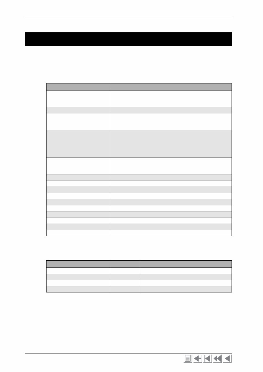
Color Inkjet Printer JV33-130/160 1-4 1-2. Tools required for maintenance work The tables below show the tools and measuring instruments required for maintenance work. 1-2-1. Tools to be used at disassembly and reassembly 1-2-2. Adjustment tools Name Remarks Phillips screwdriver Type 1 Type 2 Type 2 For M2 For M3 to5 (L=260 or more) for M3 to 5 Slotted screwdriver Long side 2.5 mm for removing E-rings Spanner (Box wrench) Width across flats: 5 mm Width across flats: 5.5 mm Width across flats: 7 mm Hexagon wrench 1.5mm for M3 SSWP 2.0mm for M4 SSWP 2.5mm for M3 cap bolts 5.0mm for M6 cap bolts 6.0mm for M8 cap bolts Spanner Width across flats: 5.0 mm Width across flats: 5.5 mm for M3 nuts and hexagon stud Width across flats: 7.0 mm for M4 nuts Tweezers To prevent the cable from being pulled when disconnecting the connector. Long-nose pliers Nippers Soldering iron, Solder Scale 150, 500 mm Loupe About 50x to 60x magnification Protection glasses Gloves To keep hands clean, and for safety. Adhesive agent LOCKTITE242 (for locking screws) Insulation lock L=150 or less (UL-approved product) Name Code Remarks Trimmer adjustment screwdriver For adjustment of trimmers on the power supply PCB. Tester Bar type tension gauge 500 g Ink line airtight tester OPT-J0094
This is a comprehensive Service Repair Manual for the Mimaki JV33-160, JV33-130. The manual contains easy-to-read text sections with high-quality diagrams and step-by-step instructions for repairing your Mimaki machine. It is designed to facilitate learning of technical theory, installation, maintenance, troubleshooting, disassembly, assembly, and repair of Mimaki products.
This Manual Covers:
CHAPTER 1. Outline of Maintenance
CHAPTER 2. Operation Principle and Functions
CHAPTER 3. Overhaul / Adjustment
CHAPTER 4. Troubleshooting
CHAPTER 5. Explanation of Electrical Parts
Model Specification: Mimaki JV33-160, JV33-130
Total Pages: 152
File Format: PDF
Requirements: Adobe Reader
Language: English
Compatibility: All Versions of Windows & Mac, APP ISO, Iphone, Ipad, Android etc...
This manual is in PDF format. The Service Manual is fully indexed and bookmarked by topic, ensuring ease of navigation. It is an original Adobe document, guaranteeing high quality and perfect printing. The PDF can be quickly searched to find information in every chapter. You have the flexibility to print the entire manual or select specific pages. Additionally, you can zoom in on any diagram or picture for detailed viewing of every part.
By using this manual, you can save time and money by performing your own repairs. The manual provides easy-to-follow, step-by-step instructions and illustrations for all areas of repair.
All Service Repair Manuals are available for instant download, eliminating shipping costs and the wait for a CD or paper manual to arrive. Upon payment completion through our secure processor, you will instantly receive this manual. We accept all major credit/debit cards and PayPal.