Confidential PRECAUTIONS Precautionary notations throughout the text are categorized relative to 1) Personal injury and 2) damage to equipment. DANGER Signals a precaution which, if ignored, could result in serious or fatal personal injury. Great caution should be exercised in performing procedures preceded by DANGER Headings. WARNING Signals a precaution which, if ignored, could result in damage to equipment. The precautionary measures itemized below should always be observed when performing repair/maintenance procedures. DANGER 1. ALWAYS DISCONNECT THE PRODUCT FROM THE POWER SOURCE AND PERIPHERAL DEVICES PERFORMING ANY MAINTENANCE OR REPAIR PROCEDURES. 2. NO WORK SHOULD BE PERFORMED ON THE UNIT BY PERSONS UNFAMILIAR WITH BASIC SAFETY MEASURES AS DICTATED FOR ALL ELECTRONICS TECHNICIANS IN THEIR LINE OF WORK. 3. WHEN PERFORMING TESTING AS DICTATED WITHIN THIS MANUAL, DO NOT CONNECT THE UNIT TO A POWER SOURCE UNTIL INSTRUCTED TO DO SO. WHEN THE POWER SUPPLY CABLE MUST BE CONNECTED, USE EXTREME CAUTION IN WORKING ON POWER SUPPLY AND OTHER ELECTRONIC COMPONENTS. 4. WHEN DISASSEMBLING OR ASSEMBLING A PRODUCT, MAKE SURE TO WEAR GLOVES TO AVOID INJURIER FROM METAL PARTS WITH SHARP EDGES. WARNING 1. REPAIRS ON EPSON PRODUCT SHOULD BE PERFORMED ONLY BY AN EPSON CERTIFIED REPAIR TECHNICIAN. 2. MAKE CERTAIN THAT THE SOURCE VOLTAGES IS THE SAME AS THE RATED VOLTAGE, LISTED ON THE SERIAL NUMBER/RATING PLATE. IF THE EPSON PRODUCT HAS A PRIMARY AC RATING DIFFERENT FROM AVAILABLE POWER SOURCE, DO NOT CONNECT IT TO THE POWER SOURCE. 3. ALWAYS VERIFY THAT THE EPSON PRODUCT HAS BEEN DISCONNECTED FROM THE POWER SOURCE BEFORE REMOVING OR REPLACING PRINTED CIRCUIT BOARDS AND/OR INDIVIDUAL CHIPS. 4. IN ORDER TO PROTECT SENSITIVE MICROPROCESSORS AND CIRCUITRY, USE STATIC DISCHARGE EQUIPMENT, SUCH AS ANTI-STATIC WRIST STRAPS, WHEN ACCESSING INTERNAL COMPONENTS. 5. REPLACE MALFUNCTIONING COMPONENTS ONLY WITH THOSE COMPONENTS BY THE MANUFACTURE; INTRODUCTION OF SECOND-SOURCE ICs OR OTHER NON-APPROVED COMPONENTS MAY DAMAGE THE PRODUCT AND VOID ANY APPLICABLE EPSON WARRANTY. 6. WHEN USING COMPRESSED AIR PRODUCTS; SUCH AS AIR DUSTER, FOR CLEANING DURING REPAIR AND MAINTENANCE, THE USE OF SUCH PRODUCTS CONTAINING FLAMMABLE GAS IS PROHIBITED.
Confidential About This Manual This manual describes basic functions, theory of electrical and mechanical operations, maintenance and repair procedures of the printer. The instructions and procedures included herein are intended for the experienced repair technicians, and attention should be given to the precautions on the preceding page. Manual Configuration This manual consists of six chapters and Appendix. CHAPTER 1.PRODUCT DESCRIPTIONS Provides a general overview and specifications of the product. CHAPTER 2.OPERATING PRINCIPLES Describes the theory of electrical and mechanical operations of the product. CHAPTER 3.TROUBLESHOOTING Describes the step-by-step procedures for the troubleshooting. CHAPTER 4.DISASSEMBLY / ASSEMBLY Describes the step-by-step procedures for disassembling and assembling the product. CHAPTER 5.ADJUSTMENT Provides Epson-approved methods for adjustment. CHAPTER 6.MAINTENANCE Provides preventive maintenance procedures and the lists of Epson- approved lubricants and adhesives required for servicing the product. APPENDIX Provides the following additional information for reference: • Exploded Diagram • Parts List Symbols Used in this Manual Various symbols are used throughout this manual either to provide additional information on a specific topic or to warn of possible danger present during a procedure or an action. Be aware of all symbols when they are used, and always read NOTE, CAUTION, or WARNING messages. Indicates an operating or maintenance procedure, practice or condition that is necessary to keep the product’s quality. Indicates an operating or maintenance procedure, practice, or condition that, if not strictly observed, could result in damage to, or destruction of, equipment. May indicate an operating or maintenance procedure, practice or condition that is necessary to accomplish a task efficiently. It may also provide additional information that is related to a specific subject, or comment on the results achieved through a previous action. Indicates an operating or maintenance procedure, practice or condition that, if not strictly observed, could result in injury or loss of life. Indicates that a particular task must be carried out according to a certain standard after disassembly and before re-assembly, otherwise the quality of the components in question may be adversely affected. A D J U S T M E N T R E Q U I R E D C A U T I O N C H E C K P O I N T W A R N I N G
Confidential Revision Status Revision Date of Issue Description A August 9, 2007 First Release B May 20, 2008 Revised Contents Descriptions about Epson Stylus TX200/TX203/SX200/SX205/TX400/TX405/SX400/SX405 are added. Chapter 1 “CHECK POINT” has been added in 1.1 Features (p9). Descriptions have been added in 1.1 Features (p9). Made changes in Table 1-2 “Product No. of Ink Cartridges” (p10). Made changes in Table 1-6 “Supported Paper” (p13). Made changes in Table 1-10 “Primary Power Specifications” (p16). Made changes in 1.4.3 Durability (p17). Made changes in 1.4.5 Safety Approvals (Safety standards/EMI) (p17). Made changes in Table 1-13 “Device ID” (p17). “CAUTION” has been added in 1.5.2 Memory Card Slots (p18). Made changes in Table 1-15 “List of Supported Memory Card” (p18). Made changes in Figure 1-11 “Nozzle Check Pattern” (p39). Chapter 2 2.3 Electrical Circuit Operating Principles has been deleted. Chapter 3 Made changes in 3.1 Overview (p59). Made changes in Table 3-12 “Check point for Memory Card error according to each phenomenon” (p77). Chapter 4 “CHECK POINT” has been added in 4.1 Overview (p91). Chapter 7 7.2 Electrical Circuits has been deleted. C July 15, 2008 Revised Contents All Chapter The model name; Epson Stylus NX200/TX209/NX400/TX409 are added.
EPSON Stylus CX7300/CX7400/DX7400/NX200/TX200 series/SX200 series/Stylus CX8300/CX8400/DX8400/NX400/TX400 series/SX400 series Revision C 6 Confidential Contents Chapter 1 PRODUCT DESCRIPTION 1.1 Features.................................................................................................................. 9 1.2 Printing Specifications......................................................................................... 10 1.2.1 Basic Specifications .................................................................................... 10 1.2.2 Ink Cartridge ............................................................................................... 10 1.2.3 Print Mode .................................................................................................. 11 1.2.4 Supported Paper .......................................................................................... 13 1.2.5 Printing Area............................................................................................... 15 1.3 Scanner Specifications......................................................................................... 15 1.3.1 Scanning Range .......................................................................................... 15 1.4 General Specifications ......................................................................................... 16 1.4.1 Electrical Specifications ............................................................................. 16 1.4.2 Environmental Conditions .......................................................................... 16 1.4.3 Durability .................................................................................................... 17 1.4.4 Acoustic Noise ............................................................................................ 17 1.4.5 Safety Approvals (Safety standards/EMI) .................................................. 17 1.5 Interface ............................................................................................................... 17 1.5.1 USB Interface ............................................................................................. 17 1.5.2 Memory Card Slots ..................................................................................... 18 1.6 Control Panel ....................................................................................................... 19 1.6.1 Operation Buttons & LEDs ........................................................................ 19 1.6.2 Control Panel Functions in Each Mode ...................................................... 21 1.7 Specification for Each Function .......................................................................... 29 1.7.1 Stand-alone Copy Function ........................................................................ 29 1.7.2 Memory Card Direct Print Function ........................................................... 31 1.7.3 Camera Direct Print Function (USB Direct Print/PictBridge) ................... 36 1.7.4 Reprint/Restore Photos Function (CX8300/TX400 series only) ................ 38 1.7.5 Setup Mode ................................................................................................. 39 Chapter 2 OPERATING PRINCIPLES 2.1 Overview ............................................................................................................. 42 2.1.1 Printer Mechanism...................................................................................... 42 2.1.2 Motors & Sensors ....................................................................................... 43 2.1.3 Printhead ..................................................................................................... 44 2.1.4 Carriage Mechanism................................................................................... 46 2.1.5 Paper Loading/Paper Feed Mechanism ...................................................... 47 2.1.6 Ink System Mechanism .............................................................................. 52 2.1.7 Ink Sequence............................................................................................... 55 2.2 Scanner Mechanism ............................................................................................ 56 2.2.1 Scanner Carriage Mechanism ..................................................................... 56 Chapter 3 TROUBLESHOOTING 3.1 Overview ............................................................................................................. 59 3.1.1 Specified Tools ........................................................................................... 59 3.1.2 Preliminary Checks..................................................................................... 59 3.2 Troubleshooting................................................................................................... 60 3.2.1 Motor and Sensor Troubleshooting ............................................................ 60 3.3 Error Indications and Fault Occurrence Causes .................................................. 61 3.3.1 Error Indication Method ............................................................................. 61 3.3.2 Troubleshooting by Error Message ............................................................ 65 3.3.3 Superficial Phenomenon-Based Troubleshooting ...................................... 83
EPSON Stylus CX7300/CX7400/DX7400/NX200/TX200 series/SX200 series/Stylus CX8300/CX8400/DX8400/NX400/TX400 series/SX400 series Revision C 7 Confidential Chapter 4 DISASSEMBLY/ASSEMBLY 4.1 Overview ............................................................................................................. 91 4.1.1 Precautions .................................................................................................. 91 4.1.2 Tools ........................................................................................................... 92 4.1.3 Work Completion Check ............................................................................ 92 4.1.4 Procedural Differences between the Models .............................................. 94 4.2 Disassembly Procedures ...................................................................................... 95 4.3 Removing the Housing ........................................................................................ 96 4.3.1 Paper Support Assy..................................................................................... 96 4.3.2 Stacker Assy ............................................................................................... 96 4.3.3 Document Cover/ASF Cover ...................................................................... 97 4.3.4 Scanner Unit/Hinge .................................................................................... 98 4.3.5 Upper Housing/Card Slot Cover ............................................................... 100 4.4 Removing the Circuit Boards ............................................................................ 101 4.4.1 Main Board Unit ....................................................................................... 101 4.4.2 Panel Unit/LCD Unit ................................................................................ 103 4.4.3 Power Supply Unit .................................................................................... 105 4.5 Disassembling the Printer Mechanism .............................................................. 107 4.5.1 Printhead ................................................................................................... 107 4.5.2 CR Scale ................................................................................................... 109 4.5.3 Hopper ...................................................................................................... 110 4.5.4 Removing the Printer Mechanism (Lower Housing)................................ 111 4.5.5 Left Frame ................................................................................................ 113 4.5.6 Front Frame/Right Frame ......................................................................... 114 4.5.7 Star Wheel Holder Assy ........................................................................... 116 4.5.8 EJ Roller ................................................................................................... 116 4.5.9 PF Encoder Sensor .................................................................................... 117 4.5.10 PF Scale .................................................................................................. 118 4.5.11 PF Motor ................................................................................................. 119 4.5.12 CR Motor ................................................................................................ 120 4.5.13 Main Frame Assy.................................................................................... 122 4.5.14 CR Unit ................................................................................................... 124 4.5.15 Upper Paper Guide ................................................................................. 126 4.5.16 ASF Unit ................................................................................................. 126 4.5.17 Ink System Unit ...................................................................................... 128 4.5.18 Front Paper Guide ................................................................................... 131 4.5.19 PF Roller ................................................................................................. 132 4.5.20 Waste Ink Pads ....................................................................................... 133 4.6 Disassembling the Scanner Unit........................................................................ 134 4.6.1 Upper/Front Scanner Housing .................................................................. 134 4.6.2 Scanner Carriage Unit .............................................................................. 135 4.6.3 Scanner Motor Unit .................................................................................. 138 4.7 Differences in Disassembling/Reassembling Stylus CX7300/TX200 series .... 139 4.7.1 Panel Unit (CX7300/TX200 series) ......................................................... 139 Chapter 5 ADJUSTMENT 5.1 Adjustment Items and Overview ....................................................................... 142 5.1.1 Servicing Adjustment Item List ................................................................ 142 5.1.2 Required Adjustments .............................................................................. 144 5.2 Using the Adjustment Program ......................................................................... 146 5.2.1 TOP Margin Adjustment .......................................................................... 146 5.2.2 First Dot Position Adjustment .................................................................. 146 5.2.3 Head Angular Adjustment ........................................................................ 147 5.2.4 Bi-D Adjustment....................................................................................... 148 5.2.5 PF Adjustment .......................................................................................... 148 5.2.6 PF Band Adjustment ................................................................................. 150 5.2.7 Bottom Margin Adjustment ...................................................................... 150 Chapter 6 MAINTENANCE 6.1 Overview ........................................................................................................... 152 6.1.1 Cleaning .................................................................................................... 152 6.1.2 Service Maintenance................................................................................. 152 6.1.3 Lubrication................................................................................................ 153 Chapter 7 APPENDIX 7.1 Exploded Diagram / Parts List .......................................................................... 159
Confidential CHAPTER 1 PRODUCT DESCRIPTION
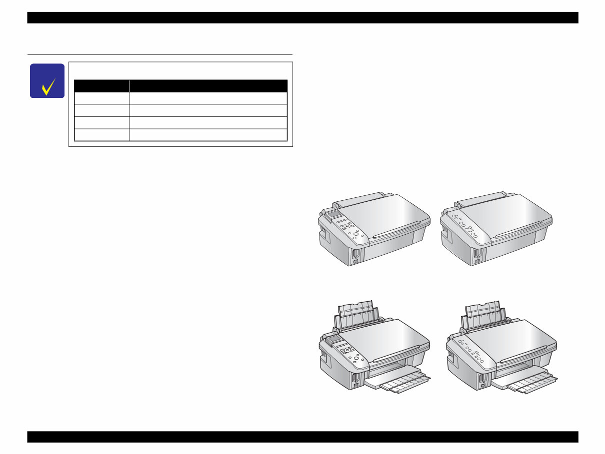
EPSON Stylus CX7300/CX7400/DX7400/NX200/TX200 series/SX200 series/Stylus CX8300/CX8400/DX8400/NX400/TX400 series/SX400 series Revision C PRODUCT DESCRIPTION Features 9 Confidential 1.1 Features EPSON Stylus CX7300/TX200/CX8300/TX400 series are color ink-jet printers with scanner function and have the following features. The difference in appearance between the two models is LCD; CX8300/TX400 series is equipped with LCD, and CX7300/TX200 series is not equipped with it. Available Functions Printer Printing from a computer or directly printing from a memory card. Scanner Scanning from a computer Copy Stand alone copy using the scanning and printing functions Memory card slot Available as USB memory card slot for PC Color LCD (CX8300/TX400 series only) • 2.5-inch color TFD LCD (CX8300 series) • 2.5-inch color α-TFT LCD (TX400 series) High speed & High quality Maximum print resolution: SMGA 5760 (H) x 1440 (V) dpi D4-chips Turbo II Printhead achieves higher print speed than ever. (Black: 90 nozzles x 1, Color: 90 nozzles x 1 per color) Four independent ink cartridges is installed. Newly developed pigment ink is employed. Borderless printing on specified EPSON brand paper is available. Dimensions Stylus CX7300/CX8300 series • Dimensions* 1 : 450 mm (W) x 340 mm (D) x 179 mm (H) • Weight* 2 : CX8300 series: 5.9 kg CX7300 series: 5.8 kg Stylus TX200/TX400 series • Dimensions* 1 : 450 mm (W) x 342 mm (D) x 182 mm (H) • Weight* 2 : TX400 series: 5.9 kg TX200 series: 5.8 kg *1 :Paper support and stacker are closed. Rubber feet are excluded. *2 :Excluding the weight of ink cartridges and power cable. Figure 1-1. External View C H E C K P O I N T In this chapter, the product names are called as follows: Notation Product name CX7300 series Stylus CX7300/CX7400/DX7400 TX200 series Stylus NX200/TX200/TX203/TX209/SX200/SX205 CX8300 series Stylus CX8300/CX8400/DX8400 TX400 series Stylus NX400/TX400/TX405/TX409/SX400/SX405 Paper Support & Stacker are Closed CX8300/TX400 series CX7300/TX200 series CX8300/TX400 series CX7300/TX200 series
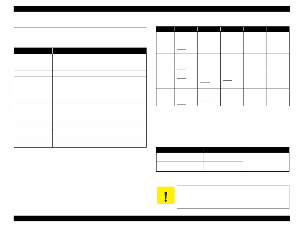
EPSON Stylus CX7300/CX7400/DX7400/NX200/TX200 series/SX200 series/Stylus CX8300/CX8400/DX8400/NX400/TX400 series/SX400 series Revision C PRODUCT DESCRIPTION Printing Specifications 10 Confidential 1.2 Printing Specifications 1.2.1 Basic Specifications 1.2.2 Ink Cartridge The product numbers of the EPSON ink cartridges for this printer are shown below. Note *1 : Available only with CX8300/TX400 series. *2 : Available only with CX7300/TX200/TX400 series. *3 : Available only with CX7300/CX8300 series. *4 : Available only with TX200/TX400 series. Shelf life Two years from production date (if unopened), six months after opening package. Storage Temperature Dimension 12.7 mm (W) x 68 mm (D) x 47 mm (H) Table 1-1. Printer Specifications Item Specification Print method On-demand ink jet Nozzle configuration Black: 90 nozzles x 1 Color: 90 nozzles x 3 (Cyan, Magenta, Yellow) Print direction Bi-directional minimum distance printing, Unidirectional printing Print resolution Horizontal x Vertical (dpi) • 360 x 120 • 1440 x 720 • 360 x 360 • 1440 x 1440 • 360 x 720 • SMGA 5760 x 1440 (2880 x 1440) • 720 x 720 Control code • ESC/P Raster command • ESC/P-R (RGB) command • EPSON Remote command Input buffer size 64 Kbytes Paper feed method Friction feed, using the ASF (Auto Sheet Feeder) Paper path Top feed, front out Paper feed rates T.B.D. mm/sec (at 25.4 mm feed) PF interval Programmable in 0.01764 mm (1/1440 inch) steps Table 1-2. Product No. of Ink Cartridges Color EAI Latin Euro CISMEA Asia Black T0681 (S)* 1 T0691 (2S) T0881 (3S)* 2 T0881 (3S)* 4 T0731H (S) T0731HN (S)* 4 T0731 (2S) T0731N (2S)* 4 T0901 (3S)* 3 T0711H (S) T0711 (2S) T0891 (3S)* 4 T0731H (S) T0731HN (S)* 4 T0731 (2S) T0731N (2S)* 4 T0731HN (S)* 4 T0731 (2S) T0731N (2S)* 4 Cyan T0692 (3S) T0692 (3S)* 4 T0882 (4S)* 2 T0882 (4S)* 4 T0732 (3S) T0732N (3S)* 4 T0712 (3S) T0712 (3S)* 4 T0892 (4S)* 4 T0732 (3S) T0732N (3S)* 4 T0732 (3S) T0732N (3S)* 4 Magenta T0693 (3S) T0693 (3S)* 4 T0883 (4S)* 2 T0883 (4S)* 4 T0733 (3S) T0733N (3S)* 4 T0713 (3S) T0713 (3S)* 4 T0893 (4S)* 4 T0733 (3S) T0733N (3S)* 4 T0733 (3S) T0733N (3S)* 4 Yellow T0694 (3S) T0694 (3S)* 4 T0884 (4S)* 2 T0884 (4S)* 4 T0734 (3S) T0734N (3S)* 4 T0714 (3S) T0714 (3S)* 4 T0894 (4S)* 4 T0734 (3S) T0734N (3S)* 4 T0734 (3S) T0734N (3S)* 4 Table 1-3. Storage Temperature Situation Storage Temperature Limit When stored in individual boxes -20 o C to 40 o C (-4 o F to 104 o F) 1 month max. at 40 o C (104 o F) When installed in main unit -20 o C to 40 o C (-4 o F to 104 o F) C A U T I O N Do not use expired ink cartridges. The ink in the ink cartridge freezes at -16 °C (3.2 o F). It takes about three hours under 25 °C (77 o F) until the ink thaws and becomes usable.
Are you experiencing issues with your Epson Printer? Why spend a fortune on repairs or replacements when you can take matters into your own hands?
This comprehensive service and repair manual is utilized by certified Epson technicians and is designed to assist you in troubleshooting and fixing your printer.
Whether you're a professional mechanic or a DIY enthusiast, this manual contains valuable information for you.
The manual includes detailed chapters covering product description, operating principles, troubleshooting, disassembly/assembly, adjustment, maintenance, and an appendix with an exploded diagram/parts list.
With 158 pages in English, this manual is available in a downloadable format for both Windows and MAC platforms.
Don't wait for shipping - gain instant access after payment and start your repairs immediately!
If you're in need of a specific service manual, reach out to us. With one of the largest service manual databases, we may be able to assist you.