


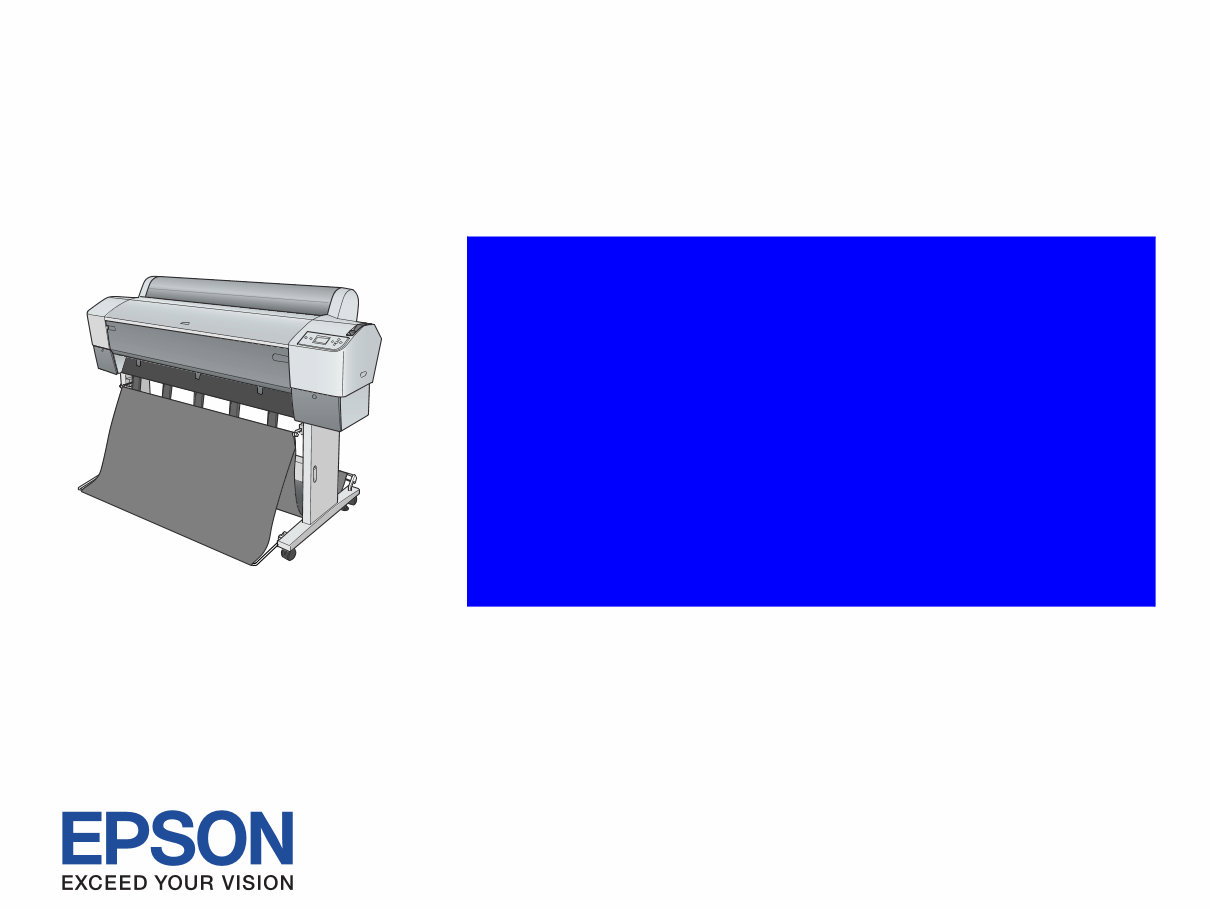
EPSON Stylus Pro 7400/7450/7800/7880/7880C
9400/9450/9800/9880/9880C
Large Format Color Inkjet Printer
SERVICE MANUAL
SEIJ05002

Notice:
All rights reserved. No part of this manual may be reproduced, stored in a retrieval system, or transmitted in any form or by any means, electronic,
mechanical, photocopying, recording, or otherwise, without the prior written permission of SEIKO EPSON CORPORATION.
The contents of this manual are subject to change without notice.
All effort have been made to ensure the accuracy of the contents of this manual. However, should any errors be detected, SEIKO EPSON would greatly
appreciate being informed of them.
The above not withstanding SEIKO EPSON CORPORATION can assume no responsibility for any errors in this manual or the consequences thereof.
EPSON is a registered trademark of SEIKO EPSON CORPORATION.
General Notice: Other product names used herein are for identification purpose only and may be trademarks or registered trademarks of their
respective owners. EPSON disclaims any and all rights in those marks.
Copyright © 2007 SEIKO EPSON CORPORATION.
Imaging Product CS,PL & Environmental Management

PRECAUTIONS
Precautionary notations throughout the text are categorized relative to 1) Personal injury and 2) Damage to equipment.
DANGER Signals a precaution which, if ignored, could result in serious or fatal personal injury. Great caution should be exercised in performing
procedures preceded by DANGER Headings.
WARNING Signals a precaution which, if ignored, could result in damage to equipment.
The precautionary measures itemized below should always be observed when performing repair/maintenance procedures.
DANGER
1. ALWAYS DISCONNECT THE PRODUCT FROM THE POWER SOURCE AND PERIPHERAL DEVICES PERFORMING ANY MAINTENANCE OR
REPAIR PROCEDURES.
2. NO WORK SHOULD BE PERFORMED ON THE UNIT BY PERSONS UNFAMILIAR WITH BASIC SAFETY MEASURES AS DICTATED FOR ALL
ELECTRONICS TECHNICIANS IN THEIR LINE OF WORK.
3. WHEN PERFORMING TESTING AS DICTATED WITHIN THIS MANUAL, DO NOT CONNECT THE UNIT TO A POWER SOURCE UNTIL
INSTRUCTED TO DO SO. WHEN THE POWER SUPPLY CABLE MUST BE CONNECTED, USE EXTREME CAUTION IN WORKING ON POWER
SUPPLY AND OTHER ELECTRONIC COMPONENTS.
WARNING
1. REPAIRS ON EPSON PRODUCT SHOULD BE PERFORMED ONLY BY AN EPSON CERTIFIED REPAIR TECHNICIAN.
2. MAKE CERTAIN THAT THE SOURCE VOLTAGES IS THE SAME AS THE RATED VOLTAGE, LISTED ON THE SERIAL NUMBER/RATING
PLATE. IF THE EPSON PRODUCT HAS A PRIMARY AC RATING DIFFERENT FROM AVAILABLE POWER SOURCE, DO NOT CONNECT IT TO
THE POWER SOURCE.
3. ALWAYS VERIFY THAT THE EPSON PRODUCT HAS BEEN DISCONNECTED FROM THE POWER SOURCE BEFORE REMOVING OR
REPLACING PRINTED CIRCUIT BOARDS AND/OR INDIVIDUAL CHIPS.
4. IN ORDER TO PROTECT SENSITIVE MICROPROCESSORS AND CIRCUITRY, USE STATIC DISCHARGE EQUIPMENT, SUCH AS ANTI-STATIC
WRIST STRAPS, WHEN ACCESSING INTERNAL COMPONENTS.
5. REPLACE MALFUNCTIONING COMPONENTS ONLY WITH THOSE COMPONENTS BY THE MANUFACTURE; INTRODUCTION OF SECOND-
SOURCE ICs OR OTHER NON-APPROVED COMPONENTS MAY DAMAGE THE PRODUCT AND VOID ANY APPLICABLE EPSON WARRANTY.
6. WHEN AIR DUSTER IS USED ON THE REPAIR AND THE MAINTENANCE WORK, THE USE OF THE AIR DUSTER PRODUCTS CONTAINING
THE INFLAMMABLE GAS IS PROHIBITED.

About This Manual
This manual describes basic functions, theory of electrical and mechanical operations, maintenance and repair procedures of the printer. The instructions and procedures included
herein are intended for the experienced repair technicians, and attention should be given to the precautions on the preceding page.
Manual Configuration
This manual consists of six chapters and Appendix.
CHAPTER 1.PRODUCT DESCRIPTIONS
Provides a general overview and specifications of the product.
CHAPTER 2.OPERATING PRINCIPLES
Describes the theory of electrical and mechanical operations of the
product.
CHAPTER 3.TROUBLESHOOTING
Describes the step-by-step procedures for the troubleshooting.
CHAPTER 4.DISASSEMBLY / ASSEMBLY
Describes the step-by-step procedures for disassembling and assembling
the product.
CHAPTER 5.ADJUSTMENT
Provides Epson-approved methods for adjustment.
CHAPTER 6.MAINTENANCE
Provides preventive maintenance procedures and the lists of Epson-
approved lubricants and adhesives required for servicing the product.
APPENDIX Provides the following additional information for reference:
• Connector pin assignments
• Electric circuit boards components layout
• Electrical circuit boards schematics
• Exploded diagram & Parts List
Symbols Used in this Manual
Various symbols are used throughout this manual either to provide additional
information on a specific topic or to warn of possible danger present during a
procedure or an action. Be aware of all symbols when they are used, and always read
NOTE, CAUTION, or WARNING messages.
Indicates an operating or maintenance procedure, practice or condition
that is necessary to keep the product’s quality.
Indicates an operating or maintenance procedure, practice, or condition
that, if not strictly observed, could result in damage to, or destruction of,
equipment.
May indicate an operating or maintenance procedure, practice or
condition that is necessary to accomplish a task efficiently. It may also
provide additional information that is related to a specific subject, or
comment on the results achieved through a previous action.
Indicates an operating or maintenance procedure, practice or condition
that, if not strictly observed, could result in injury or loss of life.

Revision Status
Revision Date of Issue Description
A July 29, 2005 First release
B September 2, 2005 Revised Contents
[All chapters]
• “Weight” has been changed to “mass”.
[Chapter 1]
• “Service Personnel Mode” has been changed to “SERVICEMAN MODE”.
• Descriptions have been added in 1.4.4.35 Power Cleaning (Page 99).
• “CAUTION” in Edge Sensor Level Measurement (Page 118) has been deleted.
[Chapter 2]
• Made changes in 2.2.4 Cleaning Mechanism (Page 171).
• 2.5 Colorimetric Calibration (Color ID) Overview (Page 178) has been added.
[Chapter 4]
• “ADJUSTMENT REQUIRED” has been added in 4.2.4.2 P/S BOARD ASSY. (Page 243).
• “ADJUSTMENT REQUIRED” has been added in 4.2.4.4 BOARD ASSY., SUB (Page 245).
• Made changes and added “REASSEMBLY” in 4.2.5.2 CR MOTOR ASSY. (Page 252).
• “CAUTION” has been added in 4.2.7.4 PUMP CAP ASSY. (Page 298).

B September 2, 2005 [Chapter 5]
• Descriptions have been added in Table 5-1. Parts and Units that Require Adjustments (Page 307).
• Descriptions have been added in Table 5-2. Required Adjustments in the Order of Execution (Page 308).
• Descriptions have been added in Basic Adjustment (Page 311).
• Made changes in Table 5-3. Tools for Adjustments (Page 313).
• Made changes in “System Requirements” in 5.1.7 Adjustment Program Basic Operations (Page 314).
• Made changes in 5.2.2 Cutter Position/Height Adjustment (Page 316).
• Made changes in 5.2.3 Paper Thickness Sensor Position Adjustment (Page 318).
• “Shield Cap” has been changed to “Seal Cap” in 5.2.8 Air Leak Check (Page 324).
• Made changes in 5.3.4 T&B&S (Roll Paper) (Page 334).
• Made changes in 5.3.5 T&B&S + 980mm Band Feed (Page 336).
• Made changes in 5.3.7 Nozzle Bi-D Adjustment (Page 339).
• Made changes in 5.3.8 Print Head Slant Adjustment (PF) (Page 340).
• Made changes in 5.3.9 Print Head Slant Adjustment (CR) (Page 343).
• Made changes in 5.3.10 Ink Mark Sensor Level Adjustment (Page 346).
• Made changes in 5.3.11 Auto Uni-D Adjustment (Page 347).
• Made changes in 5.3.12 Auto Bi-D Adjustment (P.G. 0.8/1.6) (Page 348).
• Made changes in 5.3.13 Ink Mark Sensor Adjustment for Auto Nozzle Check (Page 349).
• Made changes in 5.3.14 Skew Check (Page 351).
• Made changes in 5.3.15 Platen Position Adjustment (Page 352).
• Made changes in 5.3.16 980mm Band Feed Adjustment (Page 354).
• 5.3.22 Colorimetric Calibration (Color ID) (Page 359) have been added.
• Made changes in 5.4.1 Auto Bi-D Adjustment (Page 375).
• Made changes in 5.4.2 Manual Bi-D Adjustment (Page 376).
• Made changes in 5.5.1 Check Nozzle (Page 380).
• Made changes in 5.5.2 Check Alignment (Page 381).
• Made changes in 5.5.3 Print Adjustment Check Pattern (Page 382).
• Made changes in 5.5.4 Check Cutting (Page 383).
• 5.8 Model Setting (when replacing the Main Board) (Page 390) have been added.
Revision Date of Issue Description

C December 15, 2006 Revised Contents
[Chapter 1]
• Table 1-28. Button Functions (Page 35) was modified.
[Chapter 4]
• 4.2.5.8 CARRIAGE UNIT (Page 261) was added.
[Chapter 7]
• 7.2 Circuit Diagrams (Page 405) was revised.
D June 15, 2007 Revised Contents
[All chapters]
• T.B.D. items have been determined.
[Chapter 2]
• Figure 2-2. Carriage Mechanism (Page 159) was modified.
• Figure 2-3. Carriage Mechanical Unit and PG Adjustment Unit (Page 161) was modified.
[Chapter 3]
• Remedy (Page 188) was revised.
[Chapter 4]
• REASSEMBLY was added in 4.2.7.1 PRINT HEAD (Page 281)
[Chapter 5]
• 5.1.4 Required Adjustments by Part or Unit (Page 308) was changed.
• 5.1.6 Tools for Adjustments (Page 313) was changed.
• A misdescription was corrected in 5.2.3 Paper Thickness Sensor Position Adjustment (Page 318)
• A misdescription was corrected in 5.3.6 Cutter Pressure Adjustment (Page 338)
• Required Tool was added in 5.3.16 980mm Band Feed Adjustment (Page 354)
• “Tiny mode” was changed to “F/W update mode” in 5.3.18 NVRAM Back Up and Write (Page 356)
• A misdescription was corrected in 5.3.21 Rear Sensor Adjustment (Page 358)
• 5.8 Model Setting (when replacing the Main Board) (Page 390) was changed.
E September 12, 2007 Revised Contents
[All chapters]
• Information on Stylus Pro 7880/7880C/7450/9880/9880C/9450 has been added.
Revision Date of Issue Description

EPSON Stylus Pro 7400/7450/7800/7880/7880C/9400/9450/9800/9880/9880C Revision E
8
Contents
Chapter 1 Product Description
1.1 Product Description ............................................................................................ 12
1.1.1 Features ...................................................................................................... 12
1.1.2 Difference between 8 color and 4 color machines ..................................... 15
1.2 Basic Specifications ............................................................................................ 16
1.2.1 Print Specifications .................................................................................... 16
1.2.2 Character Specifications ............................................................................ 17
1.2.3 Operability Specifications ......................................................................... 17
1.2.4 Paper Specifications ................................................................................... 18
1.2.5 Mechanism Specifications ......................................................................... 20
1.2.6 Electrical Related Information ................................................................... 24
1.2.7 Reliability .................................................................................................. 24
1.2.8 Environmental Conditions ......................................................................... 26
1.2.9 Overall Dimensions ................................................................................... 27
1.2.10 Accessories/Options/Consumables .......................................................... 29
1.3 External View and Parts Names ......................................................................... 32
1.4 Control Panel ...................................................................................................... 34
1.4.1 Buttons and Functions ............................................................................... 34
1.4.2 Panel Display ............................................................................................. 37
1.4.3 Job Information .......................................................................................... 46
1.4.4 Panel Setting .............................................................................................. 48
1.4.5 Maintenance Mode .................................................................................. 105
1.4.6 SERVICEMAN MODE ........................................................................... 111
1.4.7 MIB Function ........................................................................................... 142
1.4.8 Function to Prevent Irregular Printing ..................................................... 142
1.4.9 Initialization ............................................................................................. 143
1.4.10 Default Setup Values ............................................................................. 143
1.5 Controller .......................................................................................................... 144
1.6 Interface ............................................................................................................ 145
1.6.1 USB interface ........................................................................................... 145
1.6.2 IEEE1394 Interface ................................................................................. 146
1.6.3 Optional Interface .................................................................................... 147
1.6.4 Network Interface .................................................................................... 149
1.6.5 Received Buffer Full Operation .............................................................. 150
1.6.6 Interface Selection ................................................................................... 150
1.7 Optional Units and Consumables ..................................................................... 151
1.7.1 Ink Cartridge ............................................................................................ 151
1.7.2 Cleaning Cartridge ................................................................................... 152
1.7.3 Conversion Cartridge ............................................................................... 152
1.7.4 Maintenance Tank ................................................................................... 153
Chapter 2 Operating Principles
2.1 Overview .......................................................................................................... 155
2.2 Print Mechanism Components ......................................................................... 156
2.2.1 Print Mechanism (Print Head) ................................................................. 157
2.2.2 Carriage (CR) Mechanism ....................................................................... 159
2.2.3 Paper Feed Assembly .............................................................................. 168
2.2.4 Cleaning Mechanism ............................................................................... 171
2.2.5 Ink Supply Mechanism ............................................................................ 173
2.2.6 Others ....................................................................................................... 174
2.3 Outline of Main Board ..................................................................................... 175
2.4 Outline of Power Supply Circuit Board ........................................................... 177
2.5 Colorimetric Calibration (Color ID) Overview ................................................ 178

EPSON Stylus Pro 7400/7450/7800/7880/7880C/9400/9450/9800/9880/9880C Revision E
9
Chapter 3 Troubleshooting
3.1 Overview .......................................................................................................... 180
3.1.1 Preliminary Check ................................................................................... 180
3.1.2 Troubleshooting Procedure ...................................................................... 180
3.2 Troubleshooting based on Panel Messages ...................................................... 181
3.2.1 List of Panel Messages ............................................................................ 181
3.2.2 Remedies for Warning Messages ............................................................ 187
3.2.3 Remedies for Error Messages .................................................................. 190
3.2.4 Remedies for Service Call Errors ............................................................ 197
3.3 Troubleshooting based on Printed Result ......................................................... 212
Chapter 4 Disassembly & Assembly
4.1 Overview .......................................................................................................... 217
4.1.1 Precautions ............................................................................................... 217
4.1.2 Recommended Tools ............................................................................... 219
4.1.3 Recommended Screws ............................................................................. 220
4.2 Disassembly Procedure .................................................................................... 221
4.2.1 Basic Operations ...................................................................................... 223
4.2.2 Consumables ............................................................................................ 225
4.2.3 Removing the Panel Unit and Housing ................................................... 229
4.2.4 Removing the Circuit Boards .................................................................. 241
4.2.5 Removing the Carriage Mechanism ........................................................ 249
4.2.6 Removing the Paper Feed Mechanism .................................................... 266
4.2.7 Removing the Ink System Mechanism .................................................... 281
Chapter 5 Adjustment
5.1 Overview .......................................................................................................... 307
5.1.1 Precautions ............................................................................................... 307
5.1.2 Adjustment Workflow ............................................................................. 307
5.1.3 Parts and Units that Require Adjustments ............................................... 307
5.1.4 Required Adjustments by Part or Unit .................................................... 308
5.1.5 Description of Adjustments ..................................................................... 310
5.1.6 Tools for Adjustments ............................................................................. 313
5.1.7 Adjustment Program Basic Operations ................................................... 314
5.2 Mechanical Adjustment .................................................................................... 315
5.2.1 Ink Mark Sensor Height Adjustment ....................................................... 315
5.2.2 Cutter Position/Height Adjustment ......................................................... 316
5.2.3 Paper Thickness Sensor Position Adjustment ......................................... 318
5.2.4 CR Timing Belt Tension Adjustment ...................................................... 320
5.2.5 PF Timing Belt Tension Adjustment ....................................................... 321
5.2.6 CR Encoder Sensor Adjustment .............................................................. 322
5.2.7 PF Encoder Sensor Adjustment ............................................................... 323
5.2.8 Air Leak Check ........................................................................................ 324
5.2.9 PG Adjustment ........................................................................................ 327
5.3 Basic Adjustment ............................................................................................. 331
5.3.1 RTC&USB ID&IEEE1394 ID ................................................................ 331
5.3.2 Head Rank ID .......................................................................................... 332
5.3.3 Input Serial Number ................................................................................ 333
5.3.4 T&B&S (Roll Paper) ............................................................................... 334
5.3.5 T&B&S + 980mm Band Feed ................................................................. 336
5.3.6 Cutter Pressure Adjustment ..................................................................... 338
5.3.7 Nozzle Bi-D Adjustment ......................................................................... 339
5.3.8 Print Head Slant Adjustment (PF) ........................................................... 340
5.3.9 Print Head Slant Adjustment (CR) .......................................................... 343
5.3.10 Ink Mark Sensor Level Adjustment ....................................................... 346
5.3.11 Auto Uni-D Adjustment ........................................................................ 347
5.3.12 Auto Bi-D Adjustment (P.G. 0.8/1.6) .................................................... 348
5.3.13 Ink Mark Sensor Adjustment for Auto Nozzle Check .......................... 349
5.3.14 Skew Check ........................................................................................... 351
5.3.15 Platen Position Adjustment ................................................................... 352
5.3.16 980mm Band Feed Adjustment ............................................................. 354
5.3.17 Initial Ink Charge Flag ON/OFF ........................................................... 355
5.3.18 NVRAM Back Up and Write ................................................................ 356
5.3.19 Initial Ink Charge ................................................................................... 357

EPSON Stylus Pro 7400/7450/7800/7880/7880C/9400/9450/9800/9880/9880C Revision E
10
5.3.20 Cleaning ................................................................................................. 357
5.3.21 Rear Sensor Adjustment ........................................................................ 358
5.3.22 Colorimetric Calibration (Color ID) ...................................................... 359
5.4 Advanced Adjustment ...................................................................................... 375
5.4.1 Auto Bi-D Adjustment ............................................................................. 375
5.4.2 Manual Bi-D Adjustment ........................................................................ 376
5.4.3 Destination Setting ................................................................................... 378
5.4.4 PF Micro Feed Adjustment (Bi-D) .......................................................... 379
5.5 Check Results ................................................................................................... 380
5.5.1 Check Nozzle ........................................................................................... 380
5.5.2 Check Alignment ..................................................................................... 381
5.5.3 Print Adjustment Check Pattern .............................................................. 382
5.5.4 Check Cutting .......................................................................................... 383
5.5.5 Print Image ............................................................................................... 384
5.6 Reset Counters .................................................................................................. 385
5.6.1 Reset PG Switching Counter ................................................................... 385
5.6.2 Reset PF Motor Counter .......................................................................... 385
5.6.3 Reset When CR Unit Change .................................................................. 386
5.6.4 Reset When Cleaning Unit Change ......................................................... 386
5.6.5 Reset When PrintHead Change ............................................................... 387
5.6.6 Reset When Cutter Solenoid Change ...................................................... 387
5.6.7 Reset Pump Counter ................................................................................ 388
5.6.8 Reset Ink Information .............................................................................. 388
5.7 Installing Firmware .......................................................................................... 389
5.8 Model Setting (when replacing the Main Board) ............................................. 390
5.9 Writing MAC Address ..................................................................................... 392
Chapter 6 Maintenance
6.1 Overview .......................................................................................................... 394
6.1.1 Product Life Information ......................................................................... 395
6.1.2 Required Maintenance Items ................................................................... 396
6.2 Lubrication ....................................................................................................... 397
Chapter 7 Appendix
7.1 Connectors ........................................................................................................ 401
7.2 Exploded Diagrams .......................................................................................... 406
7.3 ASP List (Parts List) ......................................................................................... 462
7.3.1 ASP List for Stylus Pro 7400/7800 ......................................................... 462
7.3.2 ASP List for Stylus Pro 9400/9800 ......................................................... 465
7.3.3 ASP List for Stylus Pro 7450/7880/7880C .............................................. 469
7.3.4 ASP List for Stylus Pro 9450/9880/9880C .............................................. 472
You're Reading a Preview
What's Included?
 Lifetime Access
Fast Download Speeds
Online & Offline Access
Access PDF Contents & Bookmarks
Full Search Facility
Print one or all pages of your manual
$31.99
Epson Stylus Pro 7400/7800/9400/9800 Printer Service Manual
Viewed 21 Times Today

What's Included?
Lifetime Access
Fast Download Speeds
Online & Offline Access
Access PDF Contents & Bookmarks
Full Search Facility
Print one or all pages of your manual
$31.99

Secure transaction
What's Included?
Lifetime Access
Fast Download Speeds
Online & Offline Access
Access PDF Contents & Bookmarks
Full Search Facility
Print one or all pages of your manual
Description
This service manual for the Epson Stylus Pro 7400/7800/9400/9800 printer provides comprehensive information for repair and maintenance. It covers operating principles, troubleshooting, disassembly/assembly, adjustment, maintenance, and specifications. The manual is available in English and can be accessed on both Windows and Mac platforms.


