

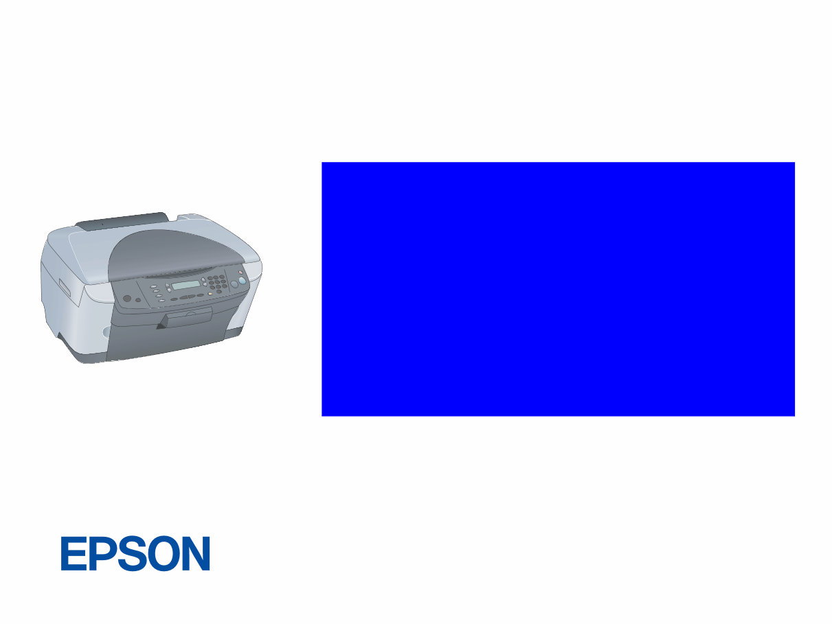
EPSON Stylus PHOTO RX500/510
Scanner • Printer • Copier
SERVICE MANUAL
SEOT03007
Download Service Manual And Resetter Printer at http://printer1.blogspot.com

Notice:
All rights reserved. No part of this manual may be reproduced, stored in a retrieval system, or transmitted in any form or by any means, electronic,
mechanical, photocopying, recording, or otherwise, without the prior written permission of SEIKO EPSON CORPORATION.
The contents of this manual are subject to change without notice.
All effort have been made to ensure the accuracy of the contents of this manual. However, should any errors be detected, SEIKO EPSON would greatly
appreciate being informed of them.
The above not withstanding SEIKO EPSON CORPORATION can assume no responsibility for any errors in this manual or the consequences thereof.
EPSON is a registered trademark of SEIKO EPSON CORPORATION.
General Notice: Other product names used herein are for identification purpose only and may be trademarks or registered trademarks of their
respective owners. EPSON disclaims any and all rights in those marks.
Copyright © 2003 SEIKO EPSON CORPORATION.
I&I CS Quality Promotion Dept.
(Printer Technical Support Grp.)
Imaging & Information Products Div.
Download Service Manual And Resetter Printer at http://printer1.blogspot.com

PRECAUTIONS
Precautionary notations throughout the text are categorized relative to 1)Personal injury and 2) damage to equipment.
DANGER Signals a precaution which, if ignored, could result in serious or fatal personal injury. Great caution should be exercised in
performing procedures preceded by DANGER Headings.
WARNING Signals a precaution which, if ignored, could result in damage to equipment.
The precautionary measures itemized below should always be observed when performing repair/maintenance procedures.
DANGER
1. ALWAYS DISCONNECT THE PRODUCT FROM THE POWER SOURCE AND PERIPHERAL DEVICES PERFORMING ANY MAINTENANCE
OR REPAIR PROCEDURES.
2. NO WORK SHOULD BE PERFORMED ON THE UNIT BY PERSONS UNFAMILIAR WITH BASIC SAFETY MEASURES AS DICTATED FOR
ALL ELECTRONICS TECHNICIANS IN THEIR LINE OF WORK.
3. WHEN PERFORMING TESTING AS DICTATED WITHIN THIS MANUAL, DO NOT CONNECT THE UNIT TO A POWER SOURCE UNTIL
INSTRUCTED TO DO SO. WHEN THE POWER SUPPLY CABLE MUST BE CONNECTED, USE EXTREME CAUTION IN WORKING ON
POWER SUPPLY AND OTHER ELECTRONIC COMPONENTS.
WARNING
1. REPAIRS ON EPSON PRODUCT SHOULD BE PERFORMED ONLY BY AN EPSON CERTIFIED REPAIR TECHNICIAN.
2. MAKE CERTAIN THAT THE SOURCE VOLTAGES IS THE SAME AS THE RATED VOLTAGE, LISTED ON THE SERIAL NUMBER/RATING
PLATE. IF THE EPSON PRODUCT HAS A PRIMARY AC RATING DIFFERENT FROM AVAILABLE POWER SOURCE, DO NOT CONNECT IT
TO THE POWER SOURCE.
3. ALWAYS VERIFY THAT THE EPSON PRODUCT HAS BEEN DISCONNECTED FROM THE POWER SOURCE BEFORE REMOVING OR
REPLACING PRINTED CIRCUIT BOARDS AND/OR INDIVIDUAL CHIPS.
4. IN ORDER TO PROTECT SENSITIVE MICROPROCESSORS AND CIRCUITRY, USE STATIC DISCHARGE EQUIPMENT, SUCH AS ANTI-
STATIC WRIST STRAPS, WHEN ACCESSING INTERNAL COMPONENTS.
5. REPLACE MALFUNCTIONING COMPONENTS ONLY WITH THOSE COMPONENTS BY THE MANUFACTURE; INTRODUCTION OF
SECOND-SOURCE ICs OR OTHER NON-APPROVED COMPONENTS MAY DAMAGE THE PRODUCT AND VOID ANY APPLICABLE EPSON
WARRANTY.
Download Service Manual And Resetter Printer at http://printer1.blogspot.com

About This Manual
This manual describes basic functions, theory of electrical and mechanical operations, maintenance and repair procedures of the printer. The instructions and procedures included
herein are intended for the experienced repair technicians, and attention should be given to the precautions on the preceding page.
Manual Configuration
This manual consists of six chapters and Appendix.
CHAPTER 1.PRODUCT DESCRIPTIONS
Provides a general overview and specifications of the product.
CHAPTER 2.OPERATING PRINCIPLES
Describes the theory of electrical and mechanical operations of
the product.
CHAPTER 3.TROUBLESHOOTING
Describes the step-by-step procedures for the troubleshooting.
CHAPTER 4.DISASSEMBLY / ASSEMBLY
Describes the step-by-step procedures for disassembling and
assembling the product.
CHAPTER 5.ADJUSTMENT
Provides Epson-approved methods for adjustment.
CHAPTER 6.MAINTENANCE
Provides preventive maintenance procedures and the lists of
Epson-approved lubricants and adhesives required for servicing
the product.
APPENDIX Provides the following additional information for reference:
• Connector pin assignments
• Electric circuit boards components layout
• Electrical circuit boards schematics
• Exploded diagram & Parts List
Symbols Used in this Manual
Various symbols are used throughout this manual either to provide additional
information on a specific topic or to warn of possible danger present during a
procedure or an action. Be aware of all symbols when they are used, and
always read NOTE, CAUTION, or WARNING messages.
Indicates an operating or maintenance procedure, practice or
condition that is necessary to keep the product’s quality.
Indicates an operating or maintenance procedure, practice, or
condition that, if not strictly observed, could result in damage to,
or destruction of, equipment.
May indicate an operating or maintenance procedure, practice or
condition that is necessary to accomplish a task efficiently. It may
also provide additional information that is related to a specific
subject, or comment on the results achieved through a previous
action.
Indicates an operating or maintenance procedure, practice or
condition that, if not strictly observed, could result in injury or loss
of life.
Indicates that a particular task must be carried out according to a
certain standard after disassembly and before re-assembly,
otherwise the quality of the components in question may be
adversely affected.
A D J U S T M E N T
R E Q U I R E D
C A U T I O N
C H E C K
P O I N T
W A R N I N G
Download Service Manual And Resetter Printer at http://printer1.blogspot.com

Revision Status
Revision Date of Issue Description
A September 16, 2003 First release
B February 2, 2004 CHAPTER 1 PRODUCT DESCRIPTION
• Outside Drawing is added to 1.2.7 Weight and Overall Dimensions (p.11).
CHAPTER 2 OPERATING PRINCIPLES
• 2.2.1.2 Printerhead Specification (p.15) is added.
• 2.2.1.3 Paper Feeding Motor Specification (p.15) is added.
• 2.2.1.4 PW Detector Specification (p.15) is added.
• Figure 2-3. Scanner Mechanism (p.16) is altered.
CHAPTER 3 TROUBLESHOOTING
• 3.3 Troubleshooting for Printer / Faulty paper ejection (p.30) is modified.
• 3.4 Troubleshooting for Scanner / Carriage unit does not operate (p.33) is modified.
• 3.4 Troubleshooting for Scanner / Fluorescent lamp does not turn on (p.33) is modified.
• 3.6 Troubleshooting for Motors and Sensors (p.35) is modified.
CHAPTER 4 DISASSEMBLY AND ASSEMBLY
• 4.1.5 Stylus PHOTO RX500/510 Disassembly (p.40) is modified.
• 4.5 Disassembly and Assembly of Printer Unit (p.49) is modified.
• 4.5.3 Printhead (p.53) is added.
• 4.5.7 Front Frame Assembly (p.57) is added.
• 4.5.8 Front Paper Guide (p.57) is added.
• 4.5.9 Waste Liquid Pad (p.58) is added.
CHAPTER 5 ADJUSTMENT
• 5.1 Overview (p.63) is altered.
• 5.2 Adjustments by Adjustment Program (p.65) is added.
• 5.3 Firmware Uploading (p.78) is modified.
CHAPTER 6 MAINTENANCE
• 6.1.1 Maintenance of the Printer (p.80) is modified.
CHAPTER 7 APPENDIX
• 7.1 Connectors / 7.1.1 Connector Assignments (p.86) is modified.
• 7.1 Connectors / Figure 7-1 Connector Assignments of Circuit Boards (p.86) is modified.
• A figure is added to 7.3 Exploded Diagrams (p.94).
• A list is added to 7.4 ASP List (p.101).
C September 24. 2004 Revision of 5.3 Firmware Uploading (p.78)
Download Service Manual And Resetter Printer at http://printer1.blogspot.com

EPSON Stylus PHOTO RX500/510 Revision B
6
CONTENTS
Chapter 1 Product Description
1.1 Overview .............................................................................................................. 9
1.1.1 Basic Functions ........................................................................................... 9
1.2 Common ............................................................................................................ 10
1.2.1 Electrical Specifications ........................................................................... 10
1.2.2 Interface .................................................................................................... 10
1.2.3 Conformance with Safety and EMC Standards ........................................ 10
1.2.4 Environmental Conditions ........................................................................ 11
1.2.5 Reliability ................................................................................................. 11
1.2.6 Acoustic Noise .......................................................................................... 11
1.2.7 Weight and Overall Dimensions ............................................................... 11
1.3 Ink Cartridge .................................................................................................... 12
Chapter 2 Operating Principles
2.1 Overview ............................................................................................................ 14
2.2 Mechanism ........................................................................................................ 14
2.2.1 Printer Mechanism .................................................................................... 14
2.2.1.1 Carriage Motor Specification ............................................................ 15
2.2.1.2 Printerhead Specification .................................................................. 15
2.2.1.3 Paper Feeding Motor Specification ................................................... 15
2.2.1.4 PW Detector Specification ................................................................ 15
2.2.2 Scanner Mechanism .................................................................................. 16
2.3 Electric Circuit .................................................................................................. 17
2.3.1 C544 Main Circuit Board ......................................................................... 18
2.3.1.1 Feature ............................................................................................... 18
Chapter 3 Troubleshooting
3.1 Overview ............................................................................................................ 20
3.1.1 Specified Tools ......................................................................................... 20
3.1.2 Preliminary Checks ................................................................................... 20
3.2 Troubleshooting at Unit Level ......................................................................... 21
3.2.1 Printer / Scanner does not operate at all
even with power turned on ........................................................................ 22
3.2.2 Error is detected ........................................................................................ 23
3.2.3 Trouble related to Print ............................................................................. 23
3.2.4 Paper feeding is not normally carried out ................................................. 24
3.2.5 Operation Panel faulty .............................................................................. 24
3.3 Troubleshooting for Printer ............................................................................ 25
3.4 Troubleshooting for Scanner ........................................................................... 32
3.5 I/F Concerned Troubleshooting ...................................................................... 34
3.6 Troubleshooting for Motors and Sensors ................................................ 35
Chapter 4 Disassembly and Assembly
4.1 Overview ............................................................................................................ 37
4.1.1 Precautions ................................................................................................ 37
4.1.2 Tools ......................................................................................................... 38
4.1.3 Screws ....................................................................................................... 38
4.1.4 Service Dispatch Standard ........................................................................ 39
4.1.5 Stylus PHOTO RX500/510 Disassembly ................................................. 40
4.2 Main Unit Removal .......................................................................................... 41
4.2.1 Panel Unit Removal .................................................................................. 41
4.2.2 Scanner Unit Removal .............................................................................. 42
4.2.3 Middle Housing Removal ......................................................................... 43
4.3 Disassembly and Assembly of Panel Unit ....................................................... 45
4.3.1 Panel Circuit Board Removal ................................................................... 45
4.4 Disassembly and Assembly of Scanner Unit .................................................. 46
4.4.1 Upper Housing Assembly Removal ......................................................... 47
4.4.2 CCD Module ............................................................................................. 48
4.4.3 Motor Assembly ...................................................................................... 48

EPSON Stylus PHOTO RX500/510 Revision B
7
4.4.4 HP Sensor Circuit Board .......................................................................... 48
4.5 Disassembly and Assembly of Printer Unit .................................................... 49
4.5.1 CR Scale ................................................................................................... 50
4.5.2 Carriage Unit ............................................................................................ 51
4.5.3 Printhead ................................................................................................... 53
4.5.4 ASF Unit Removal ................................................................................... 54
4.5.5 Disassembly of ASF Unit ......................................................................... 55
4.5.6 Power Unit ................................................................................................ 56
4.5.7 Front Frame Assembly ............................................................................. 57
4.5.8 Front Paper Guide ..................................................................................... 57
4.5.9 Waste Liquid Pad ...................................................................................... 58
4.6 Disassembly and Assembly of Other Parts .................................................... 59
4.6.1 Damper Assembly .................................................................................... 59
4.6.2 Stacker ...................................................................................................... 59
4.6.3 Main Board Unit ....................................................................................... 60
Chapter 5 Adjustment
5.1 Overview ............................................................................................................ 63
5.1.1 Adjustment Items for Individual Units and Components ......................... 64
5.2 Adjustments by Adjustment Program ............................................................ 65
5.2.1 Overview ................................................................................................... 65
5.2.1.1 Installing the Adjustment Program .................................................... 65
5.2.1.2 Starting the Adjustment Program ...................................................... 65
5.2.2 Adjustment ................................................................................................ 66
5.2.2.1 Market Setting (EEPROM initialization) .......................................... 66
5.2.2.2 USB ID Input ..................................................................................... 67
5.2.2.3 Head ID Input .................................................................................... 68
5.2.2.4 Head Angular Adjustment ................................................................. 68
5.2.2.5 1st Dot Position Adjustment .............................................................. 69
5.2.2.6 Bi-D Adjustment ............................................................................... 70
5.2.2.7 PW Adjustment ................................................................................. 71
5.2.2.8 Calorific Limitation Input ................................................................. 72
5.2.3 Maintenance .............................................................................................. 73
5.2.3.1 Head cleaning .................................................................................... 73
5.2.3.2 Ink charge .......................................................................................... 73
5.2.3.3 Refurbishment For DOA ................................................................... 74
5.2.3.4 Waste ink pad counter ....................................................................... 74
5.2.3.5 EEPROM data copy .......................................................................... 75
5.2.4 Check Pattern print ................................................................................... 76
5.2.4.1 Normal Paper Pattern ........................................................................ 76
5.2.4.2 Photo Quality Paper Pattern .............................................................. 76
5.2.4.3 Nozzle check pattern ......................................................................... 76
5.2.5 Appendix .................................................................................................. 77
5.2.5.1 Save all of EEPROM data ................................................................. 77
5.3 Firmware Uploading ........................................................................................ 78
5.3.1 Firmware Program File ............................................................................. 78
5.3.2 Firmware Update Procedure ..................................................................... 78
5.3.3 Update Error List ...................................................................................... 78
Chapter 6 Maintenance
6.1 Overview ............................................................................................................ 80
6.1.1 Maintenance of the Printer ....................................................................... 80
6.2 Cleaning ............................................................................................................. 80
6.3 Lubrication ........................................................................................................ 81
6.3.1 Designated Lubricant ................................................................................ 81
6.3.2 Lubrication Points of the Scanner ............................................................ 81
6.3.3 Lubrication Points of the Printer .............................................................. 82
Chapter 7 Appendix
7.1 Connectors ........................................................................................................ 86
7.1.1 Connector Assignments ............................................................................ 86
7.2 Electric Circuit Diagrams ................................................................................ 87
7.3 Exploded Diagrams .......................................................................................... 94
7.4 ASP List ........................................................................................................... 101

CHAPTER
1
PRODUCT DESCRIPTION
Download Service Manual And Resetter Printer at http://printer1.blogspot.com
EPSON Stylus PHOTO RX500/510 Revision C
Product Description Overview 9
1.1 Overview
This section describes the specifications for the SPC (Scanner, Printer, Copier)
machine “Stylus PHOTO RX500/510”.
1.1.1 Basic Functions
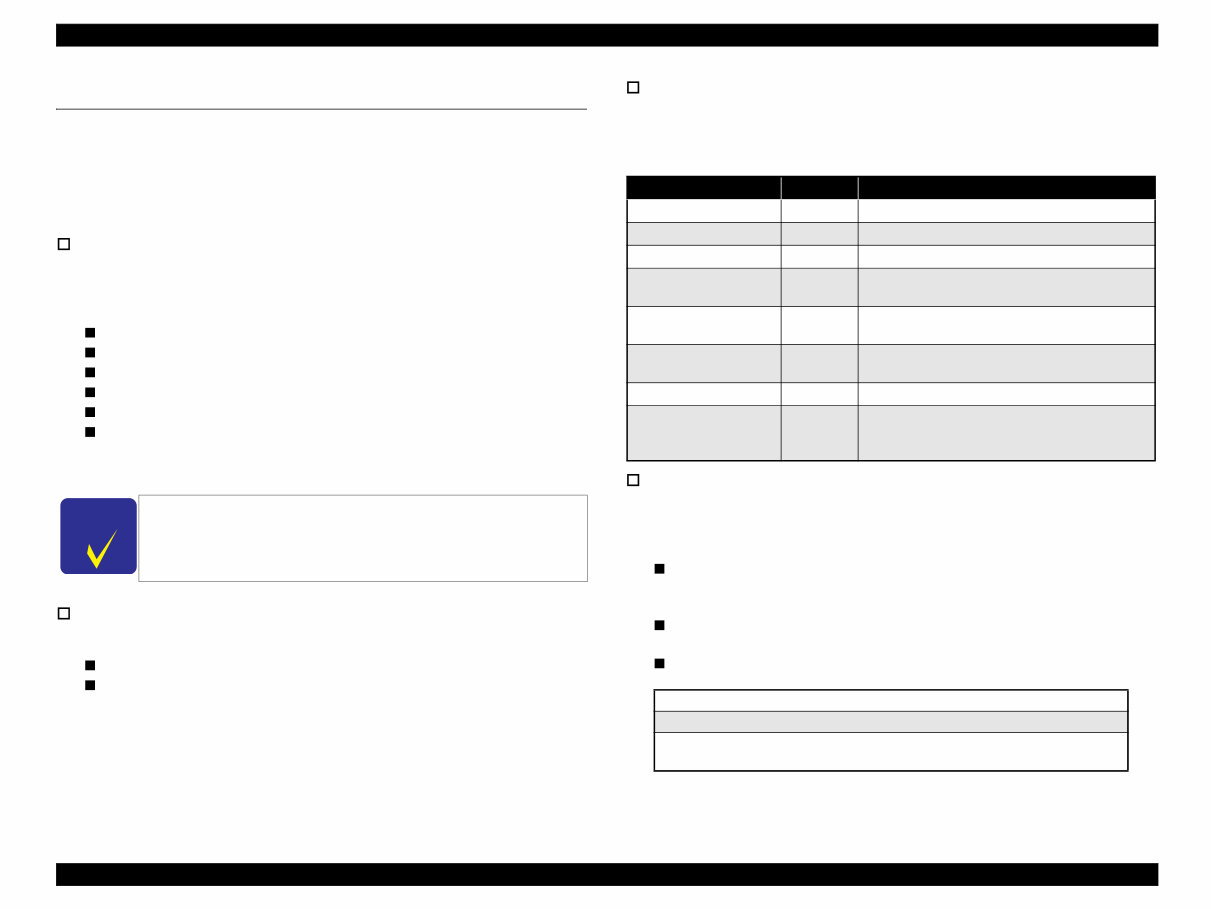
The functions of Stylus PHOTO RX500/510 are as described below:
Printer function
High quality and high speed printing, improved durability against lights, water,
gas and rubbing on regular copy paper due to introduction of new dye ink, and has
following features:
Maximum printing resolution: 2880 (H) x 1440 (V) dpi
Six color independent ink cartridge
BorderFree print on Epson special paper
Low noise
Alarms to prevent paper jam when stacker (output tray) is closed
Print head
Black Ink : 90 nozzles
Color Ink : 90 nozzles x 5 colors (C, M, Y, LC, LM)
Scanner function
The image can be easily acquired in the PC. Other features are as follows:
The maximum optical resolution :2400 x 4800dpi
Reading gradations :16bit (Input) /1bit, 8bit, 16bit (Output)
Standalone Copier function
The latest six color dye type printer engine allows to make photo quality copies on
the Epson special coated paper.
Other features are as follows:
Print Function with Memory Card
Stylus PHOTO RX500/510 is equipped with built-in memory card slot, and print
function with memory card at standalone.
Other features are as follows:
Supports index sheet print that allows you to simply select images by marking
on index sheet. Simplifies image selection by scanning or checking the
marking sheet.
Ten key allows you to select single image and print range, or all images and
all range print.
Compatible to various memory cards.
Note “*”: Adapter required
C H E C K
P O I N T
Ink cartridge is not compatible to previous model, Stylus CX3100/
3200.
Refer to “ 1.3 Ink Cartridge (p12)”.
Copy Mode Margin Feature
Standard copy
3mm Normal copy
BorderFree copy
N/A Full copy with no margin
Small margin copy
1.5mm Margins are 1.5 mm in four sides
Repeat copy
-
Copies original size on multiple places in the media
(4/8/16).
Poster copy
-
Divides the original image into 4/8/16, and produces
poster size copy (A4 and Letter size only).
2-up/4 up copy
-
Reduces 2 pages/4 pages of the original image to
single page.
Mirror copy
- Flips over the original left to right.
Wallet size photo copy
(Only for EAI)
-
Adjusts image to wallet size (3.5” x 2.5”), and
places (For EAI only) multiple images in single
page (A4 and Letter size only)
Compact Flash / Microdrive
Smart Media / xD-Picture Card
Memory Stick / MagicGate Memory Stick / Memory Stick PRO /
Memory Stick Duo* / SD Memory Card / miniSD Card* /MultiMediaCard
EPSON Stylus PHOTO RX500/510 Revision C
Product Description Common 10
1.2 Common
The specifications described below are common to the scanner and printer.
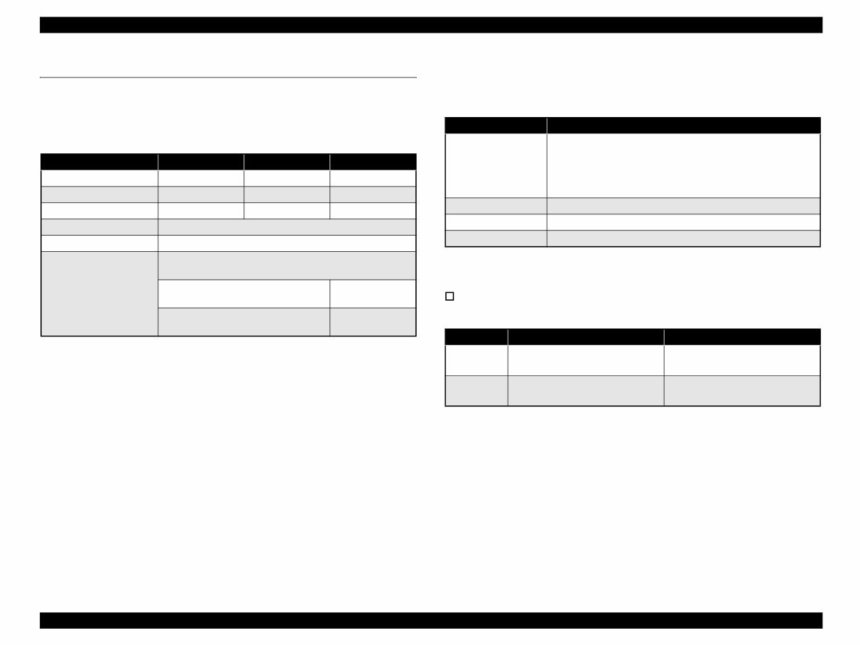
1.2.1 Electrical Specifications
Note 1: The product is Energy Star compliant.
2: The holding current to the motors is reduced when the printer has stayed in non-
operation status for 5 minutes.
3: The Scanner lamp is turned off when the Scanner has stayed in nonoperation status for
15 minutes.
1.2.2 Interface
USB 2.0 compatible. See Table 1-2. for details.
1.2.3 Conformance with Safety and EMC Standards
Conformance with EMC standard
Table 1-1. AC Input
100V model 120V model 220-240V model
Rated voltage (ACV) 100 120 220-240
Input voltage (ACV) 90-110 108-132 198-240
Rated current (A) 0.8A 0.8A 0.4A
Rated frequency range (Hz) 50 ~ 60
Input frequency range (Hz) 49.5 ~ 60.5
Power consumption (W)
Approx. 21 W (Standalone copying, ISO10561 Letter Patter,
Plain Paper - Text)
Approx. 4 W (Sleep Mode)
Approx. 4 W
(Sleep Mode)
Approx. 0.4 W (Power Off Mode)
Approx. 0.5 W
(Power Off Mode)
Table 1-2.
Item Descriptions
Standard “Universal Serial Bus Specifications Revision 2.0”
“Universal Serial Bus Device Class Definition for Printing Devices
Version 1.1” (printer unit)
“Universal Serial Bus Mass Storage Class Bulk-Only Transport
Revision 1.0”(storage unit)
Data transfer speed 480Mbps (High Speed Device)
Data format NRZI
Conforming connecter USB Series B
Table 1-3.
120 V version 220-240 V version
Safety
• UL1950
• CSA 22.2 No.950
• EN 60950(VDE)
EMI
• FCC part15 subpart B class B
• CSA C108.8 class B
• EN 55022 (CISPR Pub.22) class B
• AS/NZS 3548 class B
You're Reading a Preview
What's Included?
 Lifetime Access
Fast Download Speeds
Online & Offline Access
Access PDF Contents & Bookmarks
Full Search Facility
Print one or all pages of your manual
$27.99
Epson Stylus Photo Rx500 Rx510 Service Manual
Viewed 47 Times Today

What's Included?
Lifetime Access
Fast Download Speeds
Online & Offline Access
Access PDF Contents & Bookmarks
Full Search Facility
Print one or all pages of your manual
$27.99

Secure transaction
What's Included?
Lifetime Access
Fast Download Speeds
Online & Offline Access
Access PDF Contents & Bookmarks
Full Search Facility
Print one or all pages of your manual
Description
Discover a comprehensive workshop manual from the Service Manual Shop, designed to assist in the repair and maintenance of Epson Stylus Photo RX500 RX510 printers. This manual is invaluable for professional mechanics and DIY enthusiasts alike, providing detailed fault diagnosis, troubleshooting guides, technical circuit diagrams, and exploded assembly figures. Whether it's for repair, maintenance, dismantling, or reassembly, this manual covers all aspects to help you resolve any issues with your printer. Available in a convenient format for quick and easy access.
- Useful for professional mechanics and DIY enthusiasts
- Covers repair, maintenance, dismantling, and reassembly
- Detailed fault diagnosis and troubleshooting guides
- Includes technical circuit diagrams and exploded assembly figures
Page: 78


