PRECAUTIONS Precautionary notations throughout the text are categorized relative to 1) Personal injury and 2) damage to equipment. DANGER Signals a precaution which, if ignored, could result in serious or fatal personal injury. Great caution should be exercised in performing procedures preceded by DANGER Headings. WARNING Signals a precaution which, if ignored, could result in damage to equipment. The precautionary measures itemized below should always be observed when performing repair/maintenance procedures. DANGER 1. ALWAYS DISCONNECT THE PRODUCT FROM THE POWER SOURCE AND PERIPHERAL DEVICES PERFORMING ANY MAINTENANCE OR REPAIR PROCEDURES. 2. NO WORK SHOULD BE PERFORMED ON THE UNIT BY PERSONS UNFAMILIAR WITH BASIC SAFETY MEASURES AS DICTATED FOR ALL ELECTRONICS TECHNICIANS IN THEIR LINE OF WORK. 3. WHEN PERFORMING TESTING AS DICTATED WITHIN THIS MANUAL, DO NOT CONNECT THE UNIT TO A POWER SOURCE UNTIL INSTRUCTED TO DO SO. WHEN THE POWER SUPPLY CABLE MUST BE CONNECTED, USE EXTREME CAUTION IN WORKING ON POWER SUPPLY AND OTHER ELECTRONIC COMPONENTS. 4. WHEN DISASSEMBLING OR ASSEMBLING A PRODUCT, MAKE SURE TO WEAR GLOVES TO AVOID INJURIER FROM METAL PARTS WITH SHARP EDGES. WARNING 1. REPAIRS ON EPSON PRODUCT SHOULD BE PERFORMED ONLY BY AN EPSON CERTIFIED REPAIR TECHNICIAN. 2. MAKE CERTAIN THAT THE SOURCE VOLTAGES IS THE SAME AS THE RATED VOLTAGE, LISTED ON THE SERIAL NUMBER/RATING PLATE. IF THE EPSON PRODUCT HAS A PRIMARY AC RATING DIFFERENT FROM AVAILABLE POWER SOURCE, DO NOT CONNECT IT TO THE POWER SOURCE. 3. ALWAYS VERIFY THAT THE EPSON PRODUCT HAS BEEN DISCONNECTED FROM THE POWER SOURCE BEFORE REMOVING OR REPLACING PRINTED CIRCUIT BOARDS AND/OR INDIVIDUAL CHIPS. 4. IN ORDER TO PROTECT SENSITIVE MICROPROCESSORS AND CIRCUITRY, USE STATIC DISCHARGE EQUIPMENT, SUCH AS ANTI-STATIC WRIST STRAPS, WHEN ACCESSING INTERNAL COMPONENTS. 5. DO NOT REPLACE IMPERFECTLY FUNCTIONING COMPONENTS WITH COMPONENTS WHICH ARE NOT MANUFACTURED BY EPSON. IF SECOND SOURCE IC OR OTHER COMPONENTS WHICH HAVE NOT BEEN APPROVED ARE USED, THEY COULD CAUSE DAMAGE TO THE EPSON PRODUCT, OR COULD VOID THE WARRANTY OFFERED BY EPSON.
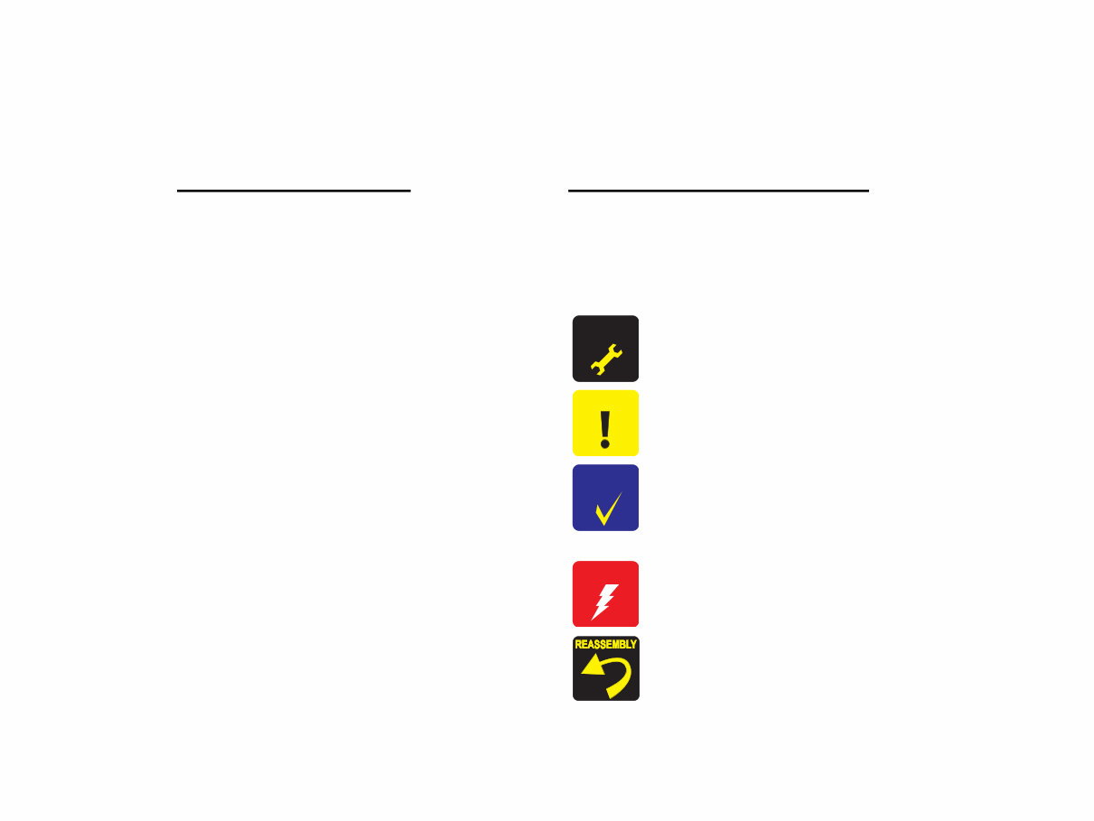
About This Manual This manual describes basic functions, theory of electrical and mechanical operations, maintenance and repair procedures of the printer. The instructions and procedures included herein are intended for the experienced repair technicians, and attention should be given to the precautions on the preceding page. Manual Configuration This manual consists of six chapters and Appendix. CHAPTER 1. TROUBLESHOOTING Describes the step-by-step procedures for the troubleshooting. CHAPTER 2. DISASSEMBLY / ASSEMBLY Describes the step-by-step procedures for disassembling and assembling the product. CHAPTER 3. ADJUSTMENT Provides Epson-approved methods for adjustment. CHAPTER 4. MAINTENANCE Provides preventive maintenance procedures and the lists of Epson-approved lubricants and adhesives required for servicing the product. APPENDIX Provides the following additional information for reference: • Electrical circuit boards schematics Symbols Used in this Manual Various symbols are used throughout this manual either to provide additional information on a specific topic or to warn of possible danger present during a procedure or an action. Be aware of all symbols when they are used, and always read NOTE, CAUTION, or WARNING messages. Indicates an operating or maintenance procedure, practice or condition that is necessary to keep the product’s quality. Indicates an operating or maintenance procedure, practice, or condition that, if not strictly observed, could result in damage to, or destruction of, equipment. May indicate an operating or maintenance procedure, practice or condition that is necessary to accomplish a task efficiently. It may also provide additional information that is related to a specific subject, or comment on the results achieved through a previous action. Indicates an operating or maintenance procedure, practice or condition that, if not strictly observed, could result in injury or loss of life. Indicates that a particular task must be carried out according to a certain standard after disassembly and before re-assembly, otherwise the quality of the components in question may be adversely affected. A D J U S T M E N T R E Q U I R E D C A U T I O N C H E C K P O I N T W A R N I N G
Revision Status Revision Issued Date Description A October 30, 2003 First Release
CONTENTS Chapter 1 TROUBLESHOOTING 1.1 Overview .............................................................................................................. 8 1.2 Troubleshooting with LED/LCD Indications and Status Monitor 3 Message ..... 9 1.3 Unit Level Troubleshooting ............................................................................... 14 Chapter 2 DISASSEMBLY AND ASSEMBLY 2.1 Overview ............................................................................................................ 32 2.1.1 Precautions ................................................................................................. 32 2.1.2 Tools .......................................................................................................... 33 2.1.3 Pre-Shipment Checks ................................................................................. 33 2.2 Caution regarding assembling/disassembling the printer mechanism, and how to ensure the quality of reassembled product ............................................................... 35 2.3 Disassembly ........................................................................................................ 37 2.3.1 Removing Paper Support Assy. ................................................................. 38 2.3.2 Removing Housing, Upper ........................................................................ 39 2.3.3 Removing Housing, Middle ....................................................................... 41 2.3.4 Removing Porous Pad, Paper Guide, Front ............................................... 43 2.3.5 Removing Panel Board .............................................................................. 44 2.3.6 Removing Stacker Assy. ............................................................................ 45 2.3.7 Removing Main Board .............................................................................. 46 2.3.8 Removing ASF Assy. ................................................................................ 49 2.3.9 Removing Holder, Shaft Assy. .................................................................. 51 2.3.10 Removing CR Motor ............................................................................... 54 2.3.11 Removing APG Assy. .............................................................................. 55 2.3.12 Removing Print Head .............................................................................. 56 2.3.13 Removing Carriage Unit .......................................................................... 57 2.3.14 Removing Paper Guide, Upper ................................................................ 63 2.3.15 Removing Printer Mechanism/Housing, Lower ...................................... 64 2.3.16 Removing Power Supply Unit ................................................................. 68 2.3.17 Removing CDR Guide Assy. ................................................................... 69 2.3.18 Removing Ink System .............................................................................. 71 2.3.19 Removing Paper Guide, Front/Roller EJ Assy. ....................................... 74 2.3.20 Removing PF Motor ................................................................................ 78 Chapter 3 ADJUSTMENT 3.1 Adjustment Items and Overview ........................................................................ 80 3.1.1 Servicing Adjustment Item List ................................................................. 80 3.1.2 Replacement Part-Based Adjustment Priorities ........................................ 83 3.2 Adjustment by using adjustment program .......................................................... 85 3.2.1 Market Setting ........................................................................................... 85 3.2.2 USB ID Input ............................................................................................. 85 3.2.3 Head ID Input ............................................................................................ 85 3.2.4 Head Angular Adjustment ......................................................................... 86 3.2.5 Bi-d Adjustment ........................................................................................ 86 3.2.6 PW Sensor Adjustment .............................................................................. 87 3.2.7 First Dot Adjustment ................................................................................. 87 3.2.8 Offset Input for CR Motor Calorific Limitation ........................................ 88 3.2.9 A4 Normal Paper Print .............................................................................. 88 3.2.10 A4 Photo Quality Inkjet Paper Print ........................................................ 88 3.2.11 A4 Photo Paper/ Glossy Photo Paper print .............................................. 88 3.3 Adjustment Except Adjustment Program ........................................................... 89 3.3.1 PG Adjustment .......................................................................................... 89 Chapter 4 MAINTENANCE 4.1 Overview ............................................................................................................ 93 4.1.1 Cleaning ..................................................................................................... 93 4.1.2 Service Maintenance .................................................................................. 93 4.1.3 Lubrication ................................................................................................. 95 Chapter 5 APPENDIX 5.1 Exploded Diagram ............................................................................................ 103 5.2 Electrical Circuits ............................................................................................. 103
CHAPTER 1 TROUBLESHOOTING
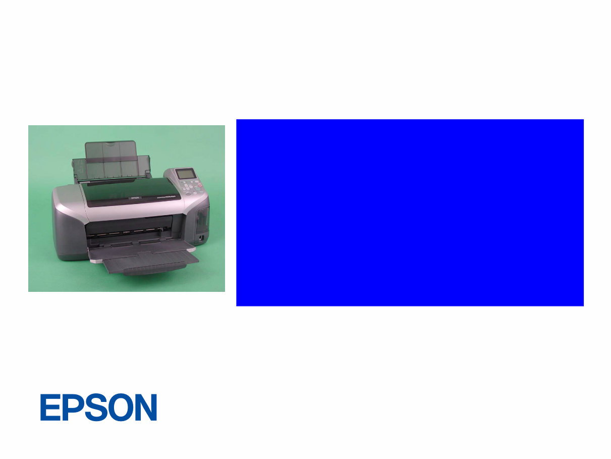
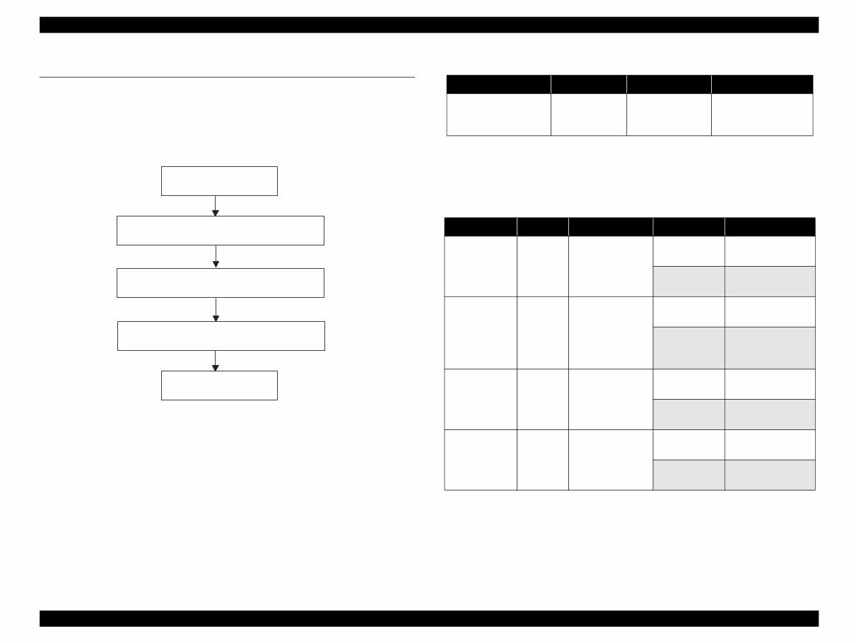
EPSON Stylus Photo R300/R310 Revision A TROUBLESHOOTING Overview 8 1.1 Overview This chapter describes how to identify troubles in two levels: unit level repair and component level repair. Refer to the flowchart in this chapter to identify the defective unit and perform component level repair if necessary. This chapter also explains motor coil resistance, Sensor specification and error indication. Figure 1-1. Troubleshooting Flowchart Since "CR Motor" and APG Motor are DC motors, the resistance among the electric poles varies. Therefore, judge if it is normal or abnormal based on if there is operation of the motor or not; the resistance values cannot be used to judge the abnormality. However, it is difficult to judge accurately, if it is not clear, replace the motor. START UNIT-LEVEL TROUBLESHOOTING UNIT REPAIR ASSEMBLY AND ADJUSTMENT END Table 1-1. Motor, Coil Resistance Motor Location Check Point Resistance PF Motor (Same as ASF/ Pump Motor) CN9 Pin 1 and 3 Pin 2 and 4 3.0Ω ±10% (25°C/phase) Table 1-2. Sensor check point Sensor name Location Check point Signal level Switch mode PE Sensor CN4 Pin 1 and 2 More than 2.4V Off : No paper Less than 0.4V On : Detect paper PG Sensor CN5 Pin 1 and 2 More than 2.4V Off : Anywhere of PG Less than 0.4V On : In process of switching PG Star Wheel Sensor CN6 Pin 1 and 2 - On : ASF mode - Off : CDR mode CDR Sensor CN6 Pin 3 and 4 - Off : No CDR Tray - On : Detect CDR Tray
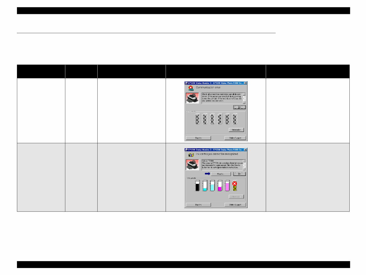
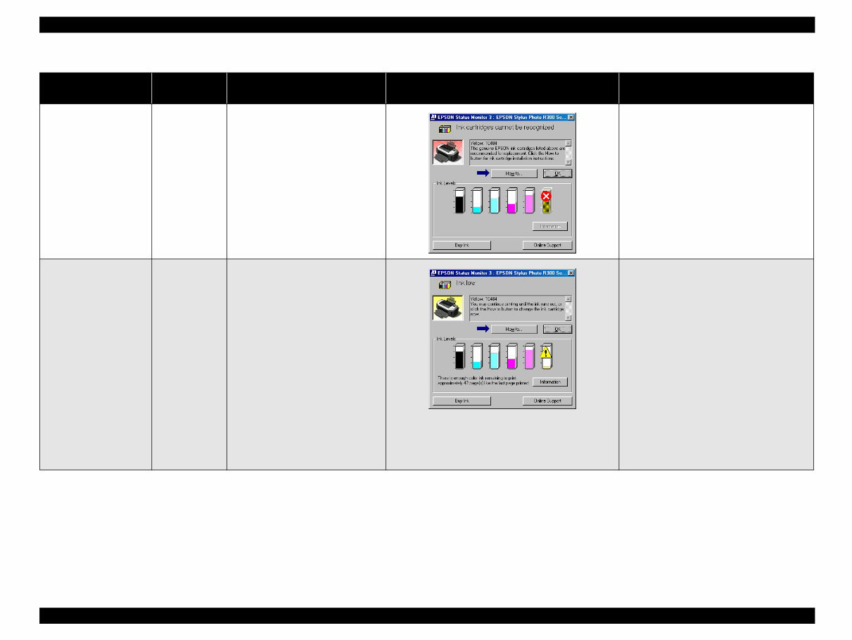
EPSON Stylus Photo R300/R310 Revision A TROUBLESHOOTING Troubleshooting with LED/LCD Indications and Status Monitor 3 Message 9 1.2 Troubleshooting with LED/LCD Indications and Status Monitor 3 Message This section describes the LED/LCD indication, the STM3 message and the error condition when the printer detects an error in each operation such as the power on, the paper loading/feeding and the ink absorption operation. Table 1-3. LED/LCD Indication and STM3 Printer status Maintenance LED indication LCD indication STM3 message Condition for error detection Communication Error -- -- This error is detected when the printer cannot communicate with the PC properly. Error before Initial Ink Charge Blink Ink Cartridge cannot be recognized. Yelolow: T0484 For best result, use genuine EPSON ink. This error is detected when a defective cartridge is installed in the printer which the Initial Ink Filling is not done yet.
EPSON Stylus Photo R300/R310 Revision A TROUBLESHOOTING Troubleshooting with LED/LCD Indications and Status Monitor 3 Message 10 Error before ink replacement Cleaning Blink Ink Cartridge cannot be recognized. Yellow: T0484 For best result, use genuine EPSON ink. This error is detected when replacing the Ink Cartridge, if the new cartridge is defective. Ink Low Condition Blink (Blink of Ink Cartridge Icon) Note : Printing operation can be performed until it becomes ink end condition even after the error message is displayed on STM3. However, the Head Cleaning operation may not be performed due to the Ink Low condition. This error is detected when the ink consumption reaches about 90%. (Note) When the Ink Low Condition is detected, the Maintenance LED will blink. The printer will continue to keep this LED status even if a new Ink Cartridge is installed in the Ink Cartridge replacement position. However, this LED status will be reset (LED off) when "Carriage Unit" returns to the home position. Table 1-3. LED/LCD Indication and STM3 Printer status Maintenance LED indication LCD indication STM3 message Condition for error detection
You're Reading a Preview
What's Included?
Lifetime Access
Fast Download Speeds
Online & Offline Access
Access PDF Contents & Bookmarks
Full Search Facility
Print one or all pages of your manual
$27.99
Epson Stylus Photo R300/R310 Color Inkjet Printer Service Repair Manual
This is the complete factory Service Repair Manual for the Epson Stylus Photo R300/R310 Color Inkjet Printer. This Service Manual contains easy-to-read text sections with high-quality diagrams and instructions, providing step-by-step guidance for repairing your EPSON machine.
These manuals are useful for both professional mechanics and DIY enthusiasts.
Models Covered:
Epson Stylus Photo R300 Color Inkjet Printer
Epson Stylus Photo R310 Color Inkjet Printer
This Manual Covers:
CHAPTER 1. TROUBLESHOOTING
CHAPTER 2. DISASSEMBLY / ASSEMBLY
CHAPTER 3. ADJUSTMENT
CHAPTER 4. MAINTENANCE
APPENDIX
Model Specification: Epson Stylus Photo R300/R310 Color Inkjet Printer
Total Pages: 108
Language: English
File Format: PDF
Requirements: Adobe Reader
Compatible: All Versions of Windows & Mac, APP ISO, Iphone, Ipad, Android etc...
This manual is in PDF format. The Service Manual is fully indexed and bookmarked by topic. This original Adobe document ensures perfect quality and printing. The PDF can be searched quickly to find what you need to know in every chapter. You can print the entire manual or select any pages you want. You can also zoom in on any diagram or picture to easily see every part.
Save time and money by doing your own repairs! This manual provides easy-to-follow, step-by-step instructions and pictures for all areas of repair.
All Service Repair Manuals are instant downloads, meaning no shipping cost or waiting for a CD or paper manual to arrive in the mail. You will receive this manual today via instant download on completion of payment via our secure payment processor. We accept all major credit/debit cards and PayPal.
Reviews
Q&A
Recently Viewed
5,521,897Happy Clients
2,594,462eManuals
1,120,453Trusted Sellers
15Years in Business
Price:
Actual Price:
Epson Stylus Photo R300/R310 Color Inkjet Printer Service Repair Manual







 Lifetime Access




