

EPSON Stylus Photo R1800/R2400
Color Inkjet Printer
SEIJ04015
SERVICE MANUAL
Download Service Manual And Resetter Printer at http://printer1.blogspot.com

Notice:
All rights reserved. No part of this manual may be reproduced, stored in a retrieval system, or transmitted in any form or by any means, electronic,
mechanical, photocopying, recording, or otherwise, without the prior written permission of SEIKO EPSON CORPORATION.
The contents of this manual are subject to change without notice.
All effort have been made to ensure the accuracy of the contents of this manual. However, should any errors be detected, SEIKO EPSON would greatly
appreciate being informed of them.
The above not withstanding SEIKO EPSON CORPORATION can assume no responsibility for any errors in this manual or the consequences thereof.
EPSON is a registered trademark of SEIKO EPSON CORPORATION.
General Notice: Other product names used herein are for identification purpose only and may be trademarks or registered trademarks of their
respective owners. EPSON disclaims any and all rights in those marks.
Copyright © 2005 SEIKO EPSON CORPORATION.
I&I CS/Quality Management & PL Department

PRECAUTIONS
Precautionary notations throughout the text are categorized relative to 1)Personal injury and 2) damage to equipment.
DANGER Signals a precaution which, if ignored, could result in serious or fatal personal injury. Great caution should be exercised in performing
procedures preceded by DANGER Headings.
WARNING Signals a precaution which, if ignored, could result in damage to equipment.
The precautionary measures itemized below should always be observed when performing repair/maintenance procedures.
DANGER
1. ALWAYS DISCONNECT THE PRODUCT FROM THE POWER SOURCE AND PERIPHERAL DEVICES PERFORMING ANY MAINTENANCE OR REPAIR
PROCEDURES.
2. NO WORK SHOULD BE PERFORMED ON THE UNIT BY PERSONS UNFAMILIAR WITH BASIC SAFETY MEASURES AS DICTATED FOR ALL
ELECTRONICS TECHNICIANS IN THEIR LINE OF WORK.
3. WHEN PERFORMING TESTING AS DICTATED WITHIN THIS MANUAL, DO NOT CONNECT THE UNIT TO A POWER SOURCE UNTIL INSTRUCTED TO
DO SO. WHEN THE POWER SUPPLY CABLE MUST BE CONNECTED, USE EXTREME CAUTION IN WORKING ON POWER SUPPLY AND OTHER
ELECTRONIC COMPONENTS.
WARNING
1. REPAIRS ON EPSON PRODUCT SHOULD BE PERFORMED ONLY BY AN EPSON CERTIFIED REPAIR TECHNICIAN.
2. MAKE CERTAIN THAT THE SOURCE VOLTAGES IS THE SAME AS THE RATED VOLTAGE, LISTED ON THE SERIAL NUMBER/RATING PLATE. IF THE
EPSON PRODUCT HAS A PRIMARY AC RATING DIFFERENT FROM AVAILABLE POWER SOURCE, DO NOT CONNECT IT TO THE POWER SOURCE.
3. ALWAYS VERIFY THAT THE EPSON PRODUCT HAS BEEN DISCONNECTED FROM THE POWER SOURCE BEFORE REMOVING OR REPLACING
PRINTED CIRCUIT BOARDS AND/OR INDIVIDUAL CHIPS.
4. IN ORDER TO PROTECT SENSITIVE MICROPROCESSORS AND CIRCUITRY, USE STATIC DISCHARGE EQUIPMENT, SUCH AS ANTI-STATIC WRIST
STRAPS, WHEN ACCESSING INTERNAL COMPONENTS.
5. REPLACE MALFUNCTIONING COMPONENTS ONLY WITH THOSE COMPONENTS BY THE MANUFACTURE; INTRODUCTION OF SECOND-SOURCE
ICs OR OTHER NON-APPROVED COMPONENTS MAY DAMAGE THE PRODUCT AND VOID ANY APPLICABLE EPSON WARRANTY.
About This Manual
This manual describes basic functions, theory of electrical and mechanical operations, maintenance and repair procedures of the printer. The instructions and
procedures included herein are intended for the experienced repair technicians, and attention should be given to the precautions on the preceding page.
Manual Configuration
This manual consists of six chapters and Appendix.
CHAPTER 1.PRODUCT DESCRIPTIONS
Provides a general overview and specifications of the product.
CHAPTER 2.OPERATING PRINCIPLES
Describes the theory of electrical and mechanical operations of
the product.
CHAPTER 3.TROUBLESHOOTING
Describes the step-by-step procedures for the troubleshooting.
CHAPTER 4.DISASSEMBLY / ASSEMBLY
Describes the step-by-step procedures for disassembling and
assembling the product.
CHAPTER 5.ADJUSTMENT
Provides Epson-approved methods for adjustment.
CHAPTER 6.MAINTENANCE
Provides preventive maintenance procedures and the lists of
Epson-approved lubricants and adhesives required for servicing
the product.
APPENDIX Provides the following additional information for reference:
• Connector pin assignments
• Exploded diagram & Parts List
• Electric circuit boards components layout
• Electrical circuit boards schematics
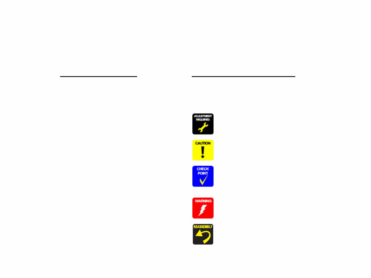
Symbols Used in this Manual
Various symbols are used throughout this manual either to provide additional
information on a specific topic or to warn of possible danger present during a
procedure or an action. Be aware of all symbols when they are used, and
always read NOTE, CAUTION, or WARNING messages.
Indicates an operating or maintenance procedure, practice or
condition that is necessary to keep the product’s quality.
Indicates an operating or maintenance procedure, practice, or
condition that, if not strictly observed, could result in damage to,
or destruction of, equipment.
May indicate an operating or maintenance procedure, practice or
condition that is necessary to accomplish a task efficiently. It may
also provide additional information that is related to a specific
subject, or comment on the results achieved through a previous
action.
Indicates an operating or maintenance procedure, practice or
condition that, if not strictly observed, could result in injury or loss
of life.
Indicates that a particular task must be carried out according to a
certain standard after disassembly and before re-assembly,
otherwise the quality of the components in question may be
adversely affected.

Revision Status
Revision Date of Issue Description
A January 21, 2005 First Release
B March 31, 2005 Revised Contents
8. Stylus Photo R2400 (p198)
• Stylus Photo specific information is added.
5.2.5.1 Printing Calibration Chart by Users (p165)
• Descriptions of the procedure are added.
5.2.5.2 Writing of Color ID by Users (p169)
• A caution is deleted.
Color Correction Value Entry Procedure (p170)
• Supported OS and ports are added.
Calibration Chart Print Procedure for Users (p166)
• Descriptions of the procedure are added.

EPSON Stylus Photo R1800/R2400 Revision B
6
CONTENTS
Chapter 1 Product Description
1.1 Overview.................................................................................................. 9
1.2 PG Setting ............................................................................................. 10
1.3 Functions .............................................................................................. 11
1.3.1 Control Panel ................................................................................ 11
1.3.2 Switches ........................................................................................ 11
1.3.3 Indicators ....................................................................................... 11
1.3.4 Switch Functions ........................................................................... 11
1.3.5 Indicator Display in Normal Mode ................................................. 12
1.3.6 Error Status ................................................................................... 13
1.4 Casing Specifications .......................................................................... 14
1.5 Accessories .......................................................................................... 14
Chapter 2 Operating Principles
2.1 Overview................................................................................................ 16
2.2 Printer Mechanism ............................................................................... 16
2.2.1 Carriage Mechanism ..................................................................... 17
2.2.2 Printhead Specifications ................................................................ 20
2.2.3 Paper Feeding Mechanism ........................................................... 20
2.2.4 Paper Feeding Mechanism ........................................................... 25
2.2.5 Ink System Mechanism ................................................................. 26
2.2.6 Ink Sequence ................................................................................ 28
2.2.7 Power-On Sequence ..................................................................... 30
2.3 Electrical Circuit Operating Principles ............................................... 31
2.3.1 Power Supply Circuit Operating Principle ..................................... 32
2.3.2 C589 MAIN Circuit Operating Principle ......................................... 33
Chapter 3 Troubleshooting
3.1 Overview................................................................................................ 36
3.1.1 Troubleshooting according to Panel Messages ............................ 36
3.1.2 Troubleshooting based on Observed Faults ................................. 59
Chapter 4 Disassembly And Assembly
4.1 Overview ............................................................................................... 69
4.1.1 Precautions ................................................................................... 69
4.1.2 Tools ............................................................................................. 70
4.1.3 Screws .......................................................................................... 71
4.1.4 Work Completion Checklist ........................................................... 72
4.2 Disassembly ......................................................................................... 73
4.2.1 Removing the Housings ................................................................ 74
4.2.2 Waste Ink Pad ............................................................................... 80
4.2.3 Front Paper Guide Pad ................................................................. 82
4.2.4 ASF Assy ...................................................................................... 83
4.2.5 Removing the Boards ................................................................... 87
4.2.6 Disassembling the Printer Mechanism .......................................... 89
4.2.7 Removing the Motors .................................................................. 122
4.2.8 Removing the Sensors ................................................................ 124
Chapter 5 Adjustment
5.1 Adjustment Items and Overview ....................................................... 129
5.1.1 Servicing Adjustment Item List .................................................... 129
5.1.2 Replacement Part-Based Adjustment Priorities .......................... 133
5.1.3 Required Adjustment Tools ......................................................... 136
5.2 Adjustment .......................................................................................... 137
5.2.1 PF Belt Tension Adjustment ....................................................... 137
5.2.2 PG Adjustment ............................................................................ 139
5.2.3 PF Roller Shaft Center Support Position Adjustment ................. 143
5.2.4 Colorimetric Calibration ............................................................... 147
5.2.5 Colorimetric Calibration by Users ............................................... 165
Chapter 6 Maintenance
6.1 Overview ............................................................................................. 173
6.1.1 ROM Replacement ..................................................................... 173
6.1.2 Cleaning ...................................................................................... 173
6.1.3 Service Maintenance .................................................................. 174

EPSON Stylus Photo R1800/R2400 Revision B
7
6.1.4 Lubrication ................................................................................... 175
Chapter 7 Appendix
7.1 Connector Summary .......................................................................... 182
7.1.1 Connectors and Pin Layouts ....................................................... 182
7.2 Exploded Diagram .............................................................................. 183
7.3 Parts List for EPSON Stylus Photo R1800 ....................................... 190
7.4 Circuit Diagram................................................................................... 192
Chapter 8 Stylus Photo R2400
8.1 Overview.............................................................................................. 199
8.1.1 Overview ..................................................................................... 199
8.1.2 Indicator Display in Normal Mode ............................................... 200
8.1.3 Error Status ................................................................................. 201
8.2 Casing Specifications ........................................................................ 202
8.3 Accessories ........................................................................................ 202
8.3.1 Printhead Specifications .............................................................. 203
8.3.2 Ink Sequence .............................................................................. 203
8.4 Overview.............................................................................................. 204
8.4.1 Troubleshooting according to Panel Messages .......................... 204
8.5 Parts List for EPSON Stylus Photo R2400 ....................................... 227

CHAPTER
1
PRODUCT DESCRIPTION
EPSON Stylus Photo R1800/R2400 Revision B
Product Description Overview 9
1.1 Overview
The Stylus Photo R1800 is a photo printer designed for a wide range of users
from individual users to commercial users. As a successor to the Stylus Photo
2100/2200, this consumer middle high model is capable of CD-R/DVD-R
printing and roll paper cutter functions.
This product has the following features.
FEATURES
High color print quality
5760 (H) x 1440 (V) dpi printing (Max resolution)
8 color printing
(PPI Black, Photo Black, Cyan, Magenta, Yellow, Red, Violet, Clear)
Pigment Ink supported
Separate Ink Cartridge for each color
Built-in 2 I/F
USB 2.0 (HS compatibility)
IEEE 1394
Windows/Macintosh exclusive
Roll Paper Support
Printable area expand (Bottom margin reduce)
Card printing support
CD-R printing support
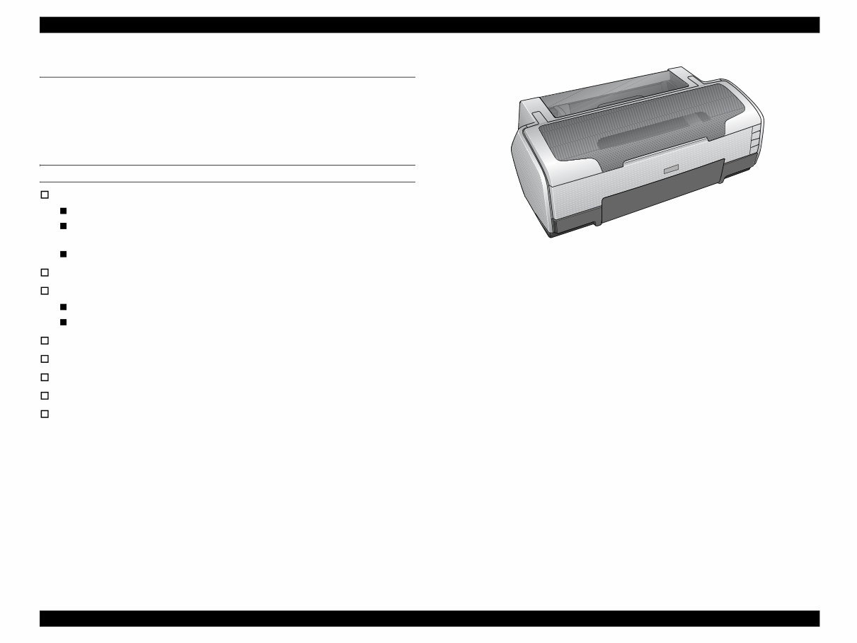
Figure 1-1. Product Appearance

EPSON Stylus Photo R1800/R2400 Revision B
Product Description PG Setting 10
1.2 PG Setting
As this printer uses an Auto PG (APG), an appropriate PG position is set according to the used paper type.
The following table indicates the PG positions, the main applications of each position, and the relationships between the two sensors used with the APG.
Table 1-1.
Application
PG Position
PG (– –) PG (–) PG (Typ) PG (+) PG (++) Release
Printing • PGPP
• A3
• A4
• Exclusive paper • Plain paper
• Photo Album paper
• Photo Matte paper A3
fine
• PG (-) rub avoidance
• Envelope
• PG (Typ) rub
avoidance
• CD-R
• Photo stand paper
–
Non-printing
– –
• Standby position after
power-on (For bottom
stacker)
• At power-off
• The Ink Mark Sensor
operates. (Auto Bi-D,
Detection of dot
missing)
–
• Initialization at power-
on
• Cleaning (wiping)
• Replace the Ink
Cartridge
• Waiting for CD-R/
Board paper to be fed
• Paper jam removal
PG value 1.15mm 1.3mm 1.7mm 2.1mm 4.5mm –
Sensor PG (– –) PG (–) PG (Typ) PG (+) PG (++) Release
APG Sensor 1 OFF OFF OFF OFF OFF OFF
APG Sensor 2 ON ON ON ON OFF OFF
You're Reading a Preview
What's Included?
 Lifetime Access
Fast Download Speeds
Online & Offline Access
Access PDF Contents & Bookmarks
Full Search Facility
Print one or all pages of your manual
$27.99
Epson Stylus Photo R1800 R2400 Service Manual
Viewed 16 Times Today

What's Included?
Lifetime Access
Fast Download Speeds
Online & Offline Access
Access PDF Contents & Bookmarks
Full Search Facility
Print one or all pages of your manual
$27.99

Secure transaction
What's Included?
Lifetime Access
Fast Download Speeds
Online & Offline Access
Access PDF Contents & Bookmarks
Full Search Facility
Print one or all pages of your manual
Description
- This workshop manual from the Service Manual Shop provides technical service and repair guidance for troubleshooting and fixing issues with the Epson R1800 R2400 machine.
- The manual covers repair, maintenance, dismantling, reassembly, fault diagnosis, troubleshooting guides, error code translations, technical circuit diagrams, and board layout figures.
- It includes ample illustrative pictures, making it accessible to a wide audience, not just service engineers.
- The manual is available in a popular format for quick and easy access.
- Immediate access is provided upon payment via PayPal, eliminating the need to wait for physical delivery.
- For manuals for different models or brands, customers can contact the Service Manual Shop for availability.
- The Service Manual Shop may also consider purchasing manuals, guides, or other products not listed on their website, subject to legal requirements.
- Visit the online store at: The Service Manual Shop


