PRECAUTIONS Precautionary notations throughout the text are categorized relative to 1) personal injury and 2) damage to equipment. DANGER Signals a precaution which, if ignored, could result in serious or fatal personal injury. Great caution should be exercised in performing procedures preceded by DANGER Headings. WARNING Signals a precaution which, if ignored, could result in damage to equipment. The precautionary measures itemized below should always be observed when performing repair/maintenance procedures. DANGER 1. ALWAYS DISCONNECT THE PRODUCT FROM THE POWER SOURCE AND PERIPHERAL DEVICES BEFORE PERFORMING ANY MAINTENANCE OR REPAIR PROCEDURES. 2. NO WORK SHOULD BE PERFORMED ON THE UNIT BY PERSONS UNFAMILIAR WITH BASIC SAFETY MEASURES AS DICTATED FOR ALL ELECTRONICS TECHNICIANS IN THEIR LINE OF WORK. 3. WHEN PERFORMING TESTING AS DICTATED WITHIN THIS MANUAL, DO NOT CONNECT THE UNIT TO A POWER SOURCE UNTIL INSTRUCTED TO DO SO. WHEN THE POWER SUPPLY CABLE MUST BE CONNECTED, USE EXTREME CAUTION IN WORKING ON POWER SUPPLY AND OTHER ELECTRONIC COMPONENTS. 4. WHEN DISASSEMBLING OR ASSEMBLING A PRODUCT, MAKE SURE TO WEAR GLOVES TO AVOID INJURIES FROM METAL PARTS WITH SHARP EDGES. WARNING 1. REPAIRS ON EPSON PRODUCT SHOULD BE PERFORMED ONLY BY AN EPSON CERTIFIED REPAIR TECHNICIAN. 2. MAKE CERTAIN THAT THE SOURCE VOLTAGE IS THE SAME AS THE RATED VOLTAGE, LISTED ON THE SERIAL NUMBER/RATING PLATE. IF THE EPSON PRODUCT HAS A PRIMARY AC RATING DIFFERENT FROM AVAILABLE POWER SOURCE, DO NOT CONNECT IT TO THE POWER SOURCE. 3. ALWAYS VERIFY THAT THE EPSON PRODUCT HAS BEEN DISCONNECTED FROM THE POWER SOURCE BEFORE REMOVING OR REPLACING PRINTED CIRCUIT BOARDS AND/OR INDIVIDUAL CHIPS. 4. IN ORDER TO PROTECT SENSITIVE MICROPROCESSORS AND CIRCUITRY, USE STATIC DISCHARGE EQUIPMENT, SUCH AS ANTI-STATIC WRIST STRAPS, WHEN ACCESSING INTERNAL COMPONENTS. 5. DO NOT REPLACE IMPERFECTLY FUNCTIONING COMPONENTS WITH COMPONENTS WHICH ARE NOT MANUFACTURED BY EPSON. IF SECOND SOURCE IC OR OTHER COMPONENTS WHICH HAVE NOT BEEN APPROVED ARE USED, THEY COULD CAUSE DAMAGE TO THE EPSON PRODUCT, OR COULD VOID THE WARRANTY OFFERED BY EPSON. 6. WHEN USING COMPRESSED AIR PRODUCTS; SUCH AS AIR DUSTER, FOR CLEANING DURING REPAIR AND MAINTENANCE, THE USE OF SUCH PRODUCTS CONTAINING FLAMMABLE GAS IS PROHIBITED. Downloaded from www.Manualslib.com manuals search engine
About This Manual This manual describes basic functions, theory of electrical and mechanical operations, maintenance, and repair procedures of the printer. The instructions and procedures included herein are intended for the experienced repair technicians, and attention should be given to the precautions on the preceding page. Manual Configuration This manual consists of six chapters and Appendix. CHAPTER 1. PRODUCT DESCRIPTIONS Provides a general overview and specifications of the product. CHAPTER 2. OPERATING PRINCIPLES Describes the theory of electrical and mechanical operations of the product. CHAPTER 3. TROUBLESHOOTING Describes the step-by-step procedures for the troubleshooting. CHAPTER 4. DISASSEMBLY / ASSEMBLY Describes the step-by-step procedures for disassembling and assembling the product. CHAPTER 5. ADJUSTMENT Provides Epson-approved methods for adjustment. CHAPTER 6. MAINTENANCE Provides preventive maintenance procedures and the list of Epson- approved lubricants and adhesives required for servicing the product. APPENDIX Provides the following additional information for reference: • Connector summary • Electric circuit diagrams Symbols Used in this Manual Various symbols are used throughout this manual either to provide additional information on a specific topic or to warn of possible danger present during a procedure or an action. Be aware of all symbols when they are used, and always read NOTE, CAUTION, and WARNING messages. Indicates an operating or maintenance procedure, practice or condition that, if not strictly observed, could result in injury. Indicates an operating or maintenance procedure, practice, or condition that, if not strictly observed, could result in damage to, or destruction of equipment. May indicate an operating or maintenance procedure, practice or condition that is necessary to accomplish a task efficiently. It may also provide additional information that is related to a specific subject, or comment on the results achieved through a previous action. Indicates a product reassembly procedure, practice or condition that must be executed in accordance with the specified standards to maintain the product’s quality. Indicates an operating or maintenance procedure, practice or condition that must be executed in accordance with the specified standards to maintain the product’s quality. W A R N I N G C A U T I O N C H E C K P O I N T A D J U S T M E N T R E Q U I R E D Downloaded from www.Manualslib.com manuals search engine
Revision Status Revision Date of Issue Description A October 20, 2006 First Release B January 17, 2007 All Chapters: • Check points and notes are added to provide information specific to Stylus Photo 1390. Chapter 1: • 1.1"Overview" (Page 9) Features are modified. • 1.6"Accessories" (Page 20) Information on the ink cartridge of Stylus Photo 1390 is added. Chapter 4: • 4.2"Disassembly/Assembly Procedures" (Page 76) Flowchart for Stylus Photo 1390 is added. • 4.3"Procedure Specific to Stylus Photo 1390" (Page 128) Disassembly procedures specific to Stylus Photo 1390 are added. Chapter 5: • 5.1.1"Servicing Adjustment Item List" (Page 132) Description of Bi-D Adjustment is corrected. Chapter 7: • 7.3"Electrical Circuit Diagrams" (Page 162) Electrical Circuit Diagrams of C655 Main1 is revised. Downloaded from www.Manualslib.com manuals search engine
EPSON Stylus Photo 1390/1400/1410 Revision B 6 Contents Chapter 1 PRODUCT DESCRIPTION 1.1 Overview ............................................................................................................... 9 1.2 Printing Area ....................................................................................................... 10 1.2.1 Printing Area (Cut sheet, Envelope) ........................................................... 11 1.3 PG Setting............................................................................................................ 16 1.4 Printer Function ................................................................................................... 17 1.4.1 Operator Controls ....................................................................................... 17 1.4.2 Buttons ........................................................................................................ 17 1.4.3 LED Indicators............................................................................................ 17 1.4.4 Panel Functions........................................................................................... 17 1.4.5 Printer Condition and Panel LED Status .................................................... 18 1.4.6 Errors .......................................................................................................... 19 1.5 Size and Weight ................................................................................................... 20 1.6 Accessories .......................................................................................................... 20 Chapter 2 OPERATING PRINCIPLES 2.1 Overview ............................................................................................................. 22 2.2 Printer Mechanism............................................................................................... 22 2.2.1 Carriage Mechanism ................................................................................... 23 2.2.2 Printhead Specifications ............................................................................. 26 2.2.3 Paper Feeding Mechanism.......................................................................... 26 2.2.4 Paper Feeding Mechanism.......................................................................... 30 2.2.5 Ink System Mechanism............................................................................... 31 2.2.6 Ink Sequence............................................................................................... 33 2.2.7 Power-On Sequence.................................................................................... 34 2.3 Electrical Circuit Operating Principles................................................................ 35 2.3.1 Power Supply Circuit Operating Principle ................................................. 36 2.3.2 C655 MAIN Circuit Operating Principle ................................................... 37 Chapter 3 TROUBLESHOOTING 3.1 Overview ............................................................................................................. 40 3.1.1 Troubleshooting according to Panel Messages .......................................... 40 3.1.2 Troubleshooting based on Observed Faults................................................ 62 Chapter 4 DISASSEMBLY AND ASSEMBLY 4.1 Overview ............................................................................................................. 72 4.1.1 Precautions.................................................................................................. 72 4.1.2 Tools ........................................................................................................... 73 4.1.3 Screws......................................................................................................... 73 4.1.4 Work Completion Checklist ....................................................................... 74 4.1.5 Sharp Metal Edges ...................................................................................... 75 4.1.6 Method for making CSIC board removal tool ............................................ 75 4.2 Disassembly/Assembly Procedures..................................................................... 76 4.2.1 Removing the Housings.............................................................................. 78 4.2.2 Waste Ink Pad ............................................................................................. 84 4.2.3 Front Paper Guide Pad................................................................................ 85 4.2.4 ASF Assy .................................................................................................... 86 4.2.5 Removing the Boards ................................................................................. 90 4.2.6 Disassembling the Printer Mechanism ....................................................... 92 4.2.7 Removing the Motors ............................................................................... 122 4.2.8 Removing the Sensors .............................................................................. 124 4.3 Procedure Specific to Stylus Photo 1390 .......................................................... 128 4.3.1 Upper Housing.......................................................................................... 128 4.3.2 Paper EJ Frame Assy ................................................................................ 129 Downloaded from www.Manualslib.com manuals search engine
EPSON Stylus Photo 1390/1400/1410 Revision B 7 Chapter 5 ADJUSTMENT 5.1 Adjustment Items and Overview ....................................................................... 132 5.1.1 Servicing Adjustment Item List ................................................................ 132 5.1.2 Replacement Part-Based Adjustment Priorities........................................ 135 5.1.3 Required Adjustment Tools ...................................................................... 137 5.2 Adjustment ........................................................................................................ 137 5.2.1 PF Belt Tension Adjustment ..................................................................... 137 5.2.2 PG Adjustment.......................................................................................... 139 5.2.3 PF Roller Shaft Center Support Position Adjustment .............................. 144 Chapter 6 MAINTENANCE 6.1 Overview ........................................................................................................... 149 6.1.1 ROM Replacement ................................................................................... 149 6.1.2 Cleaning .................................................................................................... 149 6.1.3 Service Maintenance................................................................................. 150 6.1.4 Lubrication................................................................................................ 151 Chapter 7 APPENDIX 7.1 Connector Summary .......................................................................................... 158 7.1.1 Connectors and Pin Layouts ..................................................................... 158 7.2 Exploded Diagrams and Parts List .................................................................... 162 7.3 Electrical Circuit Diagrams ............................................................................... 162 Downloaded from www.Manualslib.com manuals search engine
CHAPTER 1 PRODUCT DESCRIPTION Downloaded from www.Manualslib.com manuals search engine
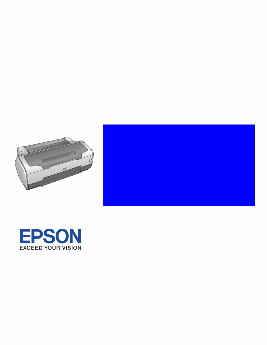
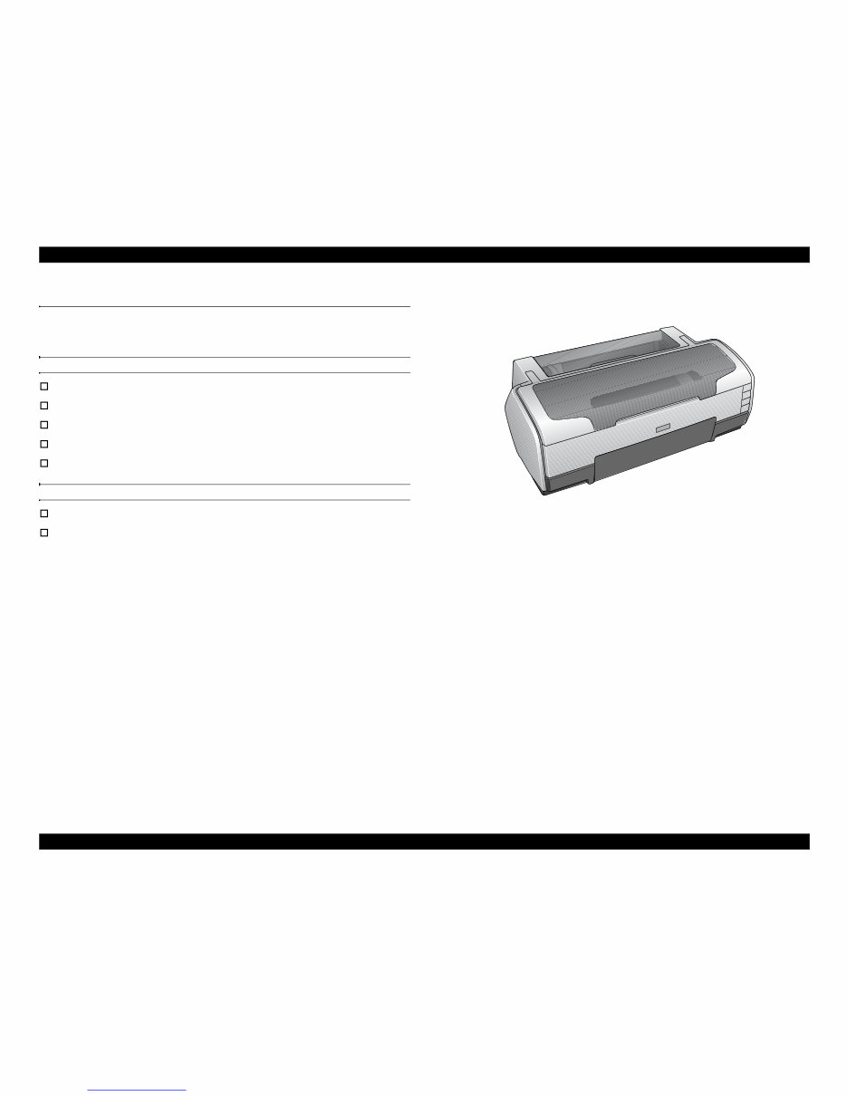
EPSON Stylus Photo 1390/1400/1410 Revision B PRODUCT DESCRIPTION Overview 9 1.1 Overview EPSON Stylus Photo 1390/1400/1410 is a color inkjet printer designed for a wide range of users, from home use to office use. The main features of this printer are: Features of Stylus Photo 1390/1400/1410 EPSON’s latest dye ink ensures high levels of lightfastness and gasfastness Six individually replaceable ink cartridges Offers high resolution of up to 5760 x 1440 dpi (dots per inch). Supports borderless print on up to A3+ sized paper High-quality and high-speed printing Features exclusive to Stylus Photo 1400/1410 Direct print on CD-R with the CD/DVD tray Direct print from PictBridge- and USB Direct Print-compatible digital cameras Figure 1-1. External View Downloaded from www.Manualslib.com manuals search engine
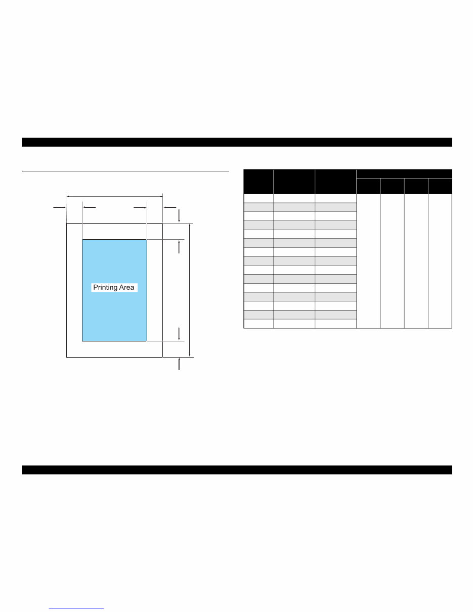
EPSON Stylus Photo 1390/1400/1410 Revision B PRODUCT DESCRIPTION Printing Area 10 1.2 Printing Area The printing area for this printer is shown below. Figure 1-2. Printing Area Note *1: Bottom margin can be reduced to 3 mm (minimum) by specifying the paper length via ESC (S command, however, print quality may not be acceptable in the area 3 mm to 43.3 mm (0.12 in. to 1.7 in.) from the bottom edge. When paper length is not specified, the bottom margin will be 3 mm or more. *2: EAI models only. *3: Except for EAI models. Note 1: Under the specific conditions, margins on all sides can be reduced to 0 mm. 2: Under the specific conditions, margins on both left and right sides can be reduced to 0 mm. PW LM RM TM BM PL Table 1-1. Printing Area Paper Size Width (PW) Length (PL) Margin Left (LM) Right (RM) Top (TM) Bottom (BM) *1 A3+ 329 mm (12.9 in.) 483 mm (19 in.) 3 mm (0.12 in.) or more 3 mm (0.12 in.) or more 3 mm (0.12 in.) or more 3 mm (0.12 in.) or more A3 297 mm (11.7 in.) 420 mm (16.5 in.) US B *2 279.4 mm (11 in.) 431.8 mm (17 in.) B4 257 mm (10.1 in.) 364 mm (14.3 in.) US Legal 216 mm (8.5 in.) 356 mm (14 in.) US Letter 216 mm (8.5 in.) 279 mm (10.9 in.) A4 210 mm (8.3 in.) 297 mm (11.7 in.) B5 *3 182 mm (7.2 in.) 257 mm (10.1 in.) A5 *3 148 mm (5.8 in.) 210 mm (8.3 in.) Half letter *2 139.7 mm (5.5 in.) 215.9 mm (8.5 in.) A6 105 mm (4.1 in.) 148 mm (5.8 in.) 8x10 *2 203.2 mm (8 in.) 254 mm (10 in.) 5x7 127 mm (5 in.) 262 mm (10.3 in.) 4x6 101.6 mm (4 in.) 152.4 mm (6 in.) 16:9 Wide 101.6 mm (4 in.) 180.6 mm (7.1 in.) Downloaded from www.Manualslib.com manuals search engine
You're Reading a Preview
What's Included?
Lifetime Access
Fast Download Speeds
Online & Offline Access
Access PDF Contents & Bookmarks
Full Search Facility
Print one or all pages of your manual
$28.99$37.99
EPSON Stylus Photo 1400/1410 Color Inkjet Printer Service Repair Manual
This is a comprehensive Service Repair Manual for the EPSON Stylus Photo 1400/1410 Color Inkjet Printer. The manual contains easy-to-understand text sections, high-quality diagrams, and detailed instructions for repairing your EPSON printer. It is a valuable resource for learning technical theory, installation, maintenance, troubleshooting, disassembly, assembly, and repair of EPSON products.
Models Covered:
EPSON Stylus Photo 1400 Color Inkjet Printer
EPSON Stylus Photo 1410 Color Inkjet Printer
This Manual Covers:
CHAPTER 1. PRODUCT DESCRIPTIONS
CHAPTER 2. OPERATING PRINCIPLES
CHAPTER 3. TROUBLESHOOTING
CHAPTER 4. DISASSEMBLY / ASSEMBLY
CHAPTER 5. ADJUSTMENT
CHAPTER 6. MAINTENANCE
APPENDIX
Model Specification: EPSON Stylus Photo 1400/1410 Color Inkjet Printer
Total Pages: 163
File Format: PDF
Requirements: Adobe Reader
Language: English
Compatible: All Versions of Windows & Mac, APP ISO, Iphone, Ipad, Android etc...
This manual is in PDF format. The Service Manual is fully indexed and bookmarked by topic, ensuring easy navigation. It is an original Adobe document, guaranteeing high-quality printing. The PDF can be quickly searched to find information in every chapter. You have the flexibility to print the entire manual or select specific pages. Additionally, you can zoom in on any diagram or picture for detailed viewing of every part.
Save time and money by performing your own repairs using this manual, which provides easy-to-follow, step-by-step instructions and detailed pictures for all repair areas.
All Service Repair Manuals are instant downloads, eliminating shipping costs and waiting time for a CD or paper manual. Upon payment completion through our secure processor, you will instantly receive this manual. We accept all major credit/debit cards and PayPal.
Reviews
Q&A
Recently Viewed
5,521,897Happy Clients
2,594,462eManuals
1,120,453Trusted Sellers
15Years in Business
Price:
Actual Price:
EPSON Stylus Photo 1400/1410 Color Inkjet Printer Service Repair Manual









 Lifetime Access




