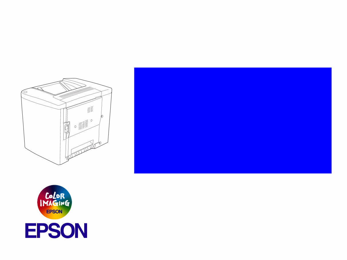
EPSON AcuLaser C1900 AcuLaser C900 A4 Color Page Printer ® SERVICE MANUAL SEPG02003
About This Manual This manual describes basic functions, theory of electrical and mechanical operations, maintenance and repair procedures of the printer. The instructions and procedures included herein are intended for the experienced repair technicians, and attention should be given to the precautions on the preceding page. Manual Configuration This manual consists of six chapters and Appendix. CHAPTER 1.PRODUCT DESCRIPTIONS Provides a general overview and specifications of the product. CHAPTER 2.OPERATING PRINCIPLES Describes the theory of electrical and mechanical operations of the product. CHAPTER 3.TROUBLESHOOTING Describes the step-by-step procedures for the troubleshooting. CHAPTER 4.DISASSEMBLY / ASSEMBLY Describes the step-by-step procedures for disassembling and assembling the product. CHAPTER 5.ADJUSTMENT Provides Epson-approved methods for adjustment. CHAPTER 6.MAINTENANCE Provides preventive maintenance procedures and the lists of Epson-approved lubricants and adhesives required for servicing the product. APPENDIX Provides the following additional information for reference: • Connector pin assignments • Electric circuit boards components layout • Electrical circuit boards schematics • Exploded diagram & Parts List Symbols Used in this Manual Various symbols are used throughout this manual either to provide additional information on a specific topic or to warn of possible danger present during a procedure or an action. Be aware of all symbols when they are used, and always read NOTE, CAUTION, or WARNING messages. Indicates an operating or maintenance procedure, practice or condition that is necessary to keep the product’s quality. Indicates an operating or maintenance procedure, practice, or condition that, if not strictly observed, could result in damage to, or destruction of, equipment. May indicate an operating or maintenance procedure, practice or condition that is necessary to accomplish a task efficiently. It may also provide additional information that is related to a specific subject, or comment on the results achieved through a previous action. Indicates an operating or maintenance procedure, practice or condition that, if not strictly observed, could result in injury or loss of life. A D J U S T M E N T R E Q U I R E D C A U T I O N C H E C K P O I N T W A R N I N G
Safety Precautions for Inspection and Service When performing inspection and service procedures, observe the following precautions to prevent accidents and ensure utmost safety. * Depending on the model, some of the precautions given in the following do not apply. Different markings are used to denote specific meanings as detailed below. The following graphic symbols are used to give instructions that need to be observed. WARNING W A R N I N G Indicates a potentially hazardous situation which, if not avoided, could result in death or serious injury. C A U T I O N Indicates a potentially hazardous situation which, if not avoided, may result in minor or moderate injury. It may also be used to alert against unsafe practices. Used to call the service technician's attention to what is graphically represented inside the marking (including a warning). Used to prohibit the service technician's from doing what is graphically represented inside the marking. Used to instruct the service technician's to do what is graphically represented inside the marking. 1.Always observe precautions. Parts requiring special attention in this product will include a label containing the mark shown on the left plus precautionary notes. Be sure to observe the precautions. Be sure to observe the “Safety Information” given in the Operator's Manual. 2.Before starting the procedures, be sure to unplug the power cord. This product contains a high-voltage unit and a circuit with a large current capacity that may cause an electric shock or burn. The product also contains parts that can jerk suddenly and cause injury. If this product uses a laser, laser beam leakage may cause eye damage or blindness. 3.Use the specified parts. For replacement parts, always use the genuine parts specified in the manufacturer's parts manual. Installing a wrong or unauthorized part could cause dielectric breakdown, overload, or undermine safety devices resulting in possible electric shock or fire. Replace a blown electrical fuse or thermal fuse with its corresponding genuine part specified in the manufacturer's parts manual. Installing a fuse of a different make or rating could lead to a possible fire. If a thermal fuse blows frequently, the temperature control system may have a problem and action must be taken to eliminate the cause of the problem. W A R N I N G
4.Handle the power cord with care and never use a multiple outlet. Do not break, crush or otherwise damage the power cord. Placing a heavy object on the power cord, or pulling or bending it may damage it, resulting in a possible fire or electric shock. Do not use a multiple outlet to which any other appliance or machine is connected. Be sure the power outlet meets or exceeds the specified capacity. 5.Be careful with the high-voltage parts. A part marked with the symbol shown on the left carries a high voltage. Touching it could result in an electric shock or burn. Be sure to unplug the power cord before servicing this part or the parts near it. 6.Do not work with wet hands. Do not unplug or plug in the power cord, or perform any kind of service or inspection with wet hands. Doing so could result in an electric shock. 7.Do not touch a high-temperature part. A part marked with the symbol shown on the left and other parts such as the exposure lamp and fusing roller can be very hot while the machine is energized. Touching them may result in a burn. Wait until these parts have cooled down before replacing them or any surrounding parts. 8.Maintain a grounded connection at all times. (This item may not apply in the USA.) Be sure to connect the ground wire to the ground terminal even when performing an inspection or repair. Without proper grounding, electrical leakage could result in an electric shock or fire. Never connect the ground wire to a gas pipe, water pipe, telephone ground wire, or a lightning conductor. 9.Do not remodel the product. Modifying this product in a manner not authorized by the manufacturer may result in a fire or electric shock. If this product uses a laser, laser beam leakage may cause eye damage or blindness. 10.Restore all parts and harnesses to their original positions. To promote safety and prevent product damage, make sure the harnesses are returned to their original positions and properly secured in their clamps and saddles in order to avoid hot parts, high-voltage parts, sharp edges, or being crushed. To promote safety, make sure that all tubing and other insulating materials are returned to their original positions. Make sure that floating components mounted on the circuit boards are at their correct distance and position off the boards.
CAUTION 1.Precautions for Service Jobs A toothed washer and spring washer, if used originally, must be reinstalled. Omitting them may result in contact failure which could cause an electric shock or fire. When reassembling parts, make sure that the correct screws (size, type) are used in the correct places. Using the wrong screw could lead to stripped threads, poorly secured parts, poor insulating or grounding, and result in a malfunction, electric shock or injury. Take great care to avoid personal injury from possible burrs and sharp edges on the parts, frames and chassis of the product. When moving the product or removing an option, use care not to injure your back or allow your hands to be caught in mechanisms. 2.Precautions for Servicing with Covers and Parts Removed Wherever feasible, keep all parts and covers mounted when energizing the product. If energizing the product with a cover removed is absolutely unavoidable, do not touch any exposed live parts and use care not to allow your clothing to be caught in the moving parts. Never leave a product in this condition unattended. Never place disassembled parts or a container of liquid on the product. Parts falling into, or the liquid spilling inside, the mechanism could result in an electric shock or fire. Never use a flammable spray near the product. This could result in a fire. Make sure the power cord is unplugged before removing or installing circuit boards or plugging in or unplugging connectors. Always use the interlock switch actuating jig to actuate an interlock switch when a cover is opened or removed. The use of folded paper or some other object may damage the interlock switch mechanism, possibly resulting in an electric shock, injury or blindness. C A U T I O N 3.Precautions for the Working Environment The product must be placed on a flat, level surface that is stable and secure. Never place this product or its parts on an unsteady or tilting workbench when servicing. Provide good ventilation at regular intervals if a service job must be done in a confined space for a long period of time. Avoid dusty locations and places exposed to oil or steam. Avoid working positions that may block the ventilation ports of the product. 4.Precautions for Handling Batteries (Lithium, Nickel-Cadmium, etc.) Replace a rundown battery with the same type as specified in the manufacturer's parts manual. Before installing a new battery, make sure of the correct polarity of the installation or the battery could burst. Dispose of used batteries according to the local regulations. Never dispose of them at the user's premises or attempt to try to discharge one.
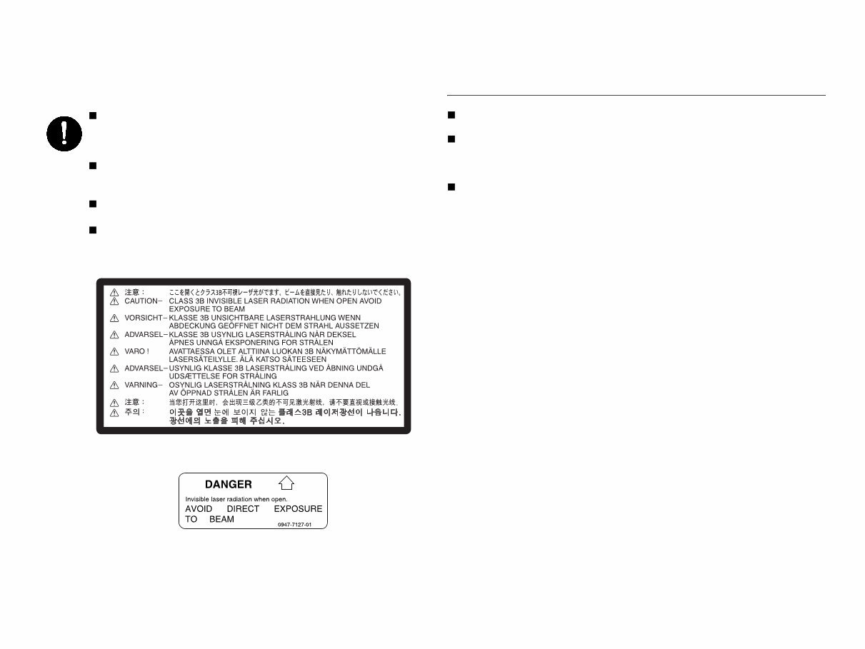
Other Precautions When handling circuit boards, observe the “HANDLING of PWBs”. The PC Drum is a very delicate component. Observe the precautions given in “HANDLING OF THE PC DRUM” because mishandling may result in serious image problems. Note that replacement of a circuit board may call for readjustments or resetting of particular items, or software installation. 5.Precautions for the Laser Beam (Only for Products Employing a Laser) Removing the cover marked with the following caution label could lead to possible exposure to the laser beam, resulting in eye damage or blindness. Be sure to unplug the power cord before removing this cover. If removing this cover while the power is ON is unavoidable, be sure to wear protective laser goggles that meet specifications. Make sure that no one enters the room when the machine is in this condition. When handling the laser unit, observe the “Precautions for Handling Laser Equipment.”
Precautions for Service When performing inspection and service procedures, observe the following precautions to prevent mishandling of the machine and its parts. * Depending on the model, some of the precautions given in the following do not apply. PRECAUTIONS BEFORE SERVICE When the user is using a word processor or personal computer from a wall outlet of the same line, take necessary steps to prevent the circuit breaker from opening due to overloads. Never disturb the LAN by breaking or making a network connection, altering termination, installing or removing networking hardware or software, or shutting down networked devices without the knowledge and express permission of the network administrator or the shop supervisor. HOW TO USE THIS BOOK DIS/REASSEMBLY, ADJUSTMENT To reassemble the product, reverse the order of disassembly unless otherwise specified. TROUBLESHOOTING If a component on a PWB or any other functional unit including a motor is defective, the text only instructs you to replace the whole PWB or functional unit and does not give troubleshooting procedures applicable within the defective unit. All troubleshooting procedures contained herein assume that there are no breaks in the harnesses and cords and all connectors are plugged into the right positions. The procedures preclude possible malfunctions due to noise and other external causes. PRECAUTIONS FOR SERVICE Check the area surrounding the service site for any signs of damage, wear or need of repair. Keep all disassembled parts in good order and keep tools under control so that none will be lost or damaged. After completing a service job, perform a safety check. Make sure that all parts, wiring and screws are returned to their original positions. Do not pull out the toner hopper while the toner bottle is turning. This could result in a damaged motor or locking mechanism. If the product is to be run with the front door open, make sure that the toner hopper is in the locked position. Do not use an air gun or vacuum cleaner for cleaning the ATDC Sensor and other sensors, as they can cause electrostatic destruction. Use a blower brush and cloth. If a unit containing these sensors is to be cleaned, first remove the sensors from the unit.
PRECAUTIONS FOR DISASSEMBLY/REASSEMBLY Be sure to unplug the copier from the outlet before attempting to service the copier. The basic rule is not to operate the copier anytime during disassembly. If it is absolutely necessary to run the copier with its covers removed, use care not to allow your clothing to be caught in revolving parts such as the timing belt and gears. Before attempting to replace parts and unplug connectors, make sure that the power cord of the copier has been unplugged from the wall outlet. Be sure to use the Interlock Switch Actuating Jig whenever it is necessary to actuate the Interlock Switch with the covers left open or removed. While the product is energized, do not unplug or plug connectors into the circuit boards or harnesses. Never use flammable sprays near the copier. A used battery should be disposed of according to the local regulations and never be discarded casually or left unattended at the user's premises. When reassembling parts, make sure that the correct screws (size, type) and toothed washer are used in the correct places. If it becomes necessary to replace the thermal fuse or any other fuse mounted on a board, be sure to use one of the rating marked on the blown fuse. Always note the rating marked on the fuse, as the rating and mounting site or number used are subject to change without notice. PRECAUTIONS FOR CIRCUIT INSPECTION Never create a closed circuit across connector pins except those specified in the text and on the printed circuit. When creating a closed circuit and measuring a voltage across connector pins specified in the text, be sure to use the GND wire. HANDLING OF PWBS During Transportation/Storage: During transportation or when in storage, new P.W. Boards must not be indiscriminately removed from their protective conductive bags. Do not store or place P.W. Boards in a location exposed to direct sunlight and high temperature. When it becomes absolutely necessary to remove a Board from its conductive bag or case, always place it on its conductive mat in an area as free as possible from static electricity. Do not touch the pins of the ICs with your bare hands. Protect the PWBs from any external force so that they are not bent or damaged. During Inspection/Replacement: Avoid checking the IC directly with a multimeter; use connectors on the Board. Never create a closed circuit across IC pins with a metal tool. Before unplugging connectors from the P.W. Boards, make sure that the power cord has been unplugged from the outlet.
When removing a Board from its conductive bag or conductive case, do not touch the pins of the ICs or the printed pattern. Place it in position by holding only the edges of the Board. When touching the PWB, wear a wrist strap and connect its cord to a securely grounded place whenever possible. If you cannot wear a wrist strap, touch a metal part to discharge static electricity before touching the PWB. Note that replacement of a PWB may call for readjustments or resetting of particular items. HANDLING OF OTHER PARTS The magnet roller generates a strong magnetic field. Do not bring it near a watch, floppy disk, magnetic card, or CRT tube. HANDLING OF THE PC DRUM * Only for Products Not Employing an Imaging Cartridge. During Transportation/Storage: Use the specified carton whenever moving or storing the PC Drum. The storage temperature is in the range between -20°C and +40°C. In summer, avoid leaving the PC Drum in a car for a long time. Handling: Ensure that the correct PC Drum is used. Whenever the PC Drum has been removed from the copier, store it in its carton or protect it with a Drum Cloth. The PC Drum exhibits greatest light fatigue after being exposed to strong light over an extended period of time. Never, therefore, expose it to direct sunlight. Use care not to contaminate the surface of the PC Drum with oil- base solvent, fingerprints, and other foreign matter. Do not scratch the surface of the PC Drum. Do not apply chemicals to the surface of the PC Drum. Do not attempt to wipe clean the surface of the PC Drum.
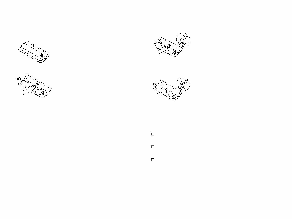
If, however, the surface is contaminated with fingerprints, clean it using the following procedure. NOTE: Even when the PC Drum is only locally dirtied, wipe the entire surface. Do not expose the PC Drum to direct sunlight. Clean it as quickly as possible even under interior illumination. If dirt remains after cleaning, repeat the entire procedure from the beginning one more time. 1. Place the PC Drum into one half of its carton. 2. Gently wipe the residual toner off the surface of the PC Drum with a dry, Dust- Free Cotton Pad. A.Turn the PC Drum so that the area of its surface on which the line of toner left by the Cleaning Blade is present is facing straight up. Wipe the surface in one continuous movement from the rear edge of the PC Drum to the front edge and off the surface of the PC Drum. B. Turn the PC Drum slightly and wipe the newly exposed surface area with a CLEAN face of the Dust-Free Cotton Pad. Repeat this procedure until the entire surface of the PC Drum has been thoroughly cleaned. *At this time, always use a CLEAN face of the dry Dust-Free Cotton Pad until no toner is evident on the face of the Pad after wiping. 3. Soak a small amount of either ethyl alcohol or isopropyl alcohol into a clean, unused Dust-Free Cotton Pad which has been folded over into quarters. Now, wipe the surface of the PC Drum in one continuous movement from its rear edge to its front edge and off its surface one to two times. *Never move the Pad back and forth. 4. Using the SAME face of the Pad, repeat the procedure explained in the latter half of step 3 until the entire surface of the PC Drum has been wiped. Always OVERLAP the areas when wiping. Two complete turns of the PC Drum would be appropriate for cleaning.
You're Reading a Preview
What's Included?
Lifetime Access
Fast Download Speeds
Online & Offline Access
Access PDF Contents & Bookmarks
Full Search Facility
Print one or all pages of your manual
$30.99
Epson AcuLaser C1900 / AcuLaser C900 A4 Color Page Printer Service Repair Manual
This is a comprehensive Service Repair Manual for the Epson AcuLaser C1900 and AcuLaser C900 A4 Color Page Printers. The manual includes easy-to-understand text sections, high-quality diagrams, and step-by-step instructions for repairing your EPSON machine. It is designed to facilitate learning of technical theory, installation, maintenance, troubleshooting, disassembly, assembly, and repair of EPSON products.
Models Covered:
Epson AcuLaser C1900 A4 Color Page Printer
Epson AcuLaser C900 A4 Color Page Printer
Manual Contents:
CHAPTER 1: PRODUCT DESCRIPTIONS
CHAPTER 2: OPERATING PRINCIPLES
CHAPTER 3: TROUBLESHOOTING
CHAPTER 4: DISASSEMBLY / ASSEMBLY
CHAPTER 5: ADJUSTMENT
CHAPTER 6: MAINTENANCE
APPENDIX
Model Specification: Epson AcuLaser C1900 / AcuLaser C900 A4 Color Page Printer
Total Pages: 270
Language: English
File Format: PDF
Requirements: Adobe Reader
Compatibility: All Versions of Windows & Mac, APP ISO, iPhone, iPad, Android, etc.
This manual is in PDF format and is fully indexed and bookmarked by topic. It is an original Adobe document, ensuring perfect quality and printing. The PDF can be quickly searched to find information in every chapter. Users have the option to print the entire manual or select specific pages. Additionally, it allows zooming in on diagrams or pictures for detailed viewing of every part.
By using this manual, individuals can save time and money by performing their own repairs. The manual provides easy-to-follow, step-by-step instructions and pictures for all areas of repair.
Instant Access: All Service Repair Manuals are instantly accessible, eliminating shipping costs and waiting time for a CD or paper manual to arrive. Upon payment completion via the secure payment processor, the manual can be received instantly. Accepted payment methods include all major credit/debit cards and PayPal.
Reviews
Q&A
Recently Viewed
5,521,897Happy Clients
2,594,462eManuals
1,120,453Trusted Sellers
15Years in Business
Price:
Actual Price:
Epson AcuLaser C1900 / AcuLaser C900 A4 Color Page Printer Service Repair Manual










 Lifetime Access




