Scope This manual has been issued by Canon Inc., to provide the service technicians of this product with the information necessary for qualified persons to learn technical theory, installation, maintenance, and repair of products. The manual covers information applicable in all regions where the product is sold. For this reason, it may contain information that is not applicable to your region. Revision This manual could include technical inaccuracies or typographical errors due to improvements or changes made to the product. When changes are made to the contents of the manual, Canon will release technical information when necessary. When substantial changes are made to the contents of the manual, Canon will issue a revised edition. The following do not apply if they do not conform to the laws and regulations of the region where the manual or product is used: Trademarks Product and brand names appearing in this manual are registered trademarks or trademarks of the respective holders. Copyright All rights reserved. No parts of this manual may be reproduced in any form or by any means or translated into another language without the written permission of Canon Inc., except in the case of internal business use. Copyright 2003 by Canon Inc. CANON INC. Inkjet Products Quality Assurance Div. 16-1, Shimonoge 3-chome, Takatsu-ku, Kawasaki, Kanagawa 213-8512, Japan
I. MANUAL OUTLINE This manual consists of the following three parts to provide information necessary to service the i900D/i905D: Part 1: Maintenance Information on maintenance and troubleshooting of the i900D/i905D Part 2: Technical Reference New technology and technical information such as FAQ’s (Frequently Asked Questions) of the i900D/i905D Part 3: Appendix Block diagrams and pin layouts of the i900D/i905D Reference: This manual does not provide sufficient information of disassembly and reassembly procedures. Refer to the graphics in the separate Parts Catalog.
II. TABLE OF CONTENTS Page Part 1: MAINTENANCE 1-1 1. MAINTENANCE 1.1 Adjustment, Periodic Maintenance, Periodic Replacement Parts, and Replacement Consumables by Service Engineer 1-2 1.2 Customer Maintenance 1-3 1.3 Product Life 1.4 Special Tools 1.5 Serial Number Location 1-4 2. LIST OF ERROR DISPLAY / INDICATION 2.1 Operator Call Errors (by LED Blinking in Orange) 1-5 2.2 Service Call Errors 1-6 2.3 Warnings 1-7 2.4 Troubleshooting by Symptom 1-8 3. REPAIR 3.1 Notes on Service Part Replacement (and Disassembling / Reassembling) 1-10 3.2 Special Notes on Repair Servicing 1-12 3.3 Adjustment / Settings (1) Paper feed motor adjustment (2) Gear phase adjustment (3) Grease application (4) Waste ink counter setting (5) User mode (6) Service mode (7) Flash ROM upgrade 1-20 3.4 Verification Items (1) Service test print (2) EEPROM information print 1-22 4. PRINTER TRANSPORTATION METHOD Part 2: TECHNICAL REFERENCE 2-1 1. NEW TECHNOLOGIES 2-4 2. CLEANING MODE AND AMOUNT OF INK PURGED 2-5 3. PRINT MODE 2-7 4. PHOTO DIRECT PRINT FUNCTION 4.1 Host PC Memory Card Access Function with the Memory Card Startup Utility 2-8 4.2 Memory Card Direct Printing Function 2-10 4.3 File Search 2-11 4.4 File Sort 4.5 Date Print 2-12 4.6 Bubble Jet Direct Function 2-14 4.7 PictBridge Function 2-15 4.8 Exclusive Processes 2-16 4.9 LCD Viewer 2-17 4.10 Card Slot-related Operations and Display 2-18 4.11 DPOF Settings in the Memory Card Direct Printing Function 2-19 4.12 Print Layout (Details) 2-21 4.13 Date Print Specifications 2-22 4-14 Photo Number Printing Specifications 2-23 5. FAQ (Specific Problems and Solutions) Part 3: APPENDIX 3-1 1. BLOCK DIAGRAM 3-2 2. CONNECTOR LOCATION AND PIN LAYOUT 2.1 Logic Board Ass’y 3-6 2.2 USB I/F Board (DCC Cover Unit) for Camera Direct Printing 3-7 2.3 Operation Panel Board 3-8 2.4 Memory Card Board 3-12 2.5 Carriage Board (Print Head Connector)
Part 1 MAINTENANCE
1. MAINTENANCE 1.1 Adjustment, Periodic Maintenance, Periodic Replacement Parts, and Replacement Consumables by Service Engineer (1) Adjustment Adjustment Timing Purpose Tool Approx. time EEPROM initialization (EEPROM settings) At logic board ass’y replacement To initialize settings other than the following: - USB serial number - Destination setting (The language to be displayed on the LCD viewer is set to the default setting for each destination.) - Waste ink counter - Media sensor correction value - CD-R correction value None. 1 min. Destination settings (EEPROM settings) At logic board ass’y replacement To set the destination. None. 1 min. LCD viewer language settings At logic board ass’y replacement To set the language to be displayed on the LCD viewer. None. 1 min. Waste ink counter resetting - At bottom case unit replacement - At ink absorber (QC1-2232 / 2233 / 2234 / 2235 / 2236) replacement To reset the waste ink counter. None. 1 min. Media sensor correction*1 (EEPROM settings) - At logic board ass’y replacement - At sheet feeder unit replacement To correct the media sensor. Calibration media kit (QY9-0064) 2 min. CD-R sensor / automatic print head alignment sensor correction (EEPROM settings) - At logic board ass’y replacement - At carriage unit replacement To correct the CD-R and automatic print head alignment sensor. None. (Correction performed through service test print) 1 min. Print head alignment - At print head replacement - At logic board ass’y replacement To ensure accurate dot placement. - None. (printer buttons) - Computer (settings via the printer driver) 2 min. Paper feed motor position adjustment*2 At paper feed motor unit replacement To adjust the belt tension. (Position the paper feed motor so that the belt is stretched tight.) None. 2 min. Grease application - At carriage unit replacement - At paper guide flapper ass’y (QL2-0341) replacement - At lift cam base’s (QL2-0340) gear replacement - At lift cam shaft unit (QM2-0593) replacement - To maintain sliding properties of the carriage, carriage shaft, paper guide flapper, and lift cam shaft. - To protect the lift cam base gear. - FLOIL KG-107A (QY9-0057) - MOLYKOTE PG641 (CK-0562) 2 min. Note: DO NOT loosen the red screws on both sides of the main chassis, securing the carriage shaft positioning. *1: Media sensor correction This operation adjusts the correction value of the media sensor, installed in the sheet feeder unit, to the EEPROM of the logic board ass’y. The adjustment is required when the sheet feeder unit or the logic board ass’y is replaced, and values are automatically determined via use of calibration media kit (QY9-0064: 10 sheet of reference plain paper and one sheet of reference white PET paper). *2: Red screws of paper feed motor The red screws securing the paper feed motor may be loosened only at replacement of the paper feed motor unit. 1 - 1
(2) Periodic maintenance No periodic maintenance is necessary. (3) Periodic replacement parts There are no parts in this printer that require periodic replacement by a service engineer. (4) Replacement consumables There are no consumables that require replacement by a service engineer. 1.2 Customer Maintenance Adjustment Timing Purpose Tool Approx. time Print head alignment At print head replacement. To ensure accurate dot placement. - Printer buttons - Computer (settings via the printer driver) 3 min. Print head cleaning When print quality is not satisfying. To improve nozzle conditions. - Printer buttons - Computer (settings via the printer driver) 30 sec. to 1 min. Print head deep cleaning When print quality is not satisfying, and not improved by print head cleaning. To improve nozzle conditions. - Printer buttons - Computer (settings via the printer driver) 1 to 1.5 min. Ink tank replacement When an ink tank becomes empty. (No ink error) ----- ----- 2 min. Paper feed roller cleaning When paper does not feed properly. To clean the paper feed rollers. Printer buttons 2 min. CD-R print position adjustment At CD-R printing, when necessary To correct CD-R print position Computer (application software) 5 min. LCD viewer contrast adjustment When adjusting the contrast To adjust the contrast Printer buttons 1 min. 1 - 2
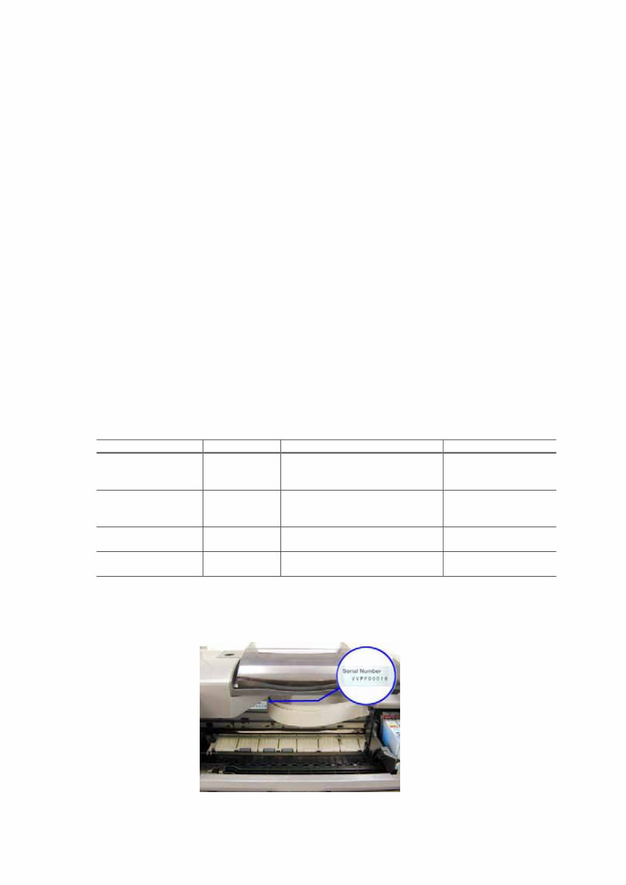
1.3 Product Life (1) Printer The value (i) or (ii), whichever comes first. (i) 5,000 pages of printing - Black: 1,500 pages (A4, 1,500 character pattern) - Color: 3,500 pages (A4, 7.5% duty per color pattern: 1,300 pages A4, 30% duty per color pattern: 400 pages Postcard, 30% duty per color pattern: 800 pages L-size, 30% duty per color pattern: 1,000 pages) (ii) 5 years of use (2) Print head 5,000 pages (in the above print modes) (3) Ink tank BCI-6BK: 540 pages (JEIDA standard pattern J1, plain paper, standard mode) 520 pages (1,500 character pattern in black printing, plain paper, standard mode) 540 pages (ISO JIS-SCID No. 5 pattern, plain paper, standard mode) BCI-6C: 780 pages (ISO JIS-SCID No. 5 pattern, plain paper, standard mode) BCI-6M: 580 pages (ISO JIS-SCID No. 5 pattern, plain paper, standard mode) BCI-6Y: 360 pages (ISO JIS-SCID No. 5 pattern, plain paper, standard mode) BCI-6PC: 410 pages (ISO JIS-SCID No. 5 pattern, plain paper, standard mode) BCI-6PM: 260 pages (ISO JIS-SCID No. 5 pattern, plain paper, standard mode) 1.4 Special Tools Name Tool No. Purpose Remarks MOLYKOTE PG641 CK-0562-000 To be applied to the lift cam base’s upper gear and the sliding portion of the lift cam shaft In common with conventional models FLOIL KG-107A QY9-0057-000 To be applied to the sliding portions of the carriage, carriage shaft, and the paper guide flapper In common with conventional models GREASE EU1 QY9-0037-000 To be applied to the carriage shaft bearing In common with conventional models Calibration media kit QY9-0064-000 To correct the media sensor In common with conventional models 1.5 Serial Number Location Visible when the access cover is open. 1 - 3
2. LIST OF ERROR DISPLAY / INDICATION Errors are indicated by the LED, and warnings are displayed on the monitor of the computer connected to the printer. (1) Errors are indicated by the number of times the LED blinks. (2) Errors are indicated in the LCD viewer on the operation panel. (3) Warnings are displayed in the Status Monitor of the printer driver. 2.1 Operator Call Errors (by LED Blinking in Orange) LED blinking in orange Error Solution Remarks No paper. (ASF) [1000] Set the paper in the ASF, and press the Resume button. No CD-R tray. [1001] *1 Set the CD-R tray, and press the Resume button. 2 times No paper in the photo paper tray. [1004] Set the paper in the photo paper tray, and press the Resume button. 3 times Paper jam. [1300] Remove the jammed paper, and press the Resume button. 4 times No ink. [1601/1602/1611/1612/1613/1634/ 1635] Replace the empty ink tank(s), or press the Resume button. Pressing the Resume button will exit the error without ink tank replacement, however, ink may run out during printing. 5 times The print head is not installed [1401], or it is not properly installed (EEPROM data of the print head is faulty) [1403/1405]. Install the print head properly, and close the front cover. Or, with the print head installed, turn the printer off and on. No CD-R tray feeder (during CD-R printing). [1850/1855] Set the CD-R tray and tray feeder properly, and press the Resume button. 6 times *1 Presence of the CD-R tray feeder (during paper printing). [1851/1856] Remove the CD-R tray feeder, and press the Resume button. 7 times *1 No CD-R or DVD-R. [1002] After setting a CD-R or DVD-R in the tray, set the tray in the tray feeder, and press the Resume button. 8 times Warning: The waste ink absorber becomes almost full (approx. 95% of the maximum capacity). [1700] Pressing the Resume button will exit the error, and enable printing. In repair servicing, replace the bottom case unit (QM2-0663), or 5-item set of the ink absorbers (QC1-2232/2233/2234/2235/2236). The service call error, indicating the waste ink absorber is full, is likely to occur soon. 9 times The connected digital camera or digital video camera does not support Camera Direct Printing. [2001] After removing the cable between the camera and the printer, press the Resume button, and re-connect the cable. When connected to a Direct Print supported camera, the green LED blinks 2 times. 11 times Automatic print head alignment failure. [2500] Press the Resume button, and after confirming the following, perform print head alignment again: - Set an appropriate type and size of paper (plain paper, A4 or letter). - Check that the nozzle check pattern is properly printed (all ink ejected, no faint printing) - Check that the paper output slot is not exposed to light. * 1 : Only for the model supporting CD-R printing (i905D only) 1 - 4
This is the complete factory Service Repair Manual for the Canon PIXUS 900PD / i900D / i905D Printer. The manual contains easy-to-read text sections with high-quality diagrams and instructions, providing step-by-step guidance for repairing your CANON machine.
Model Specification: Canon PIXUS 900PD / i900D / i905D Printer
File Format: .PDF
Requirements: Adobe Reader
Language: English
Compatibility: All Versions of Windows & Mac, APP ISO, Iphone, Ipad, Android etc...
This manual is in .PDF format and is fully indexed and bookmarked by topic. It is an original Adobe document, ensuring perfect quality and printing. The manual can be quickly searched to find information in every chapter. You have the option to print the entire manual or select specific pages. Additionally, you can zoom in on any diagram or picture to clearly see every part.
By using this manual, you can save time and money by performing your own repairs. The manual provides easy-to-follow, step-by-step instructions and pictures for all areas of repair.
All Service Repair Manuals are instant downloads, eliminating shipping costs and the need to wait for a CD or paper manual to arrive. Upon completion of payment via our secure payment processor, you will receive this manual instantly. We accept all major credit/debit cards and PayPal.