I. MANUAL OUTLINE This manual consists of the following three parts to provide information necessary to service the PIXMA iX5000 / iX4000: Part 1: Maintenance Information on maintenance and troubleshooting of the PIXMA iX5000 / iX4000 Part 2: Technical Reference New technology and technical information such as FAQ's (Frequently Asked Questions) of the PIXMA iX5000 / iX4000 Part 3: Appendix Block diagrams and pin layouts of the PIXMA iX5000 / iX4000 Reference: This manual does not provide sufficient information for disassembly and reassembly procedures. Refer to the graphics in the separate Parts Catalog.
II. TABLE OF CONTENTS Part 1: MAINTENANCE 1. MAINTENANCE 1-1. Adjustment, Periodic Maintenance, Periodic Replacement Parts, and Replacement Consumables by Service Engineer 1-2. Customer Maintenance 1-3. Product Life 1-4. Special Tools 1-5. Serial Number Location 2. LIST OF ERROR DISPLAY / INDICATION 2-1. Operator Call Errors 2-2. Service Call Errors 2-3. Warnings 2-4. Troubleshooting by Symptom 3. REPAIR 3-1. Notes on Service Part Replacement (and Disassembling / Reassembling) 3-2. Special Notes on Repair Servicing 3-3. Adjustment / Settings (1) Paper feed motor adjustment (2) Grease application (3) Waste ink counter setting (4) User mode (5) Service mode Service test print, EEPROM initialization, Waste ink counter reset Destination settings 3-4. Verification Items (1) Service test print (2) EEPROM information print 4. PRINTER TRANSPORTATION Part 2: TECHNICAL REFERENCE 1. NEW TECHNOLOGIES 2. CLEANING MODE AND AMOUNT OF INK PURGED 3. PRINT MODE 3-1. Normal Color Printing 3-2. Normal Grayscale Printing 3-3. Borderless Printing 3-4. Camera Direct Printing 4. FAQ (Problems Specific to the iP4000 and Corrective Actions) Part 3: APPENDIX 1. BLOCK DIAGRAM 2. CONNECTOR LOCATION AND PIN LAYOUT 2-1. Logic Board Ass'y 2-2. Carriage Board (Print Head Connector) 3. PIXMA iX5000 / iX4000 Specifications
Part 1 MAINTENANCE
1. MAINTENANCE 1-1. Adjustment, Periodic Maintenance, Periodic Replacement Parts, and Replacement Consumables by Service Engineer (1) Adjustment Note: DO NOT loosen the red screws at both ends of the carriage shaft, securing the print head position, as they are not re-adjustable. The red screws securing the paper feed motor may be loosened only at replacement of the paper feed motor unit. (2) Periodic maintenance No periodic maintenance is necessary. (3) Periodic replacement parts There are no parts in this printer that require periodic replacement by a service engineer. (4) Replacement consumables There are no consumables that require replacement by a service engineer. 1-2. Customer Maintenance Adjustment Timing Purpose Tool Approx. time Destination settings (EEPROM settings) At logic board replacement To set the destination. None. Perform in the service mode. 1 min. Waste ink counter resetting (EEPROM settings) - At logic board replacement - At waste ink absorber replacement To reset the waste ink counter. None. Perform in the service mode. 1 min. Paper feed motor position adjustment At paper feed motor replacement To adjust the belt tension. (Position the paper feed motor so that the belt is stretched tight.) None. 5 min. Grease application - At carriage unit replacement - At PS gear replacement - To maintain sliding properties of the carriage shaft. - To protect the printer's sliding portions (gears). FLOIL KG-107A 1 min. Ink system function check - At logic board replacement - At platen unit replacement - At carriage unit replacement To maintain detection functionality for presence of the ink tanks and each ink tank position. None. Perform in the service mode. 1 min. Adjustment Timing Purpose Tool Approx. time Print head alignment At print head replacement. To ensure accurate dot placement. - Printer buttons - Computer (automatic settings via the printer driver) 3 min. Print head cleaning When print quality is not satisfying. To improve nozzle conditions. - Printer buttons - Computer (settings via the printer driver) 1 min. Print head deep cleaning When print quality is not satisfying, and not improved by print head cleaning. To improve nozzle conditions. Computer (settings via the printer driver) 2 min. Ink tank replacement When an ink tank becomes empty. ("No ink error" via the computer, or ink tank LED flashing fast in red) ----- ----- 2 min. Paper feed roller cleaning When necessary To clean the paper feed rollers. Printer buttons 2 min. Bottom plate cleaning When the back side of the paper is smeared To clean the platen ribs. - Plain paper - Computer (settings via the printer driver)1 min. 1-1
1-3. Product Life (1) Printer Specified print volume (I) or the years of use (II), whichever comes first. (I) Print volume: 24,000 pages (II) Years of use: 5 years of use (2) Print head Print volume: 24,000 pages Black 1,500 character pattern 13,600 pages Color A4, 7.5% duty per color pattern 4,400 pages A4, photo, borderless printing 3,600 pages 4 x 6, photo, borderless printing 600 pages Postcard, photo, borderless printing 1,800 pages Black 1,500 character pattern 13,600 pages Color A4, 7.5% duty per color pattern 4,400 pages A4, photo, borderless printing 3,600 pages 4 x 6, photo, borderless printing 600 pages Postcard, photo, borderless printing 1,800 pages (3) Ink tank (target value) Pattern Ink tank used Print yield Black text PGI-5BK Approx. 800 pages Color chart PGI-5BK Approx. 1,400 pages CLI-8C Approx. 710 pages CLI-8M Approx. 470 pages CLI-8Y Approx. 460 pages Photo chart PGI-5BK Approx. 3,800 pages CLI-8C Approx. 380 pages CLI-8M Approx. 250 pages CLI-8Y Approx. 250 pages Black text: When printing the Canon standard pattern (1,500 characters per page) on A4 size plain paper, with the default settings in the Windows XP driver, using Word 2003. Color chart: When printing the ISO/JIS-SCID N5 pattern on A4 size plain paper in bordered printing, with the default settings in the Windows XP driver, using Photoshop 7.0. Photo chart: When printing the Canon standard pattern on 4" x 6" Photo Paper Plus Glossy in borderless printing, with the default settings in the Windows XP driver, using Windows XP Photo Printing Wizard. The print yield in the table above is an average value measured in continuous printing, using the ink tank immediately after it is unsealed, until the ink is out. Ink yield may vary depending on texts and photos printed, application software, print mode, and type of paper used. When the machine is turned on and while printing, each ink may be used for protecting the print head and maintaining print quality. 1-2
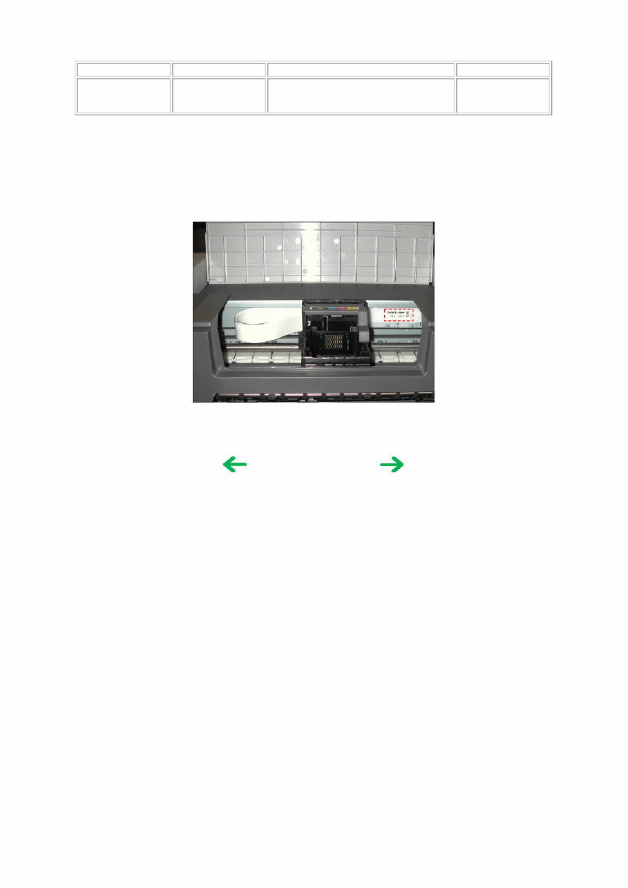
1-4. Special Tools 1-5. Serial Number Location On the carriage flexible cable holder (visible on the right of the carriage after the printer is turned on, the access cover is opened, and the carriage moves to the center). Name Tool No. Application Remarks FLOIL KG-107A QY9-0057-000 To be applied to the sliding portions of the carriage shaft, and printer's sliding portions (gears). In common with the S520. To the table of contents To the top <Part 1: 1. MAINTENANCE> 1-3
2. LIST OF ERROR DISPLAY / INDICATION Errors are indicated by the LED, and warnings are displayed on the monitor of the computer connected to the printer. 2-1. Operator Call Errors (by Alarm LED Blinking in Orange) Alarm LED blinking in orange Error [Error code] Solution Remarks 2 times No paper. (ASF) [1000] Set the paper in the ASF, and press the Resume/Cancel button. 3 times Paper jam. [1300] Remove the jammed paper, and press the Resume/Cancel button. Error in paper feeding from the ASF. Paper output support error. [1300] Remove any obstacles, if any, from the paper output support, and press the Resume/Cancel button. The first time the phenomenon occurs, it is indicated as the paper output support error. The second time and thereafter (such as when the phenomenon persists even after the Resume/Cancel button is pressed), it is indicated as the PS cam sensor error (service call error). 4 times No ink. [1600] Replace the empty ink tank(s), or press the Resume/Cancel button. Pressing the Resume/Cancel button will exit the error without ink tank replacement, however, ink may run out during printing. Ink tank not installed. [1660] Install the applicable ink tank(s) properly, and confirm that the LED's of all the ink tanks light red. 5 times The print head is not installed [1401], or it is not properly installed (Print head temperature sensor error [1403] / Faulty EEPROM data of the print head [1405]). Install the print head properly. 7 times Multiple ink tanks of the same color installed. [1681] Replace the wrong ink tank(s) with the correct one(s). Ink tank in a wrong position. [1680] Install the ink tank(s) in the correct position. 8 times Warning: The waste ink absorber becomes almost full. [1700] Pressing the Resume/Cancel button will exit the error, and enable printing. The service call error, indicating the waste ink absorber is full, is likely to occur soon. 9 times The connected digital camera or digital video camera does not support Camera Direct Printing. [2001] Remove the cable between the camera and the printer. 11 times Failed in automatic print head alignment. [2500] Press the Resume/Cancel button. - If paper is being fed at error occurrence, the error is indicated after the paper is ejected. - If the error occurs, the print head alignment values are not changed. - After exit from the error by the Resume/Cancel button, the automatic print head alignment will not be re-done. The error is indicated when the pattern is not printed due to no ink or non-ejection of ink, or when the sensor's AD value is incorrect. 13 times The remaining ink amount unknown. [1683] An ink tank which has once been empty is installed. Replace the applicable ink tank with a new one. Printing with a once-empty or refilled ink tank can damage the print head. To continue printing without replacing the ink tank, press the Resume/Cancel button for 5 sec. or longer to record the use of a refilled ink tank. Note: After the above operation, the function to detect the remaining ink amount is disabled. 14 times Ink tank not recognized. [1684] A non-supported ink tank is installed (the ink tank LED is turned off). Install the supported ink tanks. 1-4
2-2. Service Call Errors (by Cyclic Blinking in Orange (Alarm LED) and Green (Power LED), or Alarm LED Lit in Orange) 15 times Ink tank not recognized. [1410 to 1419] An error occurred in an ink tank (the ink tank LED is turned off). Replace the ink tank(s). Access cover open. [1200] Close the access cover. Cycles of blinking in orange (Alram LED) and green (Power LED) Error [Error code] Solution (Replacement of listed parts, which are likely to be faulty) 2 times Carriage error [5100] - Carriage unit (QM2-3361) - Timing slit strip film (QC1-8750) - Logic board ass'y (QM2-3393 / QM3-1654) *1 - Carriage motor (QK1-1500) 3 times Line feed error [6000] - Timing sensor unit (QM2-2683) - Timing slit disk film (QC1-4375) - Feed roller ass'y (QL2-1291) - Platen unit (QM2-3353) - Logic board ass'y (QM2-3393 / QM3-1654) *1 - Paper feed motor (QK1-1996) 4 times Purge cam sensor error [5C00] - Purge unit (QM2-3370) - Logic board ass'y (QM2-3393 / QM3-1654) *1 5 times ASF (cam) sensor error [5700] - Sheet feed unit (QM2-3367) 6 times Internal temperature error [5400] - Logic board ass'y (QM2-3393 / QM3-1654) *1 7 times Waste ink absorber full [5B00] - Ink absorber kit (QY5-0164) 8 times Print head temperature rise error [5200] - Print head (QY6-0064) - Logic board ass'y (QM2-3393 / QM3-1654) *1 9 times EEPROM error [6800] - Logic board ass'y (QM2-3393 / QM3-1654) *1 12 times PG position error [5C10] - Sheet feed unit (QM2-3367) - Logic board ass'y (QM2-3393 / QM3-1654) *1 - Purge unit (QM2-3370) 13 times AH position error [5710] - Sheet feed unit (QM2-3367) - Logic board ass'y (QM2-3393 / QM3-1654) *1 - Output support unit (QM2-3358) - Output support gear unit (QM2-3359) 14 times PS cam sensor error [5750] - Sheet feed unit (QM2-3367) - Logic board ass'y (QM2-3393 / QM3-1654) *1 - Output support unit (QM2-3358) - Output support gear unit (QM2-3359) 15 times USB Host VBUS overcurrent [9000] - Logic board ass'y (QM2-3393 / QM3-1654) *1 16 times Valve sensor error [6C00] - Logic board ass'y (QM2-3393 / QM3-1654) *1 - Purge unit (QM2-3370) 17 times Motor driver error [6D00] - Logic board ass'y (QM2-3393 / QM3-1654) *1 19 times Ink tank position sensor error [6502] - Platen unit (QM2-3353) - Logic board ass'y (QM2-3393 / QM3-1654) *1 20 times Other hardware error [6500] - Logic board ass'y (QM2-3393 / QM3-1654) *1 Continuous alternate blinking ROM error - Logic board ass'y (QM2-3393 / QM3-1654) *1 Alarm LED lit RAM error - Logic board ass'y (QM2-3393 / QM3-1654) *1 1-5
You're Reading a Preview
What's Included?
Lifetime Access
Fast Download Speeds
Online & Offline Access
Access PDF Contents & Bookmarks
Full Search Facility
Print one or all pages of your manual
$35.99
Canon PIXMA IX4000 + IX5000 Service & Repair Manual
Canon PIXMA IX4000 + IX5000 Service & Repair Manual is an essential resource for Canon printer owners. Whether you are a professional mechanic or a DIY enthusiast, this manual provides accurate and comprehensive information for maintaining and repairing your printer.
With practical explanations and step-by-step procedures, this manual covers adjustment, periodic maintenance, replacement parts, product life, special tools, serial number location, operator call errors, service call errors, troubleshooting by symptom, disassembling/reassembling, paper feed motor adjustment, grease application, waste ink counter setting, user mode, service mode, service test, electrically erasable programmable read-only memory, EEPROM initialization, waste ink counter reset, block diagram, pin layout, camera direct printing, connector locations, logic board ass'y, carriage board (print head connector), parts catalog, and more.
Featuring detailed pictures and comprehensive instructions, this manual is a valuable resource for all Canon PIXMA IX4000/IX5000 printer owners. It is available in English and consists of 76 pages. Upon purchase, you will have instant access to the manual, allowing you to start your repairs without any delay.
Reviews
Q&A
Recently Viewed
5,521,897Happy Clients
2,594,462eManuals
1,120,453Trusted Sellers
15Years in Business
Price:
Actual Price:
Canon PIXMA IX4000 + IX5000 Service & Repair Manual