

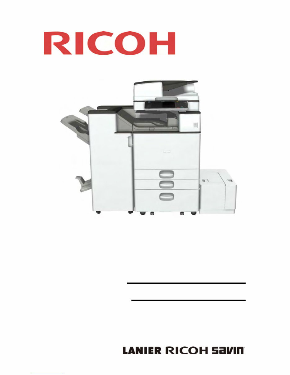
SERVICE MANUAL
D197/D198/D199/
D200/D201/D202
Downloaded from www.Manualslib.com manuals search engine

It is the reader's responsibility when discussing the information contained
within this document to maintain a level of confidentiality that is in the best
interest of Ricoh Americas Corporation and its member companies.
NO PART OF THIS DOCUMENT MAY BE REPRODUCED IN ANY
FASHION AND DISTRIBUTED WITHOUT THE PRIOR
PERMISSION OF RICOH AMERICAS CORPORATION.
All product names, domain names or product illustrations, including
desktop images, used in this document are trademarks, registered
trademarks or the property of their respective companies.
They are used throughout this book in an informational or editorial fashion
only and for the benefit of such companies. No such use, or the use of
any trade name, or web site is intended to convey endorsement or other
affiliation with Ricoh products.
2014 RICOH Americas Corporation. All rights reserved.
Downloaded from www.Manualslib.com manuals search engine

The Service Manual contains information
regarding service techniques, procedures,
processes and spare parts of office equipment
distributed by Ricoh Americas Corporation.
Users of this manual should be either service
trained or certified by successfully completing a
Ricoh Technical Training Program.
Untrained and uncertified users utilizing
information contained in this service manual to
repair or modify Ricoh equipment risk personal
injury, damage to property or loss of warranty
protection.
Ricoh Americas Corporation
WARNING
Downloaded from www.Manualslib.com manuals search engine

LEGEND
PRODUCT
CODE
COMPANY
LANIER RICOH SAVIN
D197 MP 2554SP MP 2554SP MP 2554SP
D198 MP 3054SP MP 3054SP MP 3054SP
D199 MP 3554SP MP 3554SP MP 3554SP
D200 MP 4054SP MP 4054SP MP 4054SP
D201 MP 5054SP MP 5054SP MP 5054SP
D202 MP 6054SP MP 6054SP MP 6054SP
DOCUMENTATION HISTORY
REV. NO. DATE COMMENTS
* 11/2014 Original Printing
Downloaded from www.Manualslib.com manuals search engine

SM i D197/D198/D199/D200/D201/D202
D197/D198/D199/D200/D201/D202
TABLE OF CONTENTS
1. PRODUCT INFORMATION ........................................................... 1-1
1.1 PRODUCT OVERVIEW ............................................................................. 1-1
1.1.1 COMPONENT LAYOUT ................................................................... 1-1
1.1.2 PAPER PATH ................................................................................... 1-3
1.1.3 DRIVE LAYOUT ............................................................................... 1-6
1.1.4 PARTS LAYOUT .............................................................................. 1-8
Scanner Unit ........................................................................................ 1-8
Paper Feed Unit ................................................................................... 1-9
Laser Unit/ PCDU............................................................................... 1-10
Fusing Unit ......................................................................................... 1-11
Waste Toner Bottle............................................................................. 1-12
Duplex/Bypass Unit ............................................................................ 1-13
Paper Exit/ Reverse Unit .................................................................... 1-14
Air Flow .............................................................................................. 1-15
Drive Unit ........................................................................................... 1-16
Electrical Component ......................................................................... 1-17
1.2 MACHINE CODES AND PERIPHERALS CONFIGURATION ................. 1-18
1.2.1 SYSTEM CONFIGURATION AND OPTIONS ................................ 1-18
D197/D198/D199 (NA) ....................................................................... 1-18
D200/D201 (NA) ................................................................................. 1-20
D202 (NA) .......................................................................................... 1-22
D197/D198/D199 (EU) ....................................................................... 1-24
D200/D201 (EU) ................................................................................. 1-26
D202 (EU) .......................................................................................... 1-28
D197/D198/D199 (Asia) ..................................................................... 1-30
D200/D201 (Asia) ............................................................................... 1-32
D202 (Asia) ........................................................................................ 1-33
Guidance for Those Who are Familiar with The Predecessor Product1-35
1.2.2 DIFFERENCES BETWEEN SIMILAR MODELS............................. 1-35
D182/D183 vs. D197/D199 ................................................................ 1-35
D129/D130 vs. D200/D201/D202 ....................................................... 1-36
Differences between D146 Series ...................................................... 1-37
2. INSTALLATION ............................................................................. 2-1
2.1 INSTALLATION REQUIREMENTS ............................................................ 2-1
Downloaded from www.Manualslib.com manuals search engine

D197/D198/D199/D200/D201/D202 ii SM
2.1.1 ENVIRONMENT ............................................................................... 2-1
2.1.2 MACHINE LEVEL ............................................................................. 2-1
2.1.3 MINIMUM SPACE REQUIREMENTS ............................................... 2-1
2.1.4 MACHINE DIMENSIONS.................................................................. 2-2
2.1.5 POWER REQUIREMENTS .............................................................. 2-3
2.2 MAIN MACHINE INSTALLATION .............................................................. 2-4
2.2.1 IMPORTANT NOTICE ON SECURITY ISSUES............................... 2-4
Overview .............................................................................................. 2-4
Password Setting Procedure ................................................................ 2-5
2.2.2 INSTALLATION FLOW CHART........................................................ 2-9
D197/D198/D199.................................................................................. 2-9
D200/D201/D202................................................................................ 2-10
2.2.3 ACCESSORY CHECK .................................................................... 2-11
2.2.4 INSTALLATION PROCEDURE ...................................................... 2-12
Unloading ........................................................................................... 2-12
Tapes and Retainers .......................................................................... 2-12
Toner Bottle........................................................................................ 2-15
Paper Exit Tray Stopper ..................................................................... 2-20
Emblem, Decals ................................................................................. 2-21
Completion ......................................................................................... 2-22
2.2.5 SECURITY SETTINGS ................................................................... 2-22
2.2.6 CHECK IMAGE QUALITY / SETTINGS.......................................... 2-23
Loading Paper .................................................................................... 2-23
Checking the copy image with the test chart ...................................... 2-23
SP Settings ........................................................................................ 2-23
Upper Tray (Size Adjust Tray 1) ......................................................... 2-23
Lower Tray (Size Adjust Tray 2) ......................................................... 2-23
By-Pass Tray (By-Pass Size Detection) ............................................. 2-24
2.2.7 MOVING THE MACHINE................................................................ 2-24
2.2.8 TRANSPORTING THE MACHINE .................................................. 2-25
2.3 PAPER FEED UNIT PB3210/ PB3220 .................................................... 2-26
2.3.1 ACCESSORY CHECK .................................................................... 2-26
2.3.2 INSTALLATION PROCEDURE ...................................................... 2-26
2.4 PAPER FEED UNIT PB3150 ................................................................... 2-32
2.4.1 ACCESSORY CHECK .................................................................... 2-32
2.4.2 INSTALLATION PROCEDURE ...................................................... 2-32
2.5 LCIT PB3170/ PB3230............................................................................. 2-37
2.5.1 ACCESSORY CHECK .................................................................... 2-37
2.5.2 INSTALLATION PROCEDURE ...................................................... 2-37
Downloaded from www.Manualslib.com manuals search engine

SM iii D197/D198/D199/D200/D201/D202
Changing the paper size .................................................................... 2-42
2.6 LCIT RT3030 ........................................................................................... 2-44
2.6.1 ACCESSORY CHECK .................................................................... 2-44
2.6.2 INSTALLATION PROCEDURE ...................................................... 2-44
Changing the Paper Size ................................................................... 2-50
2.7 CASTER TABLE TYPE M3 ...................................................................... 2-52
2.7.1 ACCESSORY CHECK .................................................................... 2-52
2.7.2 INSTALLATION PROCEDURE ...................................................... 2-52
For Installing Directly under the Main Machine .................................. 2-53
For Installing under PB3150 ............................................................... 2-54
2.8 PLATEN COVER PN2000 (D700) ........................................................... 2-56
2.8.1 ACCESSORY CHECK .................................................................... 2-56
2.8.2 INSTALLATION PROCEDURE ...................................................... 2-56
2.9 ARDF DF3090 ......................................................................................... 2-59
2.9.1 ACCESSORY CHECK .................................................................... 2-59
2.9.2 INSTALLATION PROCEDURE ...................................................... 2-59
When feeding thin paper .................................................................... 2-63
2.10 SPDF DF3080 .................................................................................... 2-65
2.10.1 ACCESSORY CHECK .............................................................. 2-65
2.10.2 INSTALLATION PROCEDURE ................................................. 2-66
Attaching the SPDF ............................................................................ 2-66
Attaching the Sub IPU ........................................................................ 2-68
Adjust SP Settings.............................................................................. 2-73
2.11 BRIDGE UNIT BU3070 ...................................................................... 2-74
2.11.1 ACCESSORY CHECK .............................................................. 2-74
2.11.2 INSTALLATION PROCEDURE ................................................. 2-74
2.12 1 BIN TRAY BN3110 .......................................................................... 2-78
2.12.1 ACCESSORY CHECK .............................................................. 2-78
2.12.2 INSTALLATION PROCEDURE ................................................. 2-78
2.13 INTERNAL SHIFT TRAY SH3070 ...................................................... 2-85
2.13.1 ACCESSORY CHECK .............................................................. 2-85
2.13.2 INSTALLATION PROCEDURE ................................................. 2-85
2.14 SIDE TRAY TYPE M3 ........................................................................ 2-90
2.14.1 ACCESSORY CHECK .............................................................. 2-90
2.14.2 INSTALLATION PROCEDURE ................................................. 2-91
2.15 BOOKLET FINISHER SR3170 / FINISHER SR3160 ......................... 2-94
2.15.1 ACCESSORY CHECK .............................................................. 2-94
Booklet Finisher SR3170 (D688) / Finisher SR3160 (D689) .............. 2-94
2.15.2 INSTALLATION PROCEDURE ................................................. 2-95
Downloaded from www.Manualslib.com manuals search engine

D197/D198/D199/D200/D201/D202 iv SM
2.15.3 ADJUSTMENT AFTER INSTALLING THE FINISHER ............ 2-101
How to Check and Adjust the Side-to-Side Registration .................. 2-101
2.15.4 AUXILIARY TRAY ................................................................... 2-102
2.16 PUNCH UNIT PU3060 ..................................................................... 2-103
2.16.1 ACCESSORY CHECK ............................................................ 2-103
2.16.2 INSTALLATION PROCEDURE ............................................... 2-104
2.17 BOOKLET FINISHER SR3150 / FINISHER SR3140 ....................... 2-114
2.17.1 ACCESSORY CHECK ............................................................ 2-114
Booklet Finisher SR3150 / Finisher SR3140 .................................... 2-114
2.17.2 INSTALLATION PROCEDURE ............................................... 2-115
SR3150 ............................................................................................ 2-118
SR3140 ............................................................................................ 2-118
2.17.3 ADJUSTMENT AFTER INSTALLING FINISHER .................... 2-120
How to Check and Adjust the Side-to-Side Registration .................. 2-120
2.18 PUNCH UNIT PU3050 ..................................................................... 2-121
2.18.1 COMPONENT CHECK ........................................................... 2-121
2.18.2 INSTALLATION PROCEDURE ............................................... 2-122
2.19 INTERNAL FINISHER SR3180 ........................................................ 2-134
2.19.1 ACCESSORY CHECK ............................................................ 2-134
2.19.2 INSTALLATION PROCEDURE ............................................... 2-135
Staple Setting as an Initial Setting.................................................... 2-144
2.20 INTERNAL FINISHER SR3130 ........................................................ 2-146
2.20.1 ACCESSORY CHECK ............................................................ 2-146
2.20.2 INSTALLATION PROCEDURE ............................................... 2-146
2.21 PUNCH UNIT PU3040 ..................................................................... 2-155
2.21.1 ACCESSORY CHECK ............................................................ 2-155
2.21.2 INSTALLATION PROCEDURE ............................................... 2-156
2.22 SMART OPERATION PANEL TYPE M3 .......................................... 2-161
2.22.1 ACCESSORY CHECK ............................................................ 2-161
2.22.2 INSTALLATION PROCEDURE ............................................... 2-161
2.23 ANTI-CONDENSATION HEATER TYPE M12 ................................. 2-165
2.23.1 ACCESSORY CHECK ............................................................ 2-165
2.23.2 INSTALLATION PROCEDURE ............................................... 2-166
Anti-Condensation Heater (Scanner) ............................................... 2-166
Anti-Condensation Heater (PCU) ..................................................... 2-176
2.24 ANTI-CONDENSATION HEATER FOR TRAYS .............................. 2-180
2.24.1 ACCESSORY CHECK ............................................................ 2-180
2.24.2 INSTALLATION PROCEDURE ............................................... 2-181
Anti-Condensation Heater for Paper Feed Tray (Main Unit)............. 2-181
Downloaded from www.Manualslib.com manuals search engine

SM v D197/D198/D199/D200/D201/D202
Anti-Condensation Heater for Paper Feed Unit PB3210 / PB3220 .. 2-188
Anti-Condensation Heater for Paper Feed Unit PB3150 .................. 2-190
Anti-Condensation Heater for LCIT PB3170/ PB3230 ...................... 2-192
2.25 CARD READER BRACKET TYPE 3352 .......................................... 2-195
2.25.1 ACCESSORY CHECK ............................................................ 2-195
2.25.2 INSTALLATION PROCEDURE ............................................... 2-196
Scanner Right Cover ........................................................................ 2-198
Upper Rear Cover ............................................................................ 2-198
2.26 KEY COUNTER BRACKET TYPE M3 ............................................. 2-199
2.26.1 ACCESSORY CHECK ............................................................ 2-199
2.26.2 INSTALLATION PROCEDURE ............................................... 2-199
2.27 OPTIONAL COUNTER INTERFACE UNIT TYPE M12 .................... 2-203
2.27.1 ACCESSORY CHECK ............................................................ 2-203
2.27.2 INSTALLATION PROCEDURE ............................................... 2-203
2.28 SMART CARD READER BUILT-IN UNIT TYPE M12 ...................... 2-206
2.28.1 ACCESSORY CHECK ............................................................ 2-206
2.28.2 INSTALLATION PROCEDURE ............................................... 2-207
2.29 INTERNAL OPTIONS ...................................................................... 2-215
2.29.1 LIST OF SLOTS ...................................................................... 2-215
2.30 PRINTER/SCANNER UNIT TYPE M12 ........................................... 2-216
2.30.1 COMPONENT CHECK ........................................................... 2-216
2.30.2 INSTALLATION PROCEDURE ............................................... 2-217
2.31 IEEE 1284 INTERFACE BOARD TYPE A ....................................... 2-221
2.31.1 COMPONENT CHECK ........................................................... 2-221
2.31.2 INSTALLATION....................................................................... 2-222
2.32 IEEE 802.11A/G/N INTERFACE UNIT TYPE M2............................. 2-223
2.32.1 ACCESSORY CHECK ............................................................ 2-223
2.32.2 INSTALLATION....................................................................... 2-224
2.32.3 USER TOOL SETTINGS FOR IEEE 802.11A/G/N ................. 2-226
SP Mode Settings for IEEE 802.11 Wireless LAN ............................ 2-228
2.33 BLUETOOTH INTERFACE UNIT TYPE D ....................................... 2-229
2.33.1 COMPONENT CHECK ........................................................... 2-229
2.33.2 INSTALLATION PROCEDURE ............................................... 2-229
2.34 FILE FORMAT CONVERTER TYPE E ............................................ 2-230
2.34.1 COMPONENT CHECK ........................................................... 2-230
2.34.2 INSTALLATION....................................................................... 2-230
2.35 USB DEVICE SERVER OPTION TYPE M12 ................................... 2-232
2.35.1 COMPONENT CHECK ........................................................... 2-232
Interface Board Surface ................................................................... 2-232
Downloaded from www.Manualslib.com manuals search engine

D197/D198/D199/D200/D201/D202 vi SM
2.35.2 INSTALLATION PROCEDURE ............................................... 2-233
What Do the LED Indications Mean? ............................................... 2-236
Notes for Energy Save Mode Setting ............................................... 2-236
2.35.3 IP ADDRESS SETTING .......................................................... 2-237
2.36 COPY DATA SECURITY UNIT TYPE G .......................................... 2-239
2.36.1 COMPONENT CHECK ........................................................... 2-239
2.36.2 INSTALLATION....................................................................... 2-239
User Tool Setting.............................................................................. 2-241
2.37 HARD DISK DRIVE OPTION TYPE M12 ......................................... 2-242
2.37.1 ACCESSORY CHECK ............................................................ 2-242
2.37.2 INSTALLATION....................................................................... 2-243
2.38 SD CARD OPTION .......................................................................... 2-245
2.38.1 SD CARD SLOTS ................................................................... 2-245
2.38.2 LIST OF SLOTS USED ........................................................... 2-246
2.39 SD CARD APPLI MOVE .................................................................. 2-247
2.39.1 OVERVIEW ............................................................................. 2-247
2.39.2 MOVE EXEC ........................................................................... 2-247
2.39.3 UNDO EXEC ........................................................................... 2-248
2.40 OCR UNIT TYPE M2........................................................................ 2-249
2.40.1 ACCESSORY CHECK ............................................................ 2-249
2.40.2 INSTALLATION PROCEDURE ............................................... 2-249
2.40.3 RECOVERY PROCEDURE .................................................... 2-252
2.41 BROWSER UNIT TYPE M12 ........................................................... 2-253
2.41.1 COMPONENT CHECK ........................................................... 2-253
2.41.2 INSTALLATION PROCEDURE ............................................... 2-253
To update EXJS ............................................................................... 2-255
When checking the version of EXJS ................................................ 2-256
Browser unit uninstallation procedure .............................................. 2-257
2.41.3 SETTINGS .............................................................................. 2-257
Browser default setting ..................................................................... 2-257
2.42 SD CARD FOR NETWARE PRINTING TYPE M12 ......................... 2-258
2.42.1 COMPONENT CHECK ........................................................... 2-258
2.42.2 INSTALLATION PROCEDURE ............................................... 2-258
2.43 POSTSCRIPT3 UNIT TYPE M12 ..................................................... 2-260
2.43.1 COMPONENT CHECK ........................................................... 2-260
2.43.2 INSTALLATION PROCEDURE ............................................... 2-260
2.44 XPS DIRECT PRINT OPTION TYPE M12 ....................................... 2-262
2.44.1 COMPONENT CHECK ........................................................... 2-262
2.44.2 INSTALLATION PROCEDURE ............................................... 2-262
Downloaded from www.Manualslib.com manuals search engine
You're Reading a Preview
What's Included?
 Lifetime Access
Fast Download Speeds
Online & Offline Access
Access PDF Contents & Bookmarks
Full Search Facility
Print one or all pages of your manual
$35.99
Ricoh Aficio MP2554SP, MP3054SP, MP3554SP, MP4054SP, MP5054SP, MP6054SP (product code D197 D198 D199 D200 D201 D202) Field Servi
Viewed 74 Times Today

What's Included?
Lifetime Access
Fast Download Speeds
Online & Offline Access
Access PDF Contents & Bookmarks
Full Search Facility
Print one or all pages of your manual
$35.99

Secure transaction
What's Included?
Lifetime Access
Fast Download Speeds
Online & Offline Access
Access PDF Contents & Bookmarks
Full Search Facility
Print one or all pages of your manual
Description
This Field Service Manual is an essential resource for diagnosing and repairing the Ricoh Aficio MP2554SP, MP3054SP, MP3554SP, MP4054SP, MP5054SP, MP6054SP copier. It contains detailed diagrams, pictures, and comprehensive procedures for both professional mechanics and DIY enthusiasts. The manual covers a wide range of topics including:
- Important Safety Notices
- Product Information such as Component Layout, Paper Path, and Drive Layout
- Installation Requirements and Procedure
- Preventive Maintenance Tables and Procedures
- Replacement and Adjustment Guidelines for various components
- System Maintenance including Service Program Mode and Firmware Update
- Troubleshooting with Self-Diagnostic Mode and Service Call Codes
- Energy Saving features and practices
This comprehensive manual consists of 1348 pages and is available in PDF format, providing the flexibility to print, zoom, or read any section as needed. It is a valuable tool for maintaining and servicing the Ricoh Aficio MP series photocopiers.


