

TOSHIBA e-STUDIO350/450 Service Manual
What's Included?
Fast Download Speeds
Online & Offline Access
Access PDF Contents & Bookmarks
Full Search Facility
Print one or all pages of your manual

SERVICE HANDBOOK
MULTIFUNCTIONAL DIGITAL SYSTEMS
e-STUDIO350/352/450/452
File No. SHE030005J0
R03092141301-TTEC
Ver10_2006-06

Trademarks
• The official name of Windows 95 is Microsoft Windows 95 Operating System.
• The official name of Windows 98 is Microsoft Windows 98 Operating System.
• The official name of Windows Me is Microsoft Windows Millennium Edition Operating System.
• The official name of Windows 2000 is Microsoft Windows 2000 Operating System.
• The official name of Windows XP is Microsoft Windows XP Operating System.
• Microsoft, Windows, Windows NT and the brand names and product names of other Microsoft prod-
ucts are trademarks or registered trademarks of Microsoft Corporation in the U.S. and/or other coun-
tries.
• Apple, AppleTalk, Macintosh, and Mac are trademarks of Apple Computer, Inc. in the U.S. and other
countries.
• PostScript is a trademark of Adobe Systems Incorporated.
• NOVELL, NetWare, and NDS are trademarks or registered trademarks of Novell, Inc.
• Molykote is a registered trademark of Dow Corning Corporation.
• Other company names and product names in this manual are the trademarks of their respective
companies.
© 2003 TOSHIBA TEC CORPORATION All rights reserved
Under the copyright laws, this manual cannot be reproduced in any form without prior written permission
of TOSHIBA TEC CORPORATION. No patent liability is assumed, however, with respect to the use of the
information contained herein.
GENERAL PRECAUTIONS REGARDING THE INSTALLATION
AND SERVICE FOR e-STUDIO350/352/450/452
The installation and service should be done by a qualified service
technician.
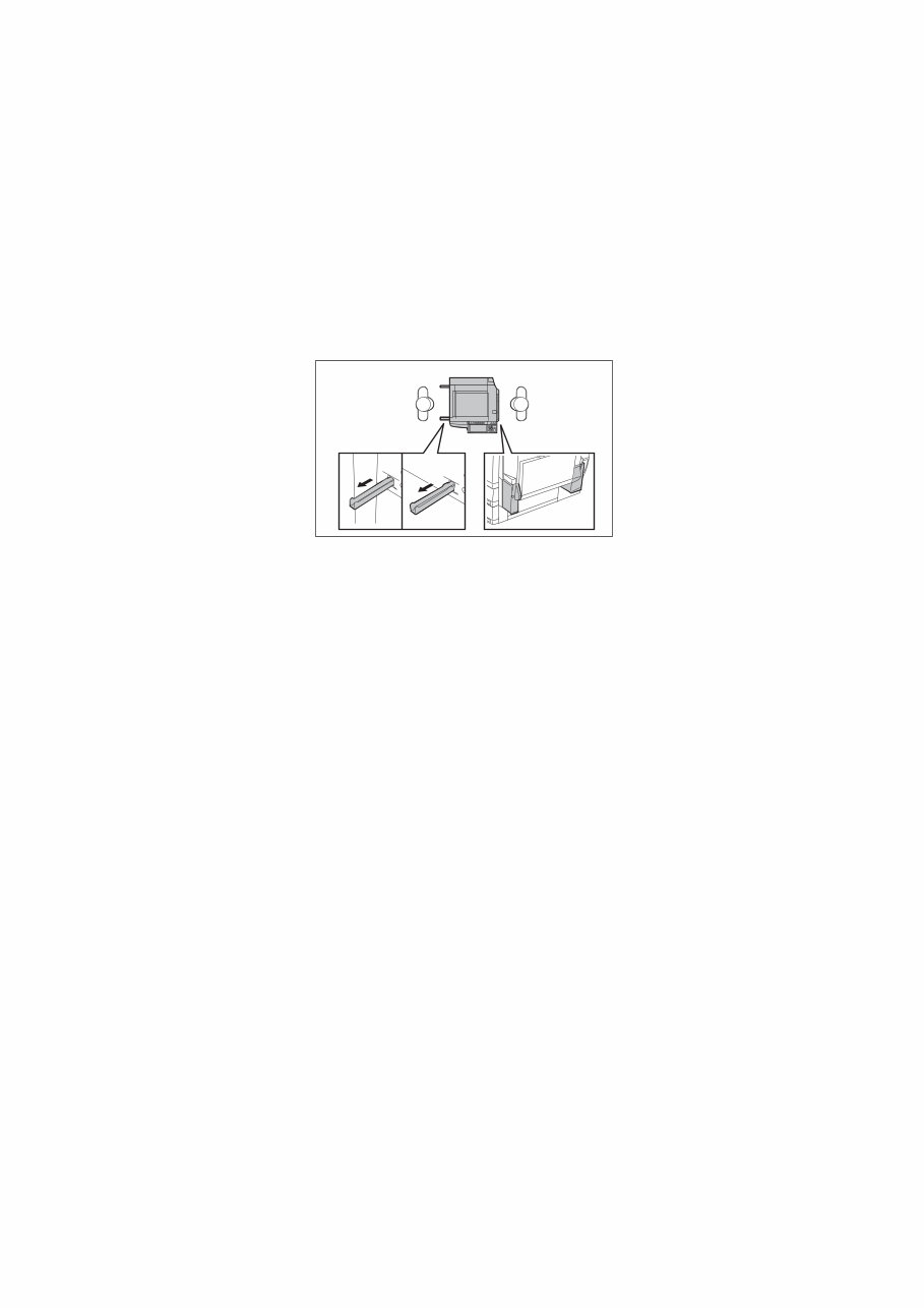
1) Transportation / Installation
- When transporting/installing the equipment, employ two persons and be sure to use the positions
as indicated below.
The equipment is quite heavy and weighs approximately 83kg (182.98 lb.): e-STUDIO350/450 /
86kg (189.59 lb.): e-STUDIO352/452 therefore pay fullattention when handling it.
- Be sure not to hold the movable parts or units (e.g. the control panel, ADU or RADF) when trans-
porting the equipment.
- Be sure to use a dedicated outlet with AC 110V/13.2A, 115V or 127V / 12A, 220-240V or 240V /
8A for its power source.
- The equipment must be grounded for safety.
Never ground it to a gas pipe or a water pipe.
- Select a suitable place for installation.
Avoid excessive heat, high humidity, dust, vibration and direct sunlight.
- Also provide proper ventilation as the equipment emits a slight amount of ozone.
- To insure adequate working space for the copying operation, keep a minimum clearance of 80
cm (32”) on the left, 80 cm (32”) on the right and 10 cm (4”) in the rear.
- The socket-outlet shall be installed near the equipment and shall be easily accessible.
- Be sure to fix and plug in the power cable securely after the installation so that no one trips over
it.
05/11

2) Service of Machines
- Basically, be sure to turn the main switch off and unplug the power cord during service.
- Be sure not to touch high-temperature sections such as the exposure lamp, the fuser unit, the
damp heater and their periphery.
- Be sure not to touch high-voltage sections such as the chargers, developer, IH control circuit,
high-voltage transformer, exposure lamp control inverter, inverter for the LCD backlight and
power supply unit. Especially, the board of these components should not be touched since the
electric charge may remain in the capacitors, etc. on them even after the power is turned OFF.
- Be sure not to touch rotating/operating sections such as gears, belts, pulleys, fan, etc.
- Be careful when removing the covers since there might be the parts with very sharp edges
underneath.
- When servicing the machines with the power turned ON, be sure not to touch live sections and
rotating/operating sections. Avoid exposure to laser radiation.
- Use suitable measuring instruments and tools.
- Avoid exposure to laser radiation during servicing.
Avoid direct exposure to the beam.Do not insert tools, parts, etc. that are reflective into the path
of the laser beam.Remove all watches, rings, bracelets, etc. that are reflective.
- Unplug the power cable and clean the area around the prongs of the plug once a year or more.
A fire may occur when dust lies on this area.
3) Main Service Parts for Safety
- The breaker, door switch, fuse, thermostat, thermofuse, thermistor, etc. are particularly important
for safety. Be sure to handle/install them properly. If these parts are shorted circuit and/or made
their functions out, they may burn down, for instance, and may result in fatal accidents. Do not
allow a short circuit to occur. Do not use the parts not recommended by Toshiba TEC Corpora-
tion.
4) Cautionary Labels
- During servicing, be sure to check the rating plate and the cautionary labels such as “Unplug the
power cord during service”, “Hot area”, “Laser warning label” etc. to see if there is any dirt on
their surface and whether they are properly stuck to the equipment.
5) Disposition of Consumable Parts, Packing Materials, Used batteries and RAM-ICs
- Regarding the recovery and disposal of the equipment, supplies, consumable parts, packing
materials, used batteries and RAM-ICs including lithium batteries, follow the relevant local regu-
lations or rules.
6) When parts are disassembled, reassembly is basically the reverse of disassembly unless
otherwise noted in this manual or other related documents. Be careful not to reassemble
small parts such as screws, washers, pins, E-rings, star washers in the wrong places.
7) Basically, the machine should not be operated with any parts removed or disassembled.
8) Precautions Against Static Electricity
- The PC board must be stored in an anti-electrostatic bag and handled carefully using a wrist-
band, because the ICs on it may become damaged due to static electricity.
Caution: Before using the wristband, pull out the power cord plug of the equipment and
make sure that there are no uninsulated charged objects in the vicinity.
Caution:
Dispose of used batteries and RAM-ICs including lithium batteries according to this manual.
Attention:
Se débarrasser de batteries et RAM-ICs usés y compris les batteries en lithium selon ce manuel.
Vorsicht:
Entsorgung der gebrauchten Batterien und RAM-ICs (inklusive der Lithium-Batterie) nach diesem Handbuch.
05/11

November 2003 © TOSHIBA TEC e-STUDIO350/352/450/452 CONTENTS
1
CONTENTS
e-STUDIO350/352/450/452
1. SPECIFICATIONS / ACCESSORIES / OPTIONS / SUPPLIES .................................. 1-1
1.1 Specifications....................................................................................................................... 1-1
1.2 Accessories ......................................................................................................................... 1-4
1.3 Options ................................................................................................................................ 1-5
1.3.1 e-STUDIO350/450.................................................................................................... 1-5
1.3.2 e-STUDIO352/452.................................................................................................... 1-6
1.4 Supplies ............................................................................................................................... 1-7
1.5 System List .......................................................................................................................... 1-8
1.5.1 e-STUDIO350/450.................................................................................................... 1-8
1.5.2 e-STUDIO352/452.................................................................................................... 1-9
2. ERROR CODE AND SELF-DIAGNOSTIC MODE ........................................................ 2-1
2.1 Error Code List..................................................................................................................... 2-1
2.1.1 Jam........................................................................................................................... 2-1
2.1.2 Service call ............................................................................................................... 2-7
2.1.3 Error in Internet FAX / Scanning Function.............................................................. 2-13
2.1.4 Printer function error ............................................................................................... 2-22
2.2 Self-diagnosis Modes ........................................................................................................ 2-25
2.2.1 Input check (Test mode 03) (e-STUDIO350/450)................................................... 2-27
2.2.2 Input check (Test mode 03) (e-STUDIO352/452)................................................... 2-34
2.2.3 Output check (test mode 03) .................................................................................. 2-42
2.2.4 Test print mode (test mode 04) .............................................................................. 2-45
2.2.5 Adjustment mode (05) (e-STUDIO350/450) ........................................................... 2-46
2.2.6 Adjustment mode (05) (e-STUDIO352/452) ........................................................... 2-64
2.2.7 Setting mode (08) (e-STUDIO350/450) .................................................................. 2-82
2.2.8 Setting mode (08) (e-STUDIO352/452) ................................................................ 2-144
2.2.9 Pixel counter ......................................................................................................... 2-223
2.2.10 Classification List of Adjustment Mode (05) /
Setting Mode (08) (e-STUDIO350/450) ................................................................ 2-231
2.2.11 Classification List of Adjustment Mode (05) /
Setting Mode (08) (e-STUDIO352/452) ................................................................ 2-238
3. ADJUSTMENT .............................................................................................................. 3-1
3.1 Adjustment of Auto-Toner Sensor ....................................................................................... 3-1
3.2 Image Dimensional Adjustment ........................................................................................... 3-3
3.2.1 General description .................................................................................................. 3-3
3.2.2 Paper alignment at the registration roller ................................................................. 3-5
3.2.3 Printer related adjustment ........................................................................................ 3-7
3.2.4 Scanner related adjustment ................................................................................... 3-12
3.3 Image Quality Adjustment (Copying Function) .................................................................. 3-21
3.3.1 Density adjustment ................................................................................................. 3-21
3.3.2 Gamma slope adjustment ...................................................................................... 3-22
3.3.3 Sharpness adjustment ............................................................................................ 3-22
3.3.4 Setting range correction ......................................................................................... 3-23
3.3.5 Setting range correction (Adjustment of background peak) ................................... 3-23
3.3.6 Adjustment of smudged/faint text ........................................................................... 3-24
3.3.7 Gamma balance adjustment < e-STUDIO 352/452 > ............................................ 3-24
3.4 Image Quality Adjustment (Printing Function) ................................................................... 3-25
3.4.1 Adjustment of smudged/faint text ........................................................................... 3-25
3.4.2 Adjustment of image density .................................................................................. 3-25
3.5 Image Quality Adjustment (Scanning Function) ................................................................ 3-26
3.5.1 Density adjustment ................................................................................................. 3-26
3.5.2 Sharpness adjustment ............................................................................................ 3-27
05/12

e-STUDIO350/352/450/452 CONTENTS November 2003 © TOSHIBA TEC
2
3.5.3 Setting range correction ......................................................................................... 3-28
3.5.4 Setting range correction (Adjustment of background peak) ................................... 3-28
3.6 Adjustment of High-Voltage Transformer .......................................................................... 3-29
3.6.1 Adjustment ............................................................................................................. 3-29
3.6.2 Precautions ............................................................................................................ 3-38
3.7 Adjustment of the Scanner Section ................................................................................... 3-40
3.7.1 Carriages ................................................................................................................ 3-40
3.7.2 Lens unit ................................................................................................................. 3-45
3.8 Adjustment of the Paper Feeding System ......................................................................... 3-48
3.8.1 Sheet sideways deviation caused by paper feeding .............................................. 3-48
3.9 Adjustment of Developer Unit ............................................................................................ 3-49
3.9.1 Doctor-to-sleeve gap .............................................................................................. 3-49
3.10 Adjustment of the RADF (MR-3015) .................................................................................. 3-52
3.10.1 Adjustment of RADF position ................................................................................. 3-52
3.10.2 Adjustment of RADF height .................................................................................... 3-57
3.10.3 Adjustment of skew ................................................................................................ 3-59
3.10.4 Automatic adjustment of sensors and initialization of EEPROM ............................ 3-60
3.10.5 Adjustment of aligning ............................................................................................ 3-61
3.10.6 Adjustment of aligning at reversing ........................................................................ 3-62
3.10.7 Adjustment of reverse solenoid .............................................................................. 3-63
3.10.8 Adjustment of RADF opening/closing switch.......................................................... 3-65
3.10.9 Adjustment of RADF opening/closing sensor ......................................................... 3-66
3.10.10Adjustment of tray volume ..................................................................................... 3-67
3.11 Adjustment of the RADF (MR-3018) .................................................................................. 3-68
3.11.1 Adjustment of RADF Position ................................................................................. 3-68
3.11.2 Adjustment of RADF Height ................................................................................... 3-73
3.11.3 Adjustment of Skew................................................................................................ 3-75
3.11.4 Adjustment of the Leading Edge Position .............................................................. 3-78
3.11.5 Adjustment of Horizontal Position .......................................................................... 3-79
3.11.6 Adjustment of Copy Ratio....................................................................................... 3-81
3.11.7 Adjustment of RADF Opening/Closing Sensor ....................................................... 3-82
3.12 Adjustment of the Finisher (MJ-1022)................................................................................ 3-83
3.12.1 Adjusting the jogging plate width ............................................................................ 3-83
3.12.2 Adjusting the angle of the jogging plate ................................................................. 3-85
3.12.3 Adjusting the overlap of the sensor flag ................................................................. 3-86
3.12.4 Adjusting the tension of the stack processing motor belt ....................................... 3-87
3.12.5 Releasing the stack tray guide lever fixing plate .................................................... 3-89
3.12.6 Adjustment of the upper tray angle ........................................................................ 3-90
3.12.7 DIP switch functions ............................................................................................... 3-92
3.13 Adjustment of the Finisher (MJ-1023/1024)....................................................................... 3-93
3.13.1 Adjusting the alignment position (Finisher unit) ...................................................... 3-93
3.13.2 Adjusting the staple position (Finisher unit) ............................................................ 3-94
3.13.3 Adjusting the folding position (Saddle stitcher unit) ................................................ 3-96
3.13.4 Fine adjustment of binding/folding position (Saddle stitcher unit) .......................... 3-98
3.13.5 Sensor output adjustment (Puncher unit) ............................................................... 3-99
3.13.6 Registering the number of punch holes (Puncher unit) ........................................ 3-100
3.14 Adjustment of the Finisher (MJ-1101).............................................................................. 3-101
3.14.1 Adjusting the Alignment Position .......................................................................... 3-101
3.14.2 Adjusting the Stapling Position ............................................................................. 3-103
3.14.3 Stopping Position Adjustment (Puncher unit) ....................................................... 3-105
3.15 Key Copy Counter (MU-8, MU-10) .................................................................................. 3-107
3.16 Adjustment of Dogleg ...................................................................................................... 3-109
4. PREVENTIVE MAINTENANCE (PM) ............................................................................ 4-1
4.1 PM Support Mode ................................................................................................................ 4-1
4.1.1 General description .................................................................................................. 4-1
06/01

November 2003 © TOSHIBA TEC e-STUDIO350/352/450/452 CONTENTS
3
4.1.2 Operational flow and operational screen .................................................................. 4-1
4.1.3 Work flow of parts replacement ................................................................................ 4-6
4.2 General Descriptions for PM Procedure (Maintenance Performed Every 120,000
Output Pages (e-STUDIO350/352) and 150,000 Output Pages (e-STUDIO450/452)) ....... 4-7
4.3 Operational Items in Overhauling ........................................................................................ 4-8
4.4 Cleaning the Units which Have Processed 60,000 Output Pages (e-STUDIO350/352) and
75,000 Output Pages (e-STUDIO450/452).......................................................................... 4-9
4.5 Preventive Maintenance Checklist..................................................................................... 4-10
4.6 PM KIT ............................................................................................................................... 4-29
4.7 Jig List ............................................................................................................................... 4-30
4.8 Grease List ........................................................................................................................ 4-31
4.9 Precautions for Storing and Handling Supplies ................................................................. 4-32
4.9.1 Precautions for storing TOSHIBA supplies ............................................................ 4-32
4.9.2 Checking and cleaning of photoconductive drum................................................... 4-33
4.9.3 Checking and cleaning of drum cleaning blade...................................................... 4-34
4.9.4 Checking and cleaning of fuser roller and pressure roller ...................................... 4-34
4.9.5 Checking and replacing the cleaning roller ............................................................ 4-35
5. TROUBLESHOOTING .................................................................................................. 5-1
5.1 Diagnosis and Prescription for Each Error Code ................................................................. 5-1
5.1.1 Paper transport jam .................................................................................................. 5-1
5.1.2 Paper misfeeding ................................................................................................... 5-14
5.1.3 Cover open jam ...................................................................................................... 5-21
5.1.4 Transport jam (RADF) ............................................................................................ 5-26
5.1.5 Finisher jam ............................................................................................................ 5-32
5.1.6 Drive system related service call ............................................................................ 5-56
5.1.7 Paper feeding system related service call .............................................................. 5-57
5.1.8 Scanning system related service call ..................................................................... 5-63
5.1.9 Fuser unit related service call ................................................................................. 5-65
5.1.10 Communication related service call ........................................................................ 5-69
5.1.11 RADF related service call (MR-3015) ..................................................................... 5-70
5.1.12 RADF related service call (MR-3018) ..................................................................... 5-71
5.1.13 Laser optical unit related service call (MR-3018) ................................................... 5-71
5.1.14 Finisher related service call .................................................................................... 5-72
5.1.15 Service call for others ............................................................................................. 5-90
5.1.16 Error in Internet FAX / Scanning Function.............................................................. 5-93
5.2 Troubleshooting for the Image ......................................................................................... 5-108
5.3 Replacement of PC Boards and HDD ............................................................................. 5-130
5.3.1 Replacing HDD..................................................................................................... 5-130
5.3.2 Replacing SYS board ........................................................................................... 5-132
5.3.3 Caution when Data overwrite kit (GP-1050/1060) is installed ............................. 5-134
5.3.4 HDD information display....................................................................................... 5-134
6. FIRMWARE UPDATING ............................................................................................... 6-1
6.1 Firmware Updating with Download Jig (e-STUDIO350/450) ............................................... 6-2
6.1.1 PWA-DWNLD-350-JIG2 (48 MB) ............................................................................. 6-4
6.1.2 PWA-DWNLD-350-JIG1 (16 MB) .......................................................................... 6-10
6.1.3 Writing the data to the download jig (PWA-DWNLD-350-JIG) .............................. 6-19
6.1.4 K-PWA-DLM-320.................................................................................................... 6-21
6.2 Firmware Updating with Download Jig (e-STUDIO352/452) ............................................. 6-33
6.2.1 PWA-DWNLD-350-JIG2 (48 MB) ........................................................................... 6-35
6.2.2 Writing the data to the download jig (PWA-DWNLD-350-JIG) ............................... 6-44
6.2.3 K-PWA-DLM-320.................................................................................................... 6-46
6.3 Firmware Updating with FSMS (Field Service Manager) (e-STUDIO350/450) ................ 6-60
6.4 Firmware Updating with USB Storage Device (e-STUDIO350/450) .................................. 6-73
6.5 Firmware Updating with USB Storage Device (e-STUDIO352/452) .................................. 6-85
05/11

e-STUDIO350/352/450/452 CONTENTS November 2003 © TOSHIBA TEC
4
6.6 Appendix .......................................................................................................................... 6-101
6.6.1 e-STUDIO350/450................................................................................................ 6-101
6.6.2 e-STUDIO352/452................................................................................................ 6-102
7. POWER SUPPLY UNIT ................................................................................................ 7-1
7.1 Output Channel ................................................................................................................... 7-1
7.2 Fuse ..................................................................................................................................... 7-3
7.3 Configuration of Power Supply Unit ..................................................................................... 7-4
8. REMOTE SERVICE...................................................................................................... 8-1
8.1 Auto Supply Order ............................................................................................................... 8-1
8.1.1 Outline ...................................................................................................................... 8-1
8.1.2 Setting Item .............................................................................................................. 8-2
8.1.3 Setting procedure ..................................................................................................... 8-4
8.1.4 Order Sheet Format ............................................................................................... 8-11
8.2 Service Notification ............................................................................................................ 8-13
8.2.1 Outline .................................................................................................................... 8-13
8.2.2 Setting .................................................................................................................... 8-13
8.2.3 Items to be notified ................................................................................................. 8-18
9. DATA CLONING with USB STORAGE DEVICE (e-STUDIO352/452) ........................ 9-1
10. WIRE HARNESS CONNECTION DIAGRAMS ........................................................... 10-1
10.1 AC Wire Harness ............................................................................................................... 10-1
10.2 DC Wire Harness (e-STUDIO350/450)...................................................................... Appendix
10.3 Connector Table (e-STUDIO350/450) ....................................................................... Appendix
10.4 DC Wire Harness (e-STUDIO352/452)...................................................................... Appendix
10.5 Connector Table (e-STUDIO352/452) ....................................................................... Appendix
05/11

November 2003 © TOSHIBA TEC e-STUDIO350/352/450/452 SPECIFICATIONS / ACCESSORIES / OPTIONS / SUPPLIES
1 - 1
1
1. SPECIFICATIONS / ACCESSORIES / OPTIONS / SUPPLIES
1.1 Specifications
• Copy process Indirect electrophotographic process (dry)
• Type Desktop type (console type: when paper feed pedestal (PFP) and large
capacity feeder (LCF) are installed)
• Original table Fixed type (the left rear corner used as guide to place originals)
• Accepted originals Sheet, book and 3-dimensional object. The reversing automatic document
feeder (RADF) only accepts paper which are not pasted or stapled.
Carbon paper are not acceptable either.
Maximum size: A3/LD
• Copy speed (Copies/min.)
e-STUDIO350/352
e-STUDIO450/452
* “–” means “Not acceptable”.
* The copy speed in the above table are available when originals are manually placed for single side,
multiple copying.
* When the RADF is used, the copy speed of 35[45] sheets per minute is only available under the fol-
lowing conditions:
• Original/Mode: Single side original/A4/LT size. APS/automatic density are not selected.
• Number of sheets: 35[45] or more.
• Paper feeding: LCF
• Reproduction ratio: 100%
Values in [ ] are for e-STUDIO450/452 in case that the specification is different between e-STUDIO350/352
and e-STUDIO450/452.
Single - sided originals Double - sided originals
MR-3015
50 to 127 g/m
2
(13 lb. Bond to 34 lb. Bond)
50 to 105 g/m
2
(13 lb. Bond to 28 lb. Bond)
MR-3018
35 to 157 g/m
2
(9.3 lb. Bond to 58 lb. Cover)
50 to 157 g/m
2
(13 lb. Bond to 58 lb. Cover)
Paper size
Paper supply
Drawer
Bypass feed
PFP LCF
Size specified
Size not
specified
A4, LT, B5 35 35 18 35 35
A4-R, B5-R, A5-R,
LT-R, ST-R
25 25 18 25 -
B4, LG 21 21 18 21 -
A3, LD 18 18 18 18 -
Paper size
Paper supply
Drawer
Bypass feed
PFP LCF
Size specified
Size not
specified
A4, LT, B5 45 40 21 45 45
A4-R, B5-R, A5-R,
LT-R, ST-R
28 28 21 28 -
B4, LG 24 24 21 24 -
A3, LD 21 21 21 21 -
05/11

e-STUDIO350/352/450/452 SPECIFICATIONS / ACCESSORIES / OPTIONS / SUPPLIES November 2003 © TOSHIBA TEC
1 - 2
* System copy speed
* The system copy speed, including scanning time, is available when 10 sheets of A4/LT size original
are set on RADF and one of the copy modes in the left table is selected. The period of time from
pressing [START] to the paper exit completely out of the equipment based on the actually measured
value.
* Upper drawer is selected and copying is at the non-sort mode.
* Automatic copy density, APS/AMS are turned off.
* Finisher is not installed.
• Copy paper
First copy time ...................... e-STUDIO350/352: Approx. 3.9sec. or less
e-STUDIO450/452: Approx. 3.9sec. or less
(A4/LT, upper drawer, 100%, original placed manually)
Warming-up time .................. Approx. 20 seconds (temperature: 20°C)
Multiple copying.................... Up to 999 copies; Key in set numbers
Reproduction ratio ................ Actual ratio: 100±0.5%
Zooming: 25 to 400% in increments of 1%
(25 to 200% when using RADF)
Resolution/Gradation............ Scanning: 600 dpi x 600 dpi
Printing: Equivalent to 2400 dpi x 600 dpi
Gradation: 256 steps
Eliminated portion................. Leading edges: 3.0±2.0 mm, Side/trailing edges: 2.0±2.0 mm (copy)
Leading / trailing edges: 5.0±2.0 mm, Side edges: 5.0±2.0 mm (print)
Copy mode
Sec.
e-STUDIO350/352 e-STUDIO450/452
Single-sided originals
Single-sided copies
1 set 20.85 17.49
3 sets 57.95 46.68
5 sets 91.20 73.50
Single-sided originals
Double-sided copies
1 set 27.42 25.71
3 sets 62.18 57.41
5 sets 97.55 89.03
Double-sided originals
Double-sided copies
1 set 55.47 54.68
3 sets 126.21 118.07
5 sets 196.93 181.36
Double-sided originals
Single-sided copies
1 set 48.22 48.20
3 sets 117.44 102.18
5 sets 184.96 155.06
Drawer ADU PFP LCF Bypass copy Remarks
Size
A3 to A5-R
LD to ST-R
A4, LT
A3 to A5-R, LD to ST-R
(Non-standard or user-
specified sizes can be set.)
Weight
64 to 105 g/m
2
17 to 28 lb.
64 to 209 g/m
2
, 17 to 55
lb.(Continuous feeding)
50 to 209 g/m
2
, 13 to 55 lb.
(Single paper feeding)
Special
paper
-
Tracing paper, labels,
OHP film (thickness: 80μm
or thicker)
These special paper
recommended
by Toshiba Tec
05/11
You're Reading a Preview
What's Included?
Fast Download Speeds
Online & Offline Access
Access PDF Contents & Bookmarks
Full Search Facility
Print one or all pages of your manual
$28.99
Viewed 42 Times Today


Secure transaction
What's Included?
Fast Download Speeds
Online & Offline Access
Access PDF Contents & Bookmarks
Full Search Facility
Print one or all pages of your manual
$28.99
This service repair manual provides detailed pictures and diagrams, offering complete step-by-step information on repair, servicing, and preventative maintenance for the TOSHIBA e-STUDIO350/450. It is highly detailed to guide both professional mechanics and DIY enthusiasts through every repair and troubleshooting procedure, containing all the necessary information to keep the photocopier in optimal working condition.
By utilizing this manual, you can save on repair costs by performing the maintenance yourself, ultimately becoming an expert in photocopier repair.
- Manual Language: English
- File Format: PDF
- File Delivery: Not Applicable
- Pages: 286


