SERVICE MANUAL MULTIFUNCTIONAL DIGITAL SYSTEMS e-STUDIO200L/202L/230/232/280/282 File No. SME040009D0 R04022142801-TTEC Ver04_2005-11 Downloaded from www.Manualslib.com manuals search engine
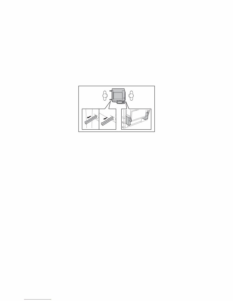
GENERAL PRECAUTIONS REGARDING THE SERVICE FOR e-STUDIO200L/202L/230/232/280/282 SERIES The installation and service should be done by a qualified service technician. 1) Transportation/Installation - When transporting/installing the equipment, employ two persons and be sure to hold the posi- tions as shown in the figure. The equipment is quite heavy and weighs approximately 75 kg (165.34 lb.) therefore pay full attention when handling it. - Be sure not to hold the movable parts or units (e.g. the control panel, ADU or RADF) when trans- porting the equipment. - Be sure to use a dedicated outlet with AC 110 V / 13.2 A, 115 V or 127 V / 12 A, 220-240 V or 240 V / 8 A for its power source. - The equipment must be grounded for safety. - Select a suitable place for installation. Avoid excessive heat, high humidity, dust, vibration and direct sunlight. - Provide proper ventilation since the equipment emits a slight amount of ozone. - To insure adequate working space for the copying operation, keep a minimum clearance of 80 cm (32”) on the left, 80 cm (32”) on the right and 10 cm (4”) on the rear. - The equipment shall be installed near the socket outlet and shall be accessible. - Be sure to fix and plug in the power cable securely after the installation so that no one trips over it. 05/11 Downloaded from www.Manualslib.com manuals search engine
2) General Precautions at Service - Be sure to turn the power OFF and unplug the power cable during service (except for the service should be done with the power turned ON). - Unplug the power cable and clean the area around the prongs of the plug and socket outlet once a year or more. A fire may occur when dust lies on this area. - When the parts are disassembled, reassembly is the reverse of disassembly unless otherwise noted in this manual or other related documents. Be careful not to install small parts such as screws, washers, pins, E-rings, star washers in the wrong places. - Basically, the equipment should not be operated with any parts removed or disassembled. - The PC board must be stored in an anti-electrostatic bag and handled carefully using a wristband since the ICs on it may be damaged due to static electricity. - Avoid expose to laser beam during service. This equipment uses a laser diode. Be sure not to expose your eyes to the laser beam. Do not insert reflecting parts or tools such as a screwdriver on the laser beam path. Remove all reflecting metals such as watches, rings, etc. before starting service. - Be sure not to touch high-temperature sections such as the exposure lamp, fuser unit, damp heater and areas around them. - Be sure not to touch high-voltage sections such as the chargers, developer, high-voltage trans- former, exposure lamp control inverter, inverter for the LCD backlight and power supply unit. Especially, the board of these components should not be touched since the electric charge may remain in the capacitors, etc. on them even after the power is turned OFF. - Make sure that the equipment will not operate before touching potentially dangerous places (e.g. rotating/operating sections such as gears, belts pulleys, fans and laser beam exit of the laser optical unit). - Be careful when removing the covers since there might be the parts with very sharp edges underneath. - When servicing the equipment with the power turned ON, be sure not to touch live sections and rotating/operating sections. Avoid exposing your eyes to laser beam. - Use designated jigs and tools. - Use recommended measuring instruments or equivalents. - Return the equipment to the original state and check the operation when the service is finished. 3) Important Service Parts for Safety - The breaker, door switch, fuse, thermostat, thermofuse, thermistor, IC-RAMs including lithium batteries, etc. are particularly important for safety. Be sure to handle/install them properly. If these parts are short-circuited and their functions become ineffective, they may result in fatal accidents such as burnout. Do not allow a short-circuit or do not use the parts not recommended by Toshiba TEC Corporation. 4) Cautionary Labels - During servicing, be sure to check the rating plate and cautionary labels such as “Unplug the power cable during service”, “CAUTION. HOT”, “CAUTION. HIGH VOLTAGE”, “CAUTION. LASER BEAM”, etc. to see if there is any dirt on their surface and if they are properly stuck to the equipment. Caution: Before using the wristband, unplug the power cable of the equipment and make sure that there are no charged objects which are not insulated in the vicinity. Downloaded from www.Manualslib.com manuals search engine
5) Disposal of the Equipment, Supplies, Packing Materials, Used Batteries and IC-RAMs - Regarding the recovery and disposal of the equipment, supplies, packing materials, used batter- ies and IC-RAMs including lithium batteries, follow the relevant local regulations or rules. Caution: Dispose of used batteries and IC-RAMs including lithium batteries according to this manual. Attention: Se débarrasser de batteries et IC-RAMs usés y compris les batteries en lithium selon ce manuel. Vorsicht: Entsorgung der gebrauchten Batterien und IC-RAMs (inclusive der Lithium-Batterie) nach diesem Handbuch. 05/11 Downloaded from www.Manualslib.com manuals search engine
Downloaded from www.Manualslib.com manuals search engine
This comprehensive service manual is designed to assist in the repair and maintenance of Toshiba e-STUDIO 200L, e-STUDIO 230, e-STUDIO 280, e-STUDIO 202L, e-STUDIO 232, e-STUDIO 282, e-STUDIO 203L, e-STUDIO 233, and e-STUDIO 283 copiers. It contains detailed diagrams, pictures, and procedures for diagnosing and repairing various components of the copier.
Every chapter in this manual is fully detailed and includes simulation codes, trouble codes, maintenance procedures, reset procedures, and diagnose procedures for the copier. It is a valuable resource for both professional mechanics and DIY enthusiasts.
The manual includes the following sections:
SPECIFICATIONS / ACCESSORIES / OPTIONS / SUPPLIES
Specifications
Accessories
Options
Supplies
System List
OUTLINE OF THE MACHINE
Sectional View
Electric Parts Layout
Symbols and Functions of Various Components
General Description
Installation and Replacement of Covers and PC Boards
Installation and Replacement of Options
COPY PROCESS
General Description of Copying Process
Details of Copying Process
Comparison with e-STUDIO350/450
GENERAL OPERATION
Overview of Operation
Description of Operation
Detection of Abnormality
Flow Chart
CONTROL PANEL
Control Panel and Display Panel
Items Shown on the Control Panel
Relation between the Equipment State and Operator's Operation
Description of Operation
Disassembly and Replacement
SCANNER
Function
Construction
Description of Operation
Control of Exposure Lamp
General Description of CCD Control
Automatic Original Size Detection Circuit
Disassembly and Replacement
IMAGE PROCESSING
General Description
Configuration
SLG Board
LGC Board
Laser Driving PC Board
LASER OPTICAL UNIT
General Description
Structure
Laser Diode
Polygonal Motor
Internal cooling fan-2
Disassembly and Replacement
PAPER FEEDING SYSTEM
Functions
Operation
Drive Circuit of Tray-up Motor
Disassembly and Replacement
DRIVE SYSTEM
General Description
Functions
Main Motor
Disassembly and Replacement
DRUM RELATED SECTION
Configuration
Functions
High-Voltage Transformer Output Control Circuit
Drum Temperature Detection Circuit
Temperature/Humidity Detection Circuit
Disassembly and Replacement
DEVELOPMENT SYSTEM
Configuration
Functions
Drive Circuit of Toner Motor
Auto-Toner Circuit
Disassembly and Replacement
FUSER UNIT
General Description
Operation
Functions
Heater Control Circuit
Disassembly and Replacement
PAPER EXIT SECTION
General Description
Functions
Control Circuit of Exit Motor
Exit Motor Drive
Disassembly and Replacement
AUTOMATIC DUPLEXING UNIT (ADU) (OPTION: MD-0102)
General Description
Description of Operations
Drive of ADU
Flow Chart
Disassembly and Replacement
POWER SUPPLY UNIT
Construction
Operation of DC Output Circuits
Output Channel
Fuse
Configuration of Power Supply Unit
Sequence of Power Supply
AC Wire Harness
PC BOARDS
ERROR CODE AND SELF-DIAGNOSTIC MODE
Error Code List
Self-diagnosis Modes
ADJUSTMENT
Adjustment of Auto-Toner Sensor
Image Dimensional Adjustment
Image Quality Adjustment (Copying Function)
Image Quality Adjustment (Printing Function)
Image Quality Adjustment (Scanning Function)
Adjustment of High-Voltage Transformer
Adjustment of the Scanner Section
Adjustment of the Paper Feeding System
Adjustment of Developer Unit
Adjustment of the RADF (MR-3016)
Adjustment of the RADF (MR-3020)
Adjustment of the Finisher (MJ-1022)
Adjustment of the Finisher (MJ-1025)
Key Copy Counter (MU-8, MU-10)
Adjustment of Dogleg
PREVENTIVE MAINTENANCE (PM)
PM Support Mode
General Descriptions for PM Procedure
Operational Items in Overhauling
Preventive Maintenance Checklist
PM KIT
Jig List
Grease List
Precautions for Storing and Handling Supplies
TROUBLESHOOTING
Diagnosis and Prescription for Each Error Code
Troubleshooting for the Image
Replacement of PC Boards and HDD
FIRMWARE UPDATING
REMOTE SERVICE
Auto Supply Order
Service Notification
DATA CLONING with USB STORAGE DEVICE (e-STUDIO 202L/203L/232/233/282/283)
WIRE HARNESS CONNECTION DIAGRAMS
The manual also includes a Service Handbook Manual and a Parts List for the Toshiba e-STUDIO 202L-232-282 copiers, providing comprehensive information for servicing and maintaining these machines.