

Sharp MX-M623N, MX-M623U, MX-M753N, MX-M753U, Service Manual
What's Included?
Fast Download Speeds
Online & Offline Access
Access PDF Contents & Bookmarks
Full Search Facility
Print one or all pages of your manual
SERVICE MANUAL
Parts marked with " " are important for maintaining the safety of the set. Be sure to replace these parts with
specified ones for maintaining the safety and performance of the set.
SHARP CORPORATION
This document has been published to be used
for after sales service only.
The contents are subject to change without notice.
NOTE FOR SERVICING
[1] PRODUCT OUTLINE . . . . . . . . . . . . . . . . . . . . . . . . . . . . . . . . . . . . . . . . . . . . . . . 1-1
[2] SPECIFICATIONS . . . . . . . . . . . . . . . . . . . . . . . . . . . . . . . . . . . . . . . . . . . . . . . . . 2-1
[3] CONSUMABLE PARTS . . . . . . . . . . . . . . . . . . . . . . . . . . . . . . . . . . . . . . . . . . . . . 3-1
[4] EXTERNAL VIEW AND INTERNAL STRUCTURE . . . . . . . . . . . . . . . . . . . . . . . . 4-1
[5] ADJUSTMENTS AND SETTINGS . . . . . . . . . . . . . . . . . . . . . . . . . . . . . . . . . . . . . 5-1
[6] SIMULATION . . . . . . . . . . . . . . . . . . . . . . . . . . . . . . . . . . . . . . . . . . . . . . . . . . . . . 6-1
[7] SELF DIAG AND TROUBLE CODE . . . . . . . . . . . . . . . . . . . . . . . . . . . . . . . . . . . . 7-1
[8] OPERATIONAL DESCRIPTIONS. . . . . . . . . . . . . . . . . . . . . . . . . . . . . . . . . . . . . . 8-1
[9] MAINTENANCE . . . . . . . . . . . . . . . . . . . . . . . . . . . . . . . . . . . . . . . . . . . . . . . . . . . 9-1
[10] DISASSEMBLY AND ASSEMBLY . . . . . . . . . . . . . . . . . . . . . . . . . . . . . . . . . . . . 10-1
[11] FIRMWARE UPDATE . . . . . . . . . . . . . . . . . . . . . . . . . . . . . . . . . . . . . . . . . . . . . . 11-1
[12] ELECTRICAL SECTION. . . . . . . . . . . . . . . . . . . . . . . . . . . . . . . . . . . . . . . . . . . . 12-1
[13] SERVICE WEB PAGE . . . . . . . . . . . . . . . . . . . . . . . . . . . . . . . . . . . . . . . . . . . . . 13-1
TopPage
CONTENTS
CODE: 00ZMXM753/S1E
DIGITAL MULTIFUNCTIONAL
SYSTEM
MX-M623 N/U
MX-M753 N/U MODEL

CONTENTS
NOTE FOR SERVICING
1. Precautions for servicing . . . . . . . . . . . . . . . . . . . . i
2. Warning for servicing . . . . . . . . . . . . . . . . . . . . . . . i
3. Note for installation site . . . . . . . . . . . . . . . . . . . . . i
4. Note for handling PWB and electronic parts . . . . ii
5. Note for repairing/replacing the LSU . . . . . . . . . . iii
6. Note for handling the drum unit,
the transfer unit, the developing unit,
and the fusing unit . . . . . . . . . . . . . . . . . . . . . . . . iii
7. Screw tightening torque . . . . . . . . . . . . . . . . . . . . iii
[1] PRODUCT OUTLINE
1. System configuration . . . . . . . . . . . . . . . . . . . . . 1-1
2. Machine configuration . . . . . . . . . . . . . . . . . . . . 1-1
3. Combination of options. . . . . . . . . . . . . . . . . . . . 1-2
[2] SPECIFICATIONS
1. Basic specifications . . . . . . . . . . . . . . . . . . . . . . 2-1
2. Functional specifications . . . . . . . . . . . . . . . . . . 2-4
[3] CONSUMABLE PARTS
1. Supply system table . . . . . . . . . . . . . . . . . . . . . . 3-1
2. Maintenance parts list . . . . . . . . . . . . . . . . . . . . 3-1
3. Definition of Developer and Drum life end . . . . . 3-3
4. Production number identification . . . . . . . . . . . . 3-3
[4] EXTERNAL VIEW AND INTERNAL STRUCTURE
1. Identification of each section and functions . . . . 4-1
[5] ADJUSTMENTS AND SETTINGS
1. General. . . . . . . . . . . . . . . . . . . . . . . . . . . . . . . . 5-1
2. Adjustment item list . . . . . . . . . . . . . . . . . . . . . . 5-1
3. Details of adjustment . . . . . . . . . . . . . . . . . . . . . 5-2
[6] SIMULATION
1. General (Including basic operations) . . . . . . . . . 6-1
2. List of simulation codes . . . . . . . . . . . . . . . . . . . 6-3
3. Details of simulation . . . . . . . . . . . . . . . . . . . . . . 6-7
[7] SELF DIAG AND TROUBLE CODE
1. Self diag . . . . . . . . . . . . . . . . . . . . . . . . . . . . . . . 7-1
2. Trouble code list . . . . . . . . . . . . . . . . . . . . . . . . . 7-4
3. Details of trouble code . . . . . . . . . . . . . . . . . . . . 7-6
4. Paper JAM code . . . . . . . . . . . . . . . . . . . . . . . . 7-26
5. Necessary works when replacing
the PWB and the HDD . . . . . . . . . . . . . . . . . . . 7-30
[8] OPERATIONAL DESCRIPTIONS
1. Operation panel . . . . . . . . . . . . . . . . . . . . . . . . . 8-1
2. Scanner section . . . . . . . . . . . . . . . . . . . . . . . . . 8-3
3. Manual paper feed section . . . . . . . . . . . . . . . . . 8-5
4. Tray paper feed section . . . . . . . . . . . . . . . . . . . 8-7
5. Paper transport section, Duplex section. . . . . . 8-14
6. LSU section . . . . . . . . . . . . . . . . . . . . . . . . . . . 8-22
7. Photo-conductor section. . . . . . . . . . . . . . . . . . 8-24
8. Toner supply section. . . . . . . . . . . . . . . . . . . . . 8-27
9. Developing section . . . . . . . . . . . . . . . . . . . . . . 8-29
10. Transfer section . . . . . . . . . . . . . . . . . . . . . . . . 8-31
11. Fusing section . . . . . . . . . . . . . . . . . . . . . . . . . 8-33
12. Paper exit section. . . . . . . . . . . . . . . . . . . . . . . 8-36
13. Automatic document feeder . . . . . . . . . . . . . . . 8-38
[9] MAINTENANCE
1. Necessary execution items
(Before and after maintenance) . . . . . . . . . . . . . 9-1
2. Contents of the maintenance codes and
countermeasures
(Relationship between various counter values
and display messages) . . . . . . . . . . . . . . . . . . . 9-2
3. Maintenance system table . . . . . . . . . . . . . . . . . 9-4
[10] DISASSEMBLY AND ASSEMBLY
1. Exterior . . . . . . . . . . . . . . . . . . . . . . . . . . . . . . 10-1
2. Operation panel section . . . . . . . . . . . . . . . . . . 10-2
3. Scanner section . . . . . . . . . . . . . . . . . . . . . . . . 10-5
4. Manual paper feed section . . . . . . . . . . . . . . . 10-9
5. Tray paper feed section . . . . . . . . . . . . . . . . . 10-14
6. Paper transport and duplex section . . . . . . . . 10-23
7. LSU section . . . . . . . . . . . . . . . . . . . . . . . . . . 10-39
8. Photo-conductor section . . . . . . . . . . . . . . . . 10-40
9. Toner supply section . . . . . . . . . . . . . . . . . . . 10-45
10. Developing section . . . . . . . . . . . . . . . . . . . . 10-47
11. Transfer section . . . . . . . . . . . . . . . . . . . . . . . 10-49
12. Fusing section . . . . . . . . . . . . . . . . . . . . . . . . 10-51
13. Paper exit section . . . . . . . . . . . . . . . . . . . . . 10-58
14. Drive section . . . . . . . . . . . . . . . . . . . . . . . . . 10-63
15. PWB section . . . . . . . . . . . . . . . . . . . . . . . . . 10-75
16. Fan section . . . . . . . . . . . . . . . . . . . . . . . . . . 10-80
17. Filter section . . . . . . . . . . . . . . . . . . . . . . . . . 10-85
18. Automatic document feeder . . . . . . . . . . . . . . 10-86
19. Other . . . . . . . . . . . . . . . . . . . . . . . . . . . . . . 10-107
[11] FIRMWARE UPDATE
1. Outline . . . . . . . . . . . . . . . . . . . . . . . . . . . . . . . 11-1
2. Update procedure . . . . . . . . . . . . . . . . . . . . . . 11-1
[12] ELECTRICAL SECTION
1. Block diagram . . . . . . . . . . . . . . . . . . . . . . . . . 12-1
2. Actual wiring chart . . . . . . . . . . . . . . . . . . . . . . 12-9
3. Signal list . . . . . . . . . . . . . . . . . . . . . . . . . . . . 12-21
[13] SERVICE WEB PAGE
1. General . . . . . . . . . . . . . . . . . . . . . . . . . . . . . . 13-1
2. Details and operation procedures . . . . . . . . . . 13-1
MX-M753N NOTE FOR SERVICING - i
MX-M753N
Service Manual NOTE FOR SERVICING
1. Precautions for servicing
1) When servicing, disconnect the power plug, the printer cable,
the network cable, and the telephone line from the machine,
except when performing the communication test, etc.
It may cause an injury or an electric shock.
2) There is a high temperature area inside the machine. Use an
extreme care when servicing.
It may cause a burn.
3) There is a high voltage section inside the machine which may
cause an electric shock. Be careful when servicing.
4) Do not disassemble the laser unit. Do not insert a reflective
material such as a screwdriver in the laser beam path.
It may damage eyes by reflection of laser beams.
5) When servicing with the machine operating, be careful not to
squeeze you hands by the chain, the belt, the gear, and other
driving sections.
6) Do not leave the machine with the cabinet disassembled.
Do not allow any person other than a serviceman to touch
inside the machine. It may cause an electric shock, a burn, or
an injury.
7) When servicing, do not breathe toner, developer, and ink
excessively. Do not get them in the eyes.
If toner, developer, or ink enters your eyes, wash it away with
water immediately, and consult a doctor if necessary.
8) The machine has got sharp edges inside. Be careful not to
damage fingers when servicing.
9) Do not throw toner or a toner cartridge in a fire. Otherwise,
toner may pop and burn you.
10) When replacing the lithium battery of the PWB, use a specified
one only.
If a battery of different specification is used, it may be broken,
causing breakdown or malfunction of the machine.
11) When carrying a unit with PWB or electronic parts installed to
it, be sure to put it in an anti-static-electricity bag.
It may cause a breakdown or malfunctions.
12) When the machine is moved over a bump, hold the grip on the
right side of the machine to lift and cross the bump over.
This is because the casters may be broken for a big bump.
2. Warning for servicing
1) Be sure to connect the power cord only to a power outlet that
meets the specified voltage and current requirements.
Avoid complex wiring, which may lead to a fire or an electric
shock.
It may cause a fire or an electric shock.
2) If there is any abnormality such as a smoke or an abnormal
smell, interrupt the job and disconnect the power plug.
It may cause a fire or an electric shock.
3) Be sure to connect the grounding wire. If an electric leakage
occurs without grounding, a fire or an electric shock may
result.
To protect the machine and the power unit from lightening,
grounding must be made.
4) When connecting the grounding wire, never connect it to the
following points.
It may cause an explosion, a fire or an electric shock.
• Gas tube
• Lightning conductor
• A water pipe or a water faucet, which is not recognized as a
grounding object by the authorities.
• Grounding wire for telephone line
5) Do not damage, break, or work the power cord.
Do not put heavy objects on the power cable. Do not bend it
forcibly or do not pull it extremely.
It may cause a fire or an electric shock.
6) Keep the power cable away from a heat source.
Do not insert the power plug with dust on it into a power outlet.
It may cause a fire or an electric shock.
7) Do not put a receptacle with water in it or a metal piece which
may drop inside the machine.
It may cause a fire or an electric shock.
8) With wet or oily hands, do not touch the power plug, do not
insert the telephone line jack, do not operate the machine, or
do not perform servicing.
It may cause an electric shock.
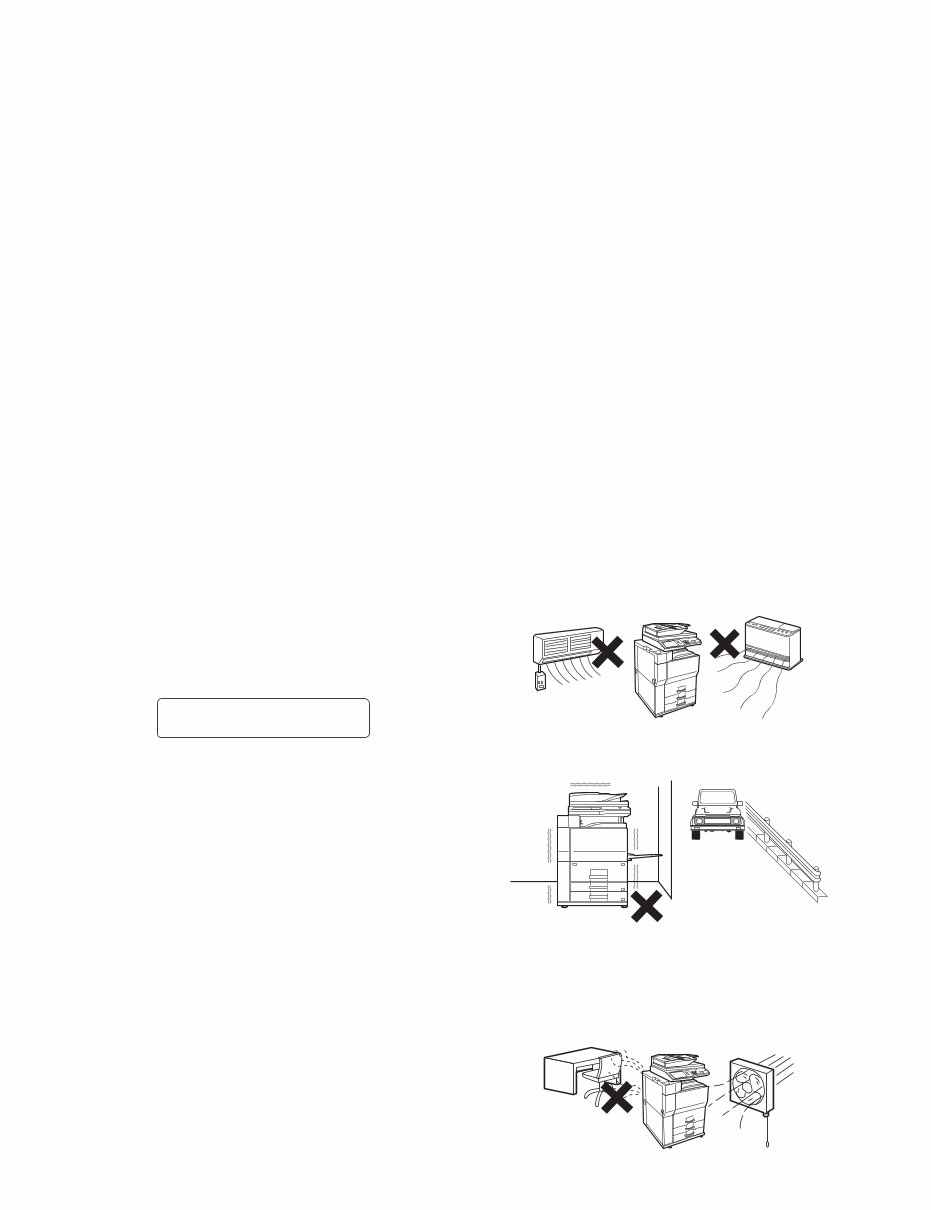
3. Note for installation site
Do not install the machine at the following sites.
1) Place of high temperature, high humidity, low tempera-
ture, low humidity, place under an extreme change in tem-
perature and humidity.
Paper may get damp and form dews inside the machine, caus-
ing paper jam or copy dirt.
For operating and storing conditions, refer to the specifications
described later.
2) Place of much vibrations
It may cause a breakdown.
3) Poorly ventilated place
An electrostatic type copier will produce ozone inside it.
The quantity of ozone produced is designed to a low level so
as not to affect human bodies. However, continuous use of
such a machine may produce a smell of ozone. Install the
machine in a well ventilated place, and ventilate occasionally.
CAUTION
DOUBLE POLE/NEUTRAL FUSING
(200V series only)
MX-M753N NOTE FOR SERVICING - ii
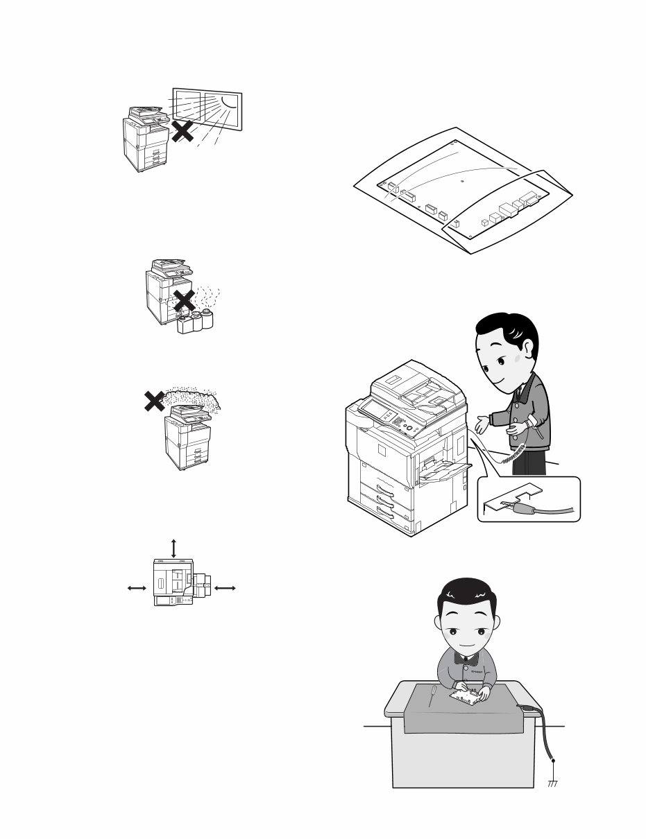
4) Place of direct sunlight.
Plastic parts and ink may be deformed, discolored, or may
undergo qualitative change.
It may cause a breakdown or copy dirt.
5) Place which is full of organic gases such as ammonium
The organic photo-conductor (OPC) drum used in the machine
may undergo qualitative change due to organic gases such as
ammonium.
Installation of this machine near a diazo-type copier may result
in dirt copy.
6) Place of much dust
When dusts enter the machine, it may cause a breakdown or
copy dirt.
7) Place near a wall
Some machine require intake and exhaust of air.
If intake and exhaust of air are not properly performed, copy
dirt or a breakdown may be resulted.
8) Unstable or slant surface
If the machine drops or fall down, it may cause an injury or a
breakdown.
If there are optional paper desk and the copier desk specified,
it is recommendable to use them.
When using the optional desk, be sure to fix the adjuster and
lock the casters.
4. Note for handling PWB and electronic
parts
When handling the PWB and the electronic parts, be sure to
observe the following precautions in order to prevent against dam-
age by static electricity.
1) When in transit or storing, put the parts in an anti-static bag or
an anti-static case and do not touch them with bare hands.
2) When and after removing the parts from an anti-static bag
(case), use an earth band as shown below:
• Put an earth band to your arm, and connect it to the
machine.
• When repairing or replacing an electronic part, perform the
procedure on an anti-static mat.
17-23/32"
(45cm)
11-13/16"
(30cm)
11-13/16"
(30cm)

MX-M753N NOTE FOR SERVICING - iii
5. Note for repairing/replacing the LSU
When repairing or replacing, be sure to observe the following
items.
1) When repairing or replacing the LSU, be sure to disconnect
the power plug from the power outlet.
2) When repairing or replacing the LSU, follow the procedures
described in this Service Manual.
3) When checking the operations after repairing the LSU, keep all
the parts including the cover installed and perform the opera-
tion check.
4) Do not modify the LSU.
5) When visually checking the inside of the machine for the oper-
ation check, be careful not to allow laser beams to enter the
eyes.
If the above precaution is neglected or an undesignated work is
performed, safety may not be assured.
6. Note for handling the drum unit, the
transfer unit, the developing unit, and the
fusing unit
When handling the OPC drum unit, the transfer unit, and the devel-
oping unit, strictly observe the following items.
If these items are neglected, a trouble may be generated in the
copy and print image quality.
(Drum unit)
1) Avoid working at a place with strong lights.
2) Do not expose the OPC drum to lights including interior lights
for a long time.
3) When the OPC drum is removed from the machine, cover it
with light blocking material. (When using paper, use about 10
sheets of paper to cover it.)
4) Be careful not to attach fingerprints, oil, grease, or other for-
eign material on the OPC drum surface.
(Transfer unit)
1) Be careful not to attach fingerprints, oil, grease, or other for-
eign material on the transfer roller.
(Developing unit)
1) Be careful not to attach fingerprints, oil, grease, or other for-
eign material on the developing unit.
(Fusing unit)
1) Be careful not to put fingerprints, oil, grease, or other foreign
material on the fusing roller and the external heating belt.
2) Do not leave the fusing roller in contact state for a long time.
7. Screw tightening torque
The screws used in this machine are largely classified into three
kinds.
These kinds are classified according to the shape of the screw
grooves and use positions.
The table below shows the kinds of the screws and the tightening
torques depending on the use position.
When tightening the screws for repair or maintenance, refer to the
table.
However, for the other conditions of tightening screws than speci-
fied on this table, or when a special care is required, the details are
described on the separate page. Refer to the descriptions on such
a case.
NOTE: Especially for the screw fixing positions where there is an
electrode or a current flows, use enough care to tighten
securely to avoid loosening.
Screw kinds and tightening torques
Normal screws, set screws (including step screws)
Tapping screws (for iron)
Tapping screw (for plastic)
Screw
diameter
Material to be
fixed
Tightening
torque
(Nm)
Tightening
torque
(kgfcm)
Tightening
torque
(lbft)
M2.6 Steel plate 0.8 - 1.0 8 - 10 0.6 - 0.7
M3 Steel plate 1.0 - 1.2 10 - 12 0.7 - 0.9
M4 Steel plate 1.6 - 1.8 16 - 18 1.2 - 1.3
Screw
diameter
Material to be
fixed
Tightening
torque
(Nm)
Tightening
torque
(kgfcm)
Tightening
torque
(lbft)
M3 Steel plate
(Plate thickness
0.8mm or above)
1.0 - 1.2 10 - 12 0.7 - 0.9
M4 Steel plate
(Plate thickness
0.8mm or above)
1.6 - 1.8 16 - 18 1.2 - 1.3
M3 Steel plate
(Plate thickness
less than 0.8mm)
0.6 - 0.8 6 - 8 0.4 - 0.6
M4 Steel plate
(Plate thickness
less than 0.8mm)
1.2 - 1.4 12 - 14 0.9 - 1.0
Screw
diameter
Material to be
fixed
Tightening
torque
(Nm)
Tightening
torque
(kgfcm)
Tightening
torque
(lbft)
M3 Plastic resin 0.6 - 0.8 6 - 8 0.4 - 0.6
M4 Plastic resin 1.0 - 1.2 10 - 12 0.7 - 0.9
MX-M753N PRODUCT OUTLINE 1 – 1
MX-M753N
Service Manual [1] PRODUCT OUTLINE
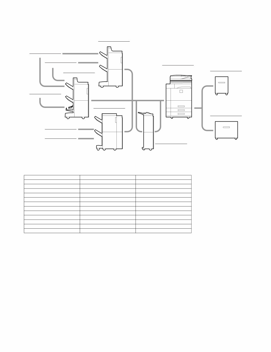
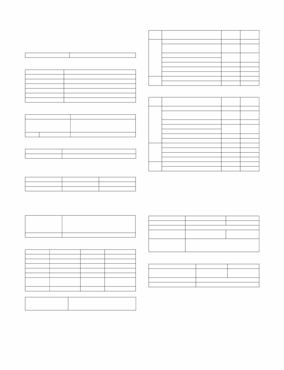
1. System configuration
2. Machine configuration
STD: Standard provision. OPT: Option
OPT*1: Product key target.
MX-M623N/M753N MX-M623U/M753U
Copier STD STD
PCL printer STD OPT*
1
PS printer OPT*
1
OPT*
1
Main body LCD COLOR WVGA 8.5" COLOR WVGA 8.5"
FAX OPT OPT
Scanner STD OPT*
1
Filing (Print hold function) STD STD
HDD STD STD
DSPF STD STD
Automatic duplex STD STD
Security OPT*
1
OPT*
1
Internet Fax OPT*
1
OPT*
1
MX-FN16
SADDLE STITCH FINISHER
SF-SC11
STAPLE CARTRIDGE
AR-SC3
STAPLE CARTRIDGE
AR-PN4A/B/C/D
PUNCH MODULE
MX-PN10A/B/C/D
PUNCH MODULE
MX-SC10
STAPLE CARTRIDGE
MX-FN15
FINISHER
MX-FN14
FINISHER
MX-CF10
INSERTER
MX-LC10
LARGE CAPACITY TRAY
MX-LCX3N
LARGE CAPACITY TRAY
MX-M623N/M753N
MX-M623U/M753U
DIGITAL MULTIFUNCTIONAL
SYSTEM

MX-M753N PRODUCT OUTLINE 1 – 2
3. Combination of options
STD: Standard provision. : Installable. *1: The printer expansion kit is required. *2: No support for some destinations.
*3: The SharpOSA Utility CD-ROM is not provided. *4: Standard for North America.
Section Name Model name
MX-M623N
MX-M753N
MX-M623U
MX-M753U
Product
key target
Remarks
Paper feed
system
LARGE CAPACITY TRAY MX-LC10
LARGE CAPACITY TRAY MX-LCX3N
Paper exit
system
INSERTER MX-CF10
FINISHER MX-FN15
SADDLE STITCH FINISHER MX-FN16
FINISHER MX-FN14 100 sheets staple
PUNCH MODULE AR-PN4A/B/C/D For finisher and saddle stitch
finisher
PUNCH MODULE MX-PN10A/B/C/D For 100 sheets staple finisher
STAPLE CARTRIDGE SF-SC11 For Finisher and
Saddle Finisher
STAPLE CARTRIDGE AR-SC3 For saddle
STAPLE CARTRIDGE MX-SC10 For 100 sheets staple finisher
Printer
expansion
PRINTER EXPANSION KIT MX-PB13 STD
PS3 EXPANSION KIT MX-PKX1
XPS EXPANSION KIT MX-PUX1 *
1
The expansion memory board
is required.
EXPANSION MEMORY BOARD MX-SMX3 1GB
Required when the XPS
expansion kit is used.
BARCODE FONT KIT AR-PF1
Image send
expansion
FACSIMILE EXPANSION KIT MX-FXX2 *
2
*
2
STAMP UNIT AR-SU1 *
2
*
2
STAMP CARTRIDGE AR-SV1 *
2
*
2
INTERNET FAX EXPANSION KIT MX-FWX1
NETWORK SCANNER EXPANSION KIT MX-NSX1 STD
ENHANCED COMPRESSION KIT MX-EBX3
Authentication/
Security
DATA SECURITY KIT MX-FR22U Commercial version
DATA SECURITY KIT MX-FR22 Authentication version
Application/
Solution
SHARPDESK 1 LICENSE KIT MX-USX1
SHARPDESK 5 LICENSE KIT MX-USX5
SHARPDESK 10 LICENSE KIT MX-US10
SHARPDESK 50 LICENSE KIT MX-US50
SHARPDESK 100 LICENSE KIT MX-USA0
APPLICATION INTEGRATION MODULE MX-AMX1
APPLICATION COMMUNICATION MODULE MX-AMX2 STD*
3
/
EXTERNAL ACCOUNT MODULE MX-AMX3 STD*
3
/
KEYBOARD MX-KBX2 STD/*
4
MX-M753N SPECIFICATIONS 2 – 1
MX-M753N
Service Manual [2] SPECIFICATIONS
1. Basic specifications
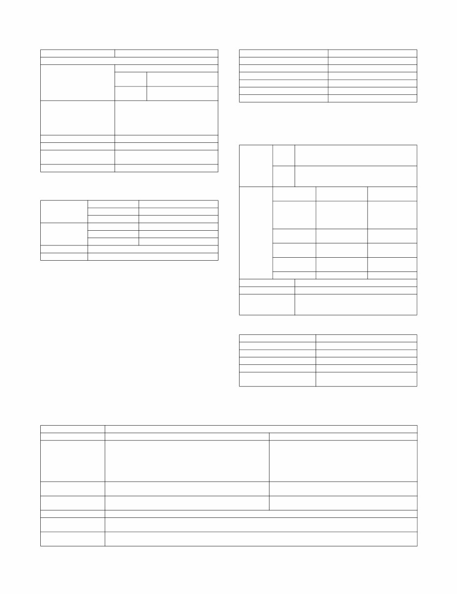
A. Base engine
(1) Type
(2) Engine composition
(3) Dimension / Weight
(4) Warm-up
* It may differ depending on the machine conditions.
(5) First copy time
* It may differ depending on the environment.
* Measuring conditions: A4 (8.5" x 11")
(6) Engine resolution
(7) Printable area
(8) Engine speed (ppm)
a. Tray (1-4, LCC)
b. Manual paper feed tray
*1: Switched by the service simulation setting. Postcard is set Low
before shipment.
*2: After completion of discharge of paper outside of the machine,
the next paper is fed. (The values are reference values.)
(9) Power source
NOTE: Check the shape of the power plug of the machine, and
insert it into a power outlet of the acceptable shape.
(10) Power consumption
*1: When the power supply is turned on, when the dehumidification
heater is OFF.
Type Desktop
Photo-conductor kind OPC (Drum diameter: 80mm)
Copying method Electronic photo (Laser)
Developing system Dry, 2-component magnetic brush development
Charging system Charged saw-tooth method
Transfer system Transfer belt
Cleaning system Counter blade
Fusing system Heat roller
Outer dimension (W x D x H) 728 x 683 x 1213mm
Machine dimension with the
bypass tray extended
(W x D).
1026 x 683mm
Weight Main unit Approx. 190kg
Warm-up time 30 seconds or less
Pre-heat Yes
Engine 62 CPM model 75 CPM model
Platen 4.0 second 3.5 second
DSPF 6.4 second 5.9 second
Resolution Writing
Copy: 600 x 600dpi
Print: 600 x 600dpi
1200 x 1200dpi
Gradation Equivalent to 256 gradation
A3 289 x 412mm 11" x "17 271 x 424mm
B4 242 x 356mm 8.5" x "14 208 x 348mm
A4 202 x 289mm 8.5" x "13.5 208 x 335mm
B5 174 x 249mm 8.5" x "13.4 208 x 332mm
A5 140 x 202mm 8.5" x "13 208 x 322mm
Postcard 92 x 140mm 8.5" x "11 208 x 271mm
8K 262 x 382mm Executive
(7.25" x "10.5)
183 x 259mm
16K 187 x 262mm 5.5" x "8.5 132 x 208mm
Void area Image loss Lead edge: 4mm or less
Rear edge: 4 mm or less
FR total: 8mm or less
Paper
type
Paper size
62 CPM
model
75 CPM
model
Plain
paper
A3, 11" x 17", 8K 34 39
B4, 8.5" x 14", 8.5" x 13", 8.5" x 13.4",
8.5" x 13.5"
39 45
A4R, 8.5" x 11"R, 16KR 45 48
B5R, 7.25" x 10.5"R
A5R, 5.5" x 8.5"R 45 48
A4, B5, 8.5" x 11", 16K 62 75
Extra 34 39
Heavy
paper
A4, B5, 8.5" x 11", 16K (Tray 3, 4) 43 43
Extra (Tray 4) 22 22
Paper
type
Paper size
62 CPM
model
75 CPM
model
Plain
paper
A3, 11" x 17", 8K 34 39
B4, 8.5" x 14", 8.5" x 13", 8.5" x 13.4",
8.5" x 13.5"
39 45
A4, 8.5" x 11", 16K, B5 62 75
B5R, 7.25" x 10.5"R 45 48
A4R, 16KR, 8.5" x 11"R
A5R, 5.5" x 8.5"R 45 48
Extra 34 39
Heavy
paper
A4, 8.5" x 11", 16K, B5 43 43
Extra 22 22
Postcard HIGH *
1
32 32
Postcard LOW *
2
21 21
OHP A4, 8.5" x 11" 43 43
A4R, 8.5" x 11"R 31 31
100V series 200V series
Voltage / Current 100 - 127V 16A USA:20A 220 - 240V 8A
Frequency 50/60Hz
Power source code Fixed type
(Direct connection)
Inlet
Power switch 2 switches
(Primary switch: in the front cover; Secondary
switch: the operation panel)
100V series 200V series
Max. Rated Power
Consumption *1
1.8kW 1.84kW
Moving time to Pre-heat mode 1 minutes (default)
Moving time to Sleep mode 1 minutes (default)
MX-M753N SPECIFICATIONS 2 – 2
B. Controller board
(1) Controller board
(2) Memory, hard disk
Memory capacity, HDD capacity
*1: The HDD capacity may vary depending on the production date.
C. Operation panel
(1) Display device
D. Scanner section
(1) Resolution/Gradation
(2) Document table
(3) Automatic document feeder
CPU Power QUICC III-MPC8533E (800MHz)
Interface
Ethernet 1 port
Interface 10Base-T, 100Base-TX,
1000Base-T
Support
Protocol
TCP/IP (IPv4, IPv6), IPX/
SPX, NetBEUI, EtherTalk
USB 2.0 (Host)
* Simultaneous connection
is inhibited. The total
current consumption must
not exceed 500mA.
The ports on the front and on the side of
the rear section cannot be used
simultaneously. (Exclusive use)
USB 2.0 (high speed) Device 1 port
Scanner expansion I/F Yes
Memory Refer to the section on “(2) Memory, hard
disk”.
Memory slot 2 slots (one is empty slot)
Copier memory
(Local Memory)
Standard Memory 512MB
Expansion Memory No
Max. 512MB
Printer memory
(System Memory)
Standard Memory 1GB
Expansion Memory 1GB
Max. 2GB
Codec memory 256MB
HDD *
4
80GB *
1
Size/resolution 8.5inch WVGA
Type Dot matrix LCD, touch panel
Display dot number 800 x 480 (WVGA)
Color Color
LCD drive display area (W x D) 184.8 x 110.88mm
LCD back-light Fluorescent lamp back-light system
LCD brightness adjustment Yes
Scanning
Resolution
(dpi)
Platen 600 x 600 dpi
600 x 400 dpi
600 x 300 dpi (Default)
DSPF 600 x 600 dpi
600 x 400 dpi
600 x 300 dpi (Default)
In sending
Resolution
(dpi)
Scanner
Internet Fax /
Direct SMTP
Fax
100dpi x 100dpi
200dpi x 100dpi
(halftone not
allowed)
Standard
(203.2 x 97.8 dpi)
(halftone not
allowed)
200dpi x 200dpi 200dpi x 200dpi
Fine
(203.2 x 195.6 dpi)
300dpi x 300dpi 200dpi x 400dpi
Super Fine
(203.2 x 391 dpi)
400dpi x 400dpi 400dpi x 400dpi
Ultra Fine
(406.4 x 391 dpi)
600dpi x 600dpi 600dpi x 600dpi ---
Exposure lamp Xenon
Reading gradation 10bits
Output gradation B/W: 1bit
Grayscale: 8bit
Full color: RGB colors are 8bit each
Type Document table fixed system (Flat bed)
Scanning area 297 x 432mm
Original standard position Left bottom reference
Detection Yes
Detection size Automatic detection
Dehumidifying heater
(Scanner section)
Supplied as a service part
Type DSPF (Duplex single pass feeder)
Scan speed Monochrome (A4 / 8.5" x 11") Color (A4 / 8.5" x 11") only
Copy Single: 75-sheet/min. (600 x 300 dpi)
53-sheet/min. (600 x 400 dpi)
41-sheet/min. (600 x 600 dpi)
Duplex: 75-page/min. (600 x 300 dpi)
53-page/min. (600 x 400 dpi)
41-page/min. (600 x 600 dpi)
N/A
Fax / Internet Fax Single: 75-sheet/min. (200 x 200 dpi)
Duplex: 75-page/min. (200 x 200 dpi)
N/A
Scanner Single: 75-sheet/min. (200 x 200 dpi)
Duplex: 75-page/min. (200 x 200 dpi)
Single: 75-sheet/min. (200 x 200 dpi, 8 bit)
Duplex: 75-page/min. (200 x 200 dpi, 8 bit)
Original setup direction Upward standard (1 to N feeding standard)
Original standard
position
Center standard (Rear one-side standard for random feeding)
Face Up (1 to N Feeding standard)
Original transport
method
Sheet-through method
MX-M753N SPECIFICATIONS 2 – 3
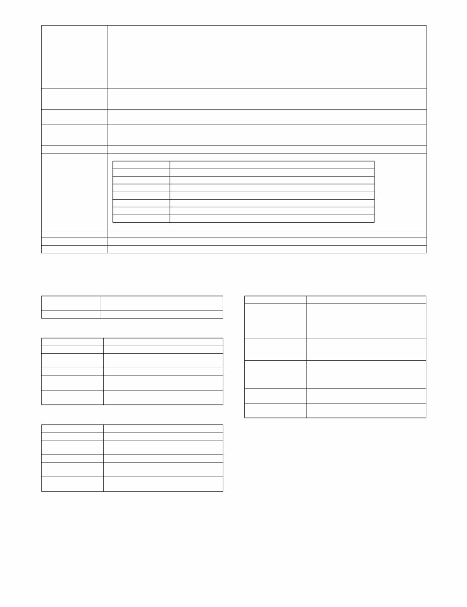
E. Paper feed section
(1) Type
(2) Tray 1 (Main unit: LCC left tray)
(3) Tray 2 (Main unit: LCC right tray)
(4) Tray 3 (Main unit: multi-purpose tray)
*1: 8.5" x 11", A4, B5 only
*2: 8.5" x 11", A4 only
Original size Standard size: (Refer to the "paper detection size")
Long paper: 1000 mm (Monochrome binary only)
Internet Fax 600 x 600 dpi: Max. 800 mm. When scan 400 dpi or more, long paper is not available.
Mix paper feed (Same series, same width paper) enabled
Random paper feed combination
Mix feeding available. (same system, same width)
Random feeding (feeding of different types / different widths)
Only the following combinations of 2 size types are allowed:
either A3 or A4 and either B4 or B5; either B4 or B5 and either A4R or A5 and 11-inch and 8.5-inch. AMS available.
Original copy weight Single: (Thin paper) 9 - 13 lb bond (35 - 49 g/m
2
), (plain paper) 13 - 34 lb bond (50 - 128 g/m
2
)
* Thin paper mode (36 pages/minute (A4, 8.5" x 11", 600dpi)) is set up for the thin paper.
Duplex: 13 - 28 lb bond (50 - 34 g/m
2
)
Max. loading capacity of
documents
Max. 150 sheets (21lbs Bond, 80g/m
2
), or Max. height: 1/2 inch, 19.5mm or less
Un-acceptable originals
for feeding.
OHP, second original paper, tracing paper, carbon paper, thermal paper, paper with wrinkles, folds, or breakage, pasted paper, cutout
document, document printed with ink ribbon, documents with perforation other than 2- or 3-holes (Perforated document by punch unit
is allowed.)
Detection Yes
Paper detection size
(DSPF)
Auto detection (Switching one type of detection unit)
Inch-1 11" x 17", 8.5" x 14", 8.5" x 11", 8.5" x 11"R, 5.5" x 8.5", A3, A4
Inch-2 11" x 17", 8.5" x 13", 8.5" x 11", 8.5" x 11"R, 5.5" x 8.5", A3, A4
Inch-3 11" x 17", 8.5" x 13.4", 8.5" x 11", 8.5" x 11"R, 5.5" x 8.5", A3, A4
AB-1 A3, B4, A4, A4R, B5, B5R, A5, 11" x 17", 8.5" x 14", 8.5" x 11"
AB-2 A3, B4, A4, A4R, B5, B5R, A5, 11" x 17", 8.5" x 13", 8.5" x 11"
AB-3 8K, 16K, 16KR, A3, B4, A4, A4R, A5, 11" x 17", 8.5" x 13", 8.5" x 11"
AB-4 A3, B4, A4, A4R, B5, B5R, A5, 11" x 17", 8.5" x 13.4", 8.5" x 11"
AB-5 A3, B4, A4, A4R, B5, B5R, A5, 11" x 17", 8.5" x 13.5", 8.5" x 11"
* 5.5" x 8.5"R, A5R cannot be detected.
Paper feeding direction Right hand feeding
Finish stamp Option
Power source Provided from main unit
Type 4-stage paper feed tray
(Parallel LCC + 2 tray + Multi manual paper feed)
Dehumidifying heater Service parts (Supported by kit)
Paper capacity Plain paper: 800 sheets (80 g/m
2
)
Paper size 8.5" x 11", A4
Paper type Plain paper, printed paper, recycled paper,
letter head, punched paper, colored paper
Feedable paper weight Plain paper: 16 - 28 lb bond (60 - 105g/m
2
)
Paper size setting
when shipping
AB series: A4
Inch series: 8.5" x 11"
Paper remaining
detection
Yes (Paper empty and 3 levels)
Paper capacity Plain paper: 1200 sheets (80 g/m
2
)
Paper size A4, 8.5" x 11", B5 (Setting by parts)
Paper type Plain paper, printed paper, recycled paper,
letter head, punched paper, colored paper
Feedable paper weight Plain paper: 16 - 28 lb bond (60 - 105g/m
2
)
Paper size setting
when shipping
AB series; A4
Inch series; 8.5" x 11"
Paper remaining
detection
Yes (Paper empty and 3 levels)
Paper capacity Plain paper: 500 sheets (80 g/m
2
)
Paper size A3, B4, A4, A4R, B5, B5R, A5R
11" x 17", 8.5" x 14" (216 x 356),
8.5" x 13.5 (216 x 343), 8.5" x 13.4" (216 x 340),
8.5" x 13" (216 x 330), 8.5" x 11", 8.5" x 11"R,
7.25" x 10.5"R, 5.5" x 8.5"R, 8K, 16K, 16KR
Paper type Plain paper, printed paper, recycled paper,
letter head, punched paper, colored paper,
heavy paper*
1
, OHP, label sheet*
1
, tab paper*
2
Feedable paper weight Plain paper:
16 - 28 lb bond (60 - 105g/m
2
)
Heavy paper:
28 lb bond - 110 lb index (106 - 209g/m
2
)
Paper size setting
when shipping
AB series: A3
Inch series: 11" x 17"
Paper remaining
detection
Yes (Paper empty and 3 levels)
You're Reading a Preview
What's Included?
Fast Download Speeds
Online & Offline Access
Access PDF Contents & Bookmarks
Full Search Facility
Print one or all pages of your manual
$33.99
Viewed 84 Times Today


Secure transaction
What's Included?
Fast Download Speeds
Online & Offline Access
Access PDF Contents & Bookmarks
Full Search Facility
Print one or all pages of your manual
$33.99
This manual for the Sharp MX-M623N, MX-M623U, MX-M753N, MX-M753U copier is available in PDF format. It contains detailed diagrams, pictures, and comprehensive procedures for diagnosing and repairing the copier. Whether you are a professional mechanic or a DIY enthusiast, this manual provides valuable information.
You can easily print, zoom, or read any diagram, picture, or page from this Service Manual. Each chapter is fully detailed and includes simulation codes, trouble codes, maintenance procedures, reset procedures, and diagnostic procedures for the Sharp MX-M623N, MX-M623U, MX-M753N, MX-M753U photocopier.
The manual includes the following sections:
- NOTE FOR SERVICING
- Precautions for servicing
- Warning for servicing
- Note for installation site
- Note for handling PWB and electronic parts
- Note for repairing/replacing the LSU
- Note for handling the drum unit, the transfer unit, the developing unit, and the fusing unit
- Screw tightening torque
- PRODUCT OUTLINE
- System configuration
- Machine configuration
- Combination of options
- SPECIFICATIONS
- Basic specifications
- Functional specifications
- CONSUMABLE PARTS
- Supply system table
- Maintenance parts list
- Definition of Developer and Drum life end
- Production number identification
- EXTERNAL VIEW AND INTERNAL STRUCTURE
- Identification of each section and functions
- ADJUSTMENTS AND SETTINGS
- General
- Adjustment item list
- Details of adjustment
- SIMULATION
- General (Including basic operations)
- List of simulation codes
- Details of simulation
- SELF DIAG AND TROUBLE CODE
- Self diag
- Trouble code list
- Details of trouble code
- Paper JAM code
- Necessary works when replacing the PWB and the HDD
- OPERATIONAL DESCRIPTIONS
- Operation panel
- Scanner section
- Manual paper feed section
- Tray paper feed section
- Paper transport section, Duplex section
- LSU section
- Photo-conductor section
- Toner supply section
- Developing section
- Transfer section
- Fusing section
- Paper exit section
- Automatic document feeder
- MAINTENANCE
- Necessary execution items (Before and after maintenance)
- Contents of the maintenance codes and countermeasures (Relationship between various counter values and display messages)
- Maintenance system table
- DISASSEMBLY AND ASSEMBLY
- Exterior
- Operation panel section
- Scanner section
- Manual paper feed section
- Tray paper feed section
- Paper transport and duplex section
- LSU section
- Photo-conductor section
- Toner supply section
- Developing section
- Transfer section
- Fusing section
- Paper exit section
- Drive section
- PWB section
- Fan section
- Filter section
- Automatic document feeder
- Other
- FIRMWARE UPDATE
- Outline
- Update procedure
- ELECTRICAL SECTION
- Block diagram
- Actual wiring chart
- Signal list
- SERVICE WEB PAGE
- General
- Details and operation procedures
Number of pages: 428


