


(1/13)
MP240 / MP245
MP260 / MP268
MP480 / MP486
SIMPLIFIED SERVICE MANUAL
QY8-13BV-000
Rev. 00: June 2008
Canon Inc.

(2/13)
TABLE OF CONTENTS
1. LIST OF ERROR DISPLAY / TROUBLESHOOTING
1-1. Operator Call Errors (Alarm LED Lit In Orange)
1-2. Service Call Error (Cyclic Blinking in Orange (Alarm LED) and Green (ON LED)
2. ADJUSTMENT / SETTINGS
2-1. Service Mode
2-2. User Mode
2-3. Special Notes on Assembling
2-4. Grease Application
2-5. Notes on Transportation

(3/13)
1. LIST OF ERROR DISPLAY / TROUBLESHOOTING
1-1. Operator Call Errors (Alarm LED Lit In Orange)
Errors and warnings are displayed by the following ways:
- Operator call errors are indicated by the Alarm LED lit in orange, and the error and its solution
are displayed on the LCD.
- Messages during printing from a computer are displayed on the MP driver Status Monitor.
- Error codes are printed in the "operator call/service call error record" area in EEPROM
information print.
Buttons valid when an operator call error occurs:
- ON button: To turn the machine off and on again.
- OK button: To clear and recover from an error. In some operator call errors, the error will
automatically be cleared when the cause of the error is eliminated, and pressing
the OK button may not be necessary.
- Stop or Stop/Reset button: To cancel the job at error occurrence, and to clear the error.
Error
Error
code
*1 U No.
*2
Message on the LCD
*2
Solution
No paper in the rear
tray.
[1000] E02 --- There is no paper.
Load paper and press
[OK].
Set the paper in the rear tray, and press
the OK button.
Paper jam. [1300] E03 --- The paper is jammed.
Clear the paper and
press [OK].
Remove the jammed paper, and press
the OK button.
Ink cartridge not
installed, or not
properly installed.
[1401] E05 U051 Print head is not
installed. Install the print
head.
U051
Install the ink cartridge properly. If the
error is not cleared, the ink cartridge
may be defective. Replace the ink
cartridge.
Ink cartridge
temperature sensor
error.
[1403] E05 U052 The type of print head is
incorrect. Install the
correct print head.
U052
Re-set the ink cartridge. If the error is
not cleared, the ink cartridge may be
defective. Replace the ink cartridge.
Non-supported ink
cartridge is installed.
[1485] E05 U059 The ink cartridge cannot
be recognized.
U059
A non-supported ink cartridge is
installed. Install the supported ink
cartridge. If the error is not cleared, the
ink cartridge may be defective. Replace
the ink cartridge.
Ink cartridge in a
wrong position.
[1486] E07 U076 Some ink cartridges are
not installed in place.
U076
Install the ink cartridge in the correct
position. If the error is not cleared, the
ink cartridge may be defective. Replace
the ink cartridge.
Multiple ink cartridges
of the same color
installed.
[1487] E07 U075 Some ink cartridges are
not installed in place.
U075
Confirm that each ink cartridge is
installed in the correct position. If the
error is not cleared, the ink cartridge
may be defective. Replace the ink
cartridge.
Ink cartridge hardware
error
[1682] E15 U150 The ink cartridge cannot
be recognized.
U150
Re-set the ink cartridge. If the error is
not cleared, the ink cartridge may be
defective. Replace the ink cartridge.
Ink cartridge not
recognized.
[1684] E14 U140 The ink cartridge cannot
be recognized.
U140
A non-supported ink cartridge is
installed. Install the supported ink
cartridge.

(4/13)
Error
Error
code
*1 U No.
*2
Message on the LCD
*2
Solution
The remaining ink
amount unknown.
[1686] E13 U162 Ink may have run out.
Replacing the ink
cartridge is
recommended.
U162
Replace the ink cartridge. Printing with
an empty ink tank can damage the
machine.
To continue printing without replacing
the ink cartridge, press the Stop or
Stop/Reset button for 5 sec. or longer to
disable the function to detect the
remaining ink amount. (After the
operation, it is recorded in the machine
EEPROM that the function to detect the
remaining ink amount was disabled.)
Ink cartridge not
completely installed.
[1687] E04 U053 The ink cartridge cannot
be recognized.
U053
Re-set the ink cartridge. If the error is
not cleared, the ink cartridge may be
defective. Replace the ink cartridge.
No ink. [1688] E16 U163 Ink has run out. Replace
the ink cartridge.
U163
Replace the ink cartridge. Printing with
an empty ink tank can damage the
machine.
To continue printing without replacing
the ink cartridge, press the Stop or
Stop/Reset button for 5 sec. or longer to
disable the function to detect the
remaining ink amount. (After the
operation, it is recorded in the machine
EEPROM that the function to detect the
remaining ink amount was disabled.)
Warning: The ink
absorber becomes
almost full.
[1700] E08 --- The ink absorber is
almost full. Press [OK] to
continue printing.
Replace the ink absorber, and reset the
ink absorber counter. (See 2-1, "Service
Mode.")
Pressing the Stop or Stop/Reset button
will exit the error, and enable printing
without replacing the ink absorber.
However, when the ink absorber
becomes full, no further printing can be
performed unless the applicable ink
absorber is replaced.
The connected digital
camera or digital video
camera does not
support Camera Direct
Printing.
[2001] E09 --- Incompatible device
detected. Remove the
device.
Remove the cable between the camera
and the machine.
Non-supported hub [2002] E19 --- An unsupported USB
hub is connected.
Remove the hub.
Remove the applicable USB hub from
the PictBridge (USB) port.
*1: MP240 / MP245 and MP260 / MP268 only.
*2: MP480 / MP486 only.

(5/13)
1-2. Service Call Error (Cyclic Blinking in Orange (Alarm LED) and Green (ON LED)
Cycles of
blinking in
orange
and green
Error
Error
code
*1
Conditions
Solution
(Replacement of listed parts, which are likely
to be faulty)
2 times Carriage error [5100]
P02
An error occurred in the
carriage encoder signal.
1) Confirm that no foreign material is in the area
where the carriage moves.
2) Clean the timing slit film.
3) Replace the following items:
- Timing slit film
- Carriage unit
- Logic board
- Carriage motor
3 times Line feed error [6000]
P03
An error occurred in the
LF encoder signal.
Replace the following items:
- Timing slit disk film
- Logic board
5 times ASF cam sensor
error
[5700]
P05
This error takes place
when feeding paper
from the rear tray after
an error occurred in the
rear tray cam sensor.
Replace the following items:
- ASF/PE sensor unit
- Drive unit
- Logic board
6 times Internal
temperature error
[5400]
P06
The internal
temperature is not
normal.
Replace the following item:
- Logic board
7 times Ink absorber full Japan:
[5B00]
Others:
[5B01]
P07
The ink absorber
becomes full.
Replace the ink absorber (ink absorber kit), and
reset the ink absorber counter.
8 times Print head
temperature rise
error
[5200]
P08
The print head
temperature exceeded
the specified value.
Replace the following items:
- Ink cartridge
- Logic board
9 times EEPROM error [6800]
[6801]
P09
A problem occurred in
reading from or writing
to the EEPROM.
Replace the following item:
- Logic board
10 times VH monitor error [B200]
P10
The print head voltage
is abnormal.
Replace the following items:
- Ink cartridge
- Logic board
15 times USB VBUS
overcurrent
[9000]
P15
The USB VBUS is
overloaded.
Replace the following item:
- Logic board
20 times Other hardware
error
[9000]
P20
---
Replace the following item:
- Logic board
22 times Scanner error [5011]
P22
The scanner unit is
faulty.
Replace the following items:
- Scanner unit
- Logic board
Power LED
turned off
Alarm LED
lit
ROM error
RAM error
None The check sum value is
incorrect in the flash
ROM or RAM check at
hard-power-on.
Replace the following item:
- Logic board
*1: MP240 / MP245 and MP260 / MP268 only.
(6/13)
2. ADJUSTMENT / SETTINGS
2-1. Service Mode
< Service mode operation procedures >
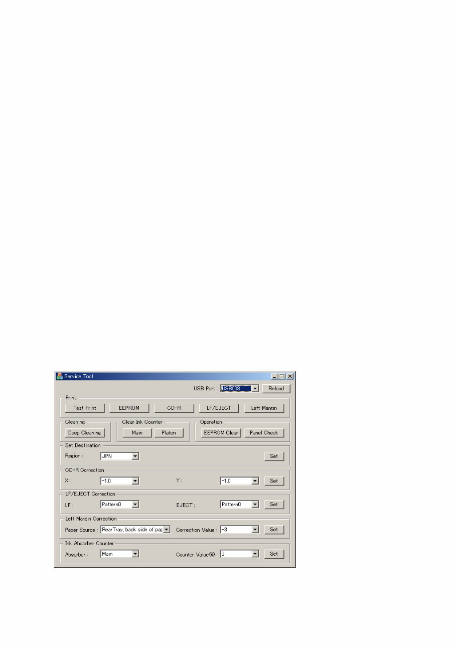
Use the Service Tool on the connected computer.
1) Start the machine in the service mode.
i. With the machine power turned off, while pressing the Stop or Stop/Reset button, press
and hold the ON button. (DO NOT release the buttons).
ii. When the Power LED lights in green, while holding the ON button, release the Stop or
Stop/Reset button. (DO NOT release the ON button.)
iii. While holding the ON button, press the Stop or Stop/Reset button 2 times, and then release
both the ON and Stop or Stop/Reset buttons. (Each time the Stop or Stop/Reset button is
pressed, the Alarm and Power LEDs light alternately, Alarm in orange and Power in green,
starting with Alarm LED.)
iv. When the Power LED lights in green and the machine displays as follows, the machine is
ready for the service mode operation:
- MP480 / MP486: "Service Mode Idle" on the LCD
- MP260 / MP268: "0" (zero) on the 7-segment LED
- MP240 / MP245: "0" (zero) on the 7-segment LED
2) Start the Service Tool on the connected computer, and click the button for a desired function.
- During operation of the selected function, all the buttons of the Service Tool are dimmed and
inactive.
- When the operation is completed, "A function was finished." is displayed, and another function
can be selected.
- If a non-supported function is selected, "Error!" is displayed. Click OK in the error message
dialog box to exit the error.
< Service Tool Functions >
(1) (2) (3) (4) (5)
(6) (7) (8) (9) (10)
(11)
(12)
(13)
(14)
(15)

(7/13)
No. Name Function Remarks
(1) Test Print Service test print Service test print items:
- Model name
- ROM version
- Ink absorber counter value (ink amount in the
ink absorber)
- USB serial number
- Destination
- EEPROM information
- Barcode (model name + destination), etc.
(2) EEPROM EEPROM information print The dialog box opens to select the paper source.
Select the rear tray, and click OK.
EEPROM information print items:
- Model name
- Destination
- ROM version
- Ink absorber counter value (ink amount in the
ink absorber)
- Print information
- Error information, etc.
(3) CD-R CD-R check pattern print Not used.
(4) LF/Eject LF/Eject correction pattern
print
Not used.
(5) Left Margin Left margin pattern print Not used.
(6) Deep Cleaning Print head deep cleaning Cleaning of Black and Color at the same time
(7) Main Main ink absorber counter
reset
Set a sheet of A4 or Letter sized paper. After the
ink absorber counter is reset, the counter value is
printed automatically.
(8) Platen Platen ink absorber
counter reset
Not used.
(9) EEPROM Clear EEPROM initialization The following items are NOT initialized, and the
shipment arrival flag is not on:
- Destination settings
- Absorbed ink amount
- USB serial number
- Region code of ink cartridge
- Record of ink absorber counter resetting and
setting
- Record of repair at the production site
(10) Panel Check Button and LCD test See "Button and LCD test" below.
(11) Set Destination Destination settings Select the destination, and click Set.
ASA, AUS, BRA, CHN, CND, EUR, JPN, KOR,
LTN, TWN, USA
(12) CD-R Correction CD / DVD print position
correction
Not used.
(8/13)
No. Name Function Remarks
(13) LF/EJECT Correction LF/Eject correction value
setting
Not used.
(14) Left Margin Correction Left margin correction
value setting
Not used.
(15) Ink Absorber Counter Ink absorber counter value
setting
See "Ink absorber counter setting" below.
< Button and LCD test >
Confirm the operation after replacement of the operation panel unit, LCD unit, or logic board.
To perform the test, start the machine in the service mode, then click Panel Check of the Service
Tool on the connected computer.
MP240 / MP245, MP260 / MP268:
1) In the Button and LCD test mode, press each button of the machine.
"1" is displayed on the 7-segment LED at the beginning, and it is incremented by one each time
the button is pressed. When all the buttons are pressed, "E" is displayed.
2) Press the ON button to exit the Button and LCD test and return to the menu selection.
MP480 / MP486:
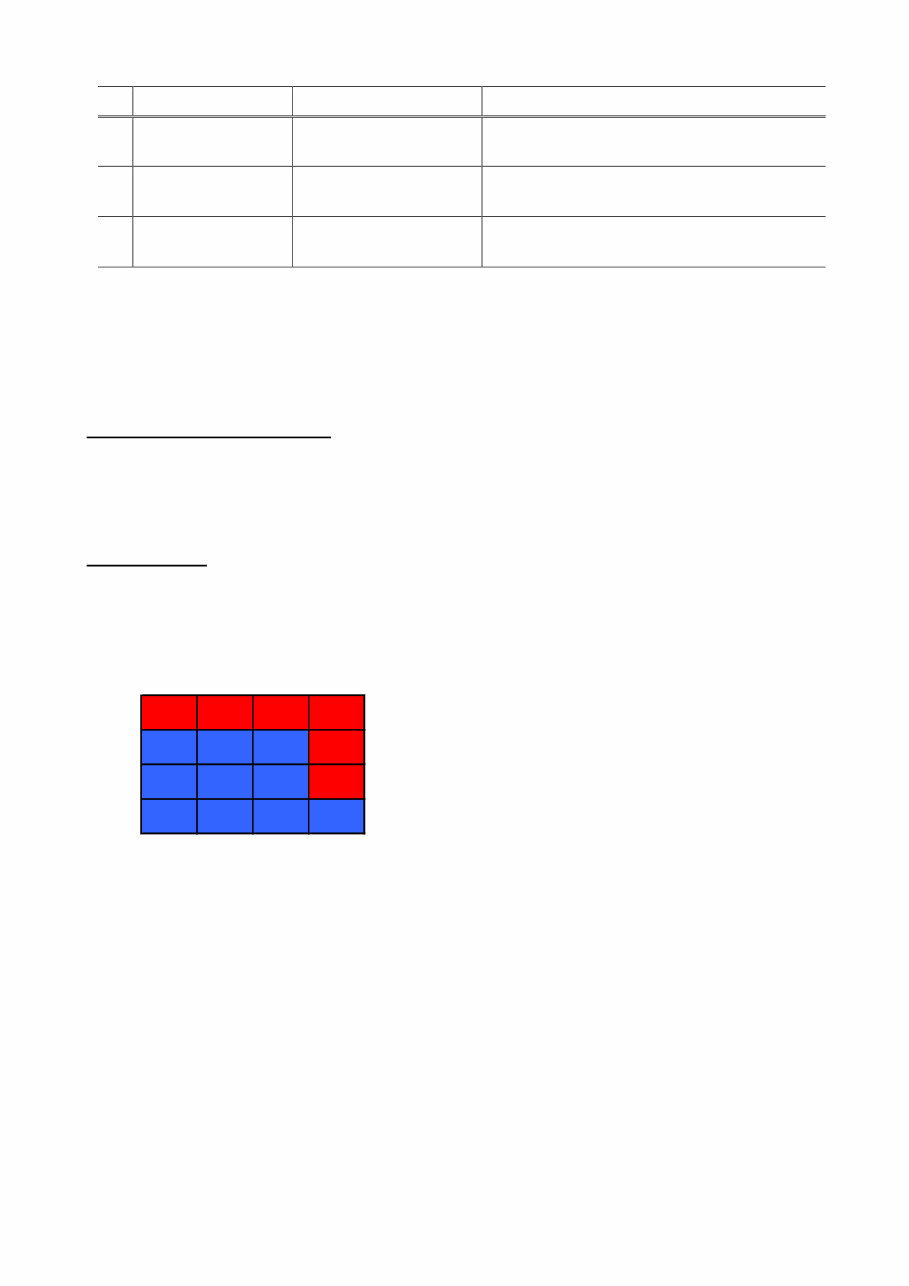
1) In the Button and LCD test mode, the LCD turns blue, waiting for a button to be pressed.
2) Press each button of the operation panel.
The LCD is divided into segments, representing each button. The color of a segment
corresponding to the pressed button changes to red.
After all the 11 buttons are pressed, the remaining segments turn red at the same time.
1 2 3 4
12 13 14 5
11 16 15 6
10 9 8 7
1: ON button 7: Right cursor button
2: Back button 8: Black button
3: OK button 9: Color button
4: Up cursor button 10: Stop button
5: Down cursor button 11: Menu button
6: Left cursor button

(9/13)
3) Open the scanning unit (cover). The color pattern is displayed on the LCD.
Red Black White Cyan
Green White Black Magenta
Blue Black White Yellow
4) Press the ON button to exit the Button and LCD test and return to the menu selection.
< Ink absorber counter setting >
Set the ink absorber counter value to a new EEPROM after the logic board is replaced in servicing.
1) Start the machine in the service mode.
2) In the Ink Absorber Counter section of the Service Tool, select an appropriate ink absorber
type from the Absorber pull-down menu.
For the MP480 / MP486, select Main.
3) From the Counter Value (%) pull-down menu, select the value which is the closest to the actual
counter value confirmed before replacement of the logic board.
4) Click Set.
2-2. User Mode
Function Procedures Remarks
Nozzle check pattern
printing
Perform via the machine operation
panel, or from the MP driver
Maintenance tab.
Set a sheet of plain paper (A4 or Letter) in
the rear tray.
Print head cleaning Perform via the machine operation
panel, or from the MP driver
Maintenance tab.
Unclogging of the print head nozzles, and
maintenance to keep the print head
conditions good.
If there is a missing portion or white streaks
in the nozzle check pattern printout, perform
this cleaning.
Print head deep
cleaning
Perform via the machine operation
panel, or from the MP driver
Maintenance tab.
If print head manual cleaning is not effective,
perform this cleaning. Since the deep
cleaning consumes more ink than regular
cleaning, it is recommended to perform deep
cleaning only when necessary.
Manual print head
alignment
Perform from the MP driver
Maintenance tab.
For the MP480 / MP486, the
alignment can also be performed
via the machine operation panel.
Set a sheet of plain paper (A4 or Letter) in
the rear tray.
Partially automatic print
head alignment
Only for the MP240 / 245 and
MP260 / MP268.
Perform via the machine operation
panel.
Set a sheet of plain paper (A4 or Letter) in
the rear tray.
(10/13)
Function Procedures Remarks
Print head alignment
value printing
Perform from the MP driver
Maintenance tab.
For the MP480 / MP486, the
alignment can also be performed
via the machine operation panel.
Confirmation of the current print head
alignment values.
Paper feed roller
cleaning
Perform via the machine operation
panel, or from the MP driver
Maintenance tab.
The paper feed rollers rotate while being
pushed to the paper lifting plate. Since the
rollers will wear in this cleaning, it is
recommended to perform this only when
necessary.
Bottom plate cleaning Perform via the machine operation
panel, or from the MP driver
Maintenance tab.
Cleaning of the platen ribs when the back
side of paper gets smeared.
Fold a sheet of plain paper (A4 or Letter) in
half crosswise, then unfold and set it in the
rear tray with the folded ridge facing down.
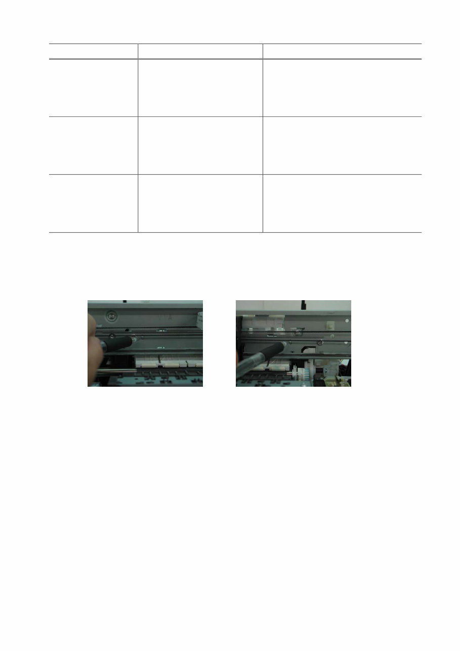
2-3. Special Notes on Assembling
(1) Carriage rail and main chassis adjustment
< Carriage rail >
Perform the following adjustments when attaching the carriage rail:
1) Before loosening the screws, mark the their positions on the rail.
2) In attaching the carriage rail, make sure that the screws fit to the marks made in step 1)
respectively, then fasten the screws.
3) Be sure to perform the confirmation test detailed below; confirm that the print quality is
proper and the print head is not contacting the paper.
< Main chassis >
After the main chassis is attached, be sure to perform the confirmation test detailed below;
confirm that the print quality is proper and the print head is not contacting the paper.
< Confirmation test >
Using Photo Paper Pro, and with the paper thickness lever set to the left position (normal
position), print an image and confirm that the print quality is proper, and the print head is free
from contacting the paper.
If the print quality is not proper, or the print head contacts the paper, adjust the head-to-paper
distance in the following procedures:
< How to adjust the head-to-paper distance >
1) Mark the current position of the screws at the both ends of the chassis. (See the step 1) of
the carriage rail adjustment above.)
You're Reading a Preview
What's Included?
 Lifetime Access
Fast Download Speeds
Online & Offline Access
Access PDF Contents & Bookmarks
Full Search Facility
Print one or all pages of your manual
$31.99
Canon Pixma MP240 MP260 MP480 Simplified Service Manual & Repair Guide
Viewed 21 Times Today

What's Included?
Lifetime Access
Fast Download Speeds
Online & Offline Access
Access PDF Contents & Bookmarks
Full Search Facility
Print one or all pages of your manual
$31.99

Secure transaction
What's Included?
Lifetime Access
Fast Download Speeds
Online & Offline Access
Access PDF Contents & Bookmarks
Full Search Facility
Print one or all pages of your manual
Description
If your Canon Pixma printer is in need of repair or maintenance, you can save money by doing it yourself. This service and repair manual covers the following models:
- Canon Pixma MP240
- Canon Pixma MP260
- Canon Pixma MP480
The manual includes the following contents:
- List of error display
- Operator call errors (LED lit in orange)
- Service call error (lit in orange and green)
- Troubleshooting
- Adjustments
- Exploded view
- Parts list catalog
This service and repair manual contains illustrated pictures and step-by-step instructions used in service shops. It consists of 20 pages and is available in English language. It is compatible with Windows and Mac operating systems. The manual is printable, and we offer instant delivery.
If you cannot find a specific manual, please email us, and we will assist you promptly. Buy from us with the assurance of becoming a satisfied customer. Thank you.


