


High-Definition LCD TV Service Manual
Models: LT3200, LT3700, LT4200, LT4700
Downloaded from www.Manualslib.com manuals search engine

Copyright 2007, 2008 Hewlett-Packard Development Company, L.P. The information contained herein is
subject to change without notice.
Microsoft and Windows are trademarks of Microsoft Corporation in the U.S. and other countries.
The only warranties for HP products and services are set forth in the express warranty statements accompanying
such products and services. Nothing herein should be construed as constituting an additional warranty HP shall
not be liable for technical or editorial errors or omissions contained herein.
This document contains proprietary information that is protected by copyright. No part of this document may be
photocopied, reproduced, or translated to another language without the prior written consent of Hewlett-Packard
Company.
Service Reference Guide
Business PCs
Second Edition (April 2008)
First Edition (June 2007)
Document Part Number: 454404-002
Downloaded from www.Manualslib.com manuals search engine

HP High-Definition LCD TV Service Manual iii
Table of Contents
High-Definition LCD TV Service Manual ................................................................................................................ 1
Models: LT3200, LT3700, LT4200, LT4700 ................................................................................................................. 1
Table of Contents........................................................................................................................................................ iii
Important Service Safety Precautions ....................................................................................................................... 1
Warnings and Cautions ................................................................................................................................................. 1
Safe Handling and Servicing......................................................................................................................................... 2
Repair Tips ............................................................................................................................................................... 3
About Lead-Free Solder ........................................................................................................................................... 3
Suggested Pb-Free Solder ........................................................................................................................................ 4
Servicing of Surface-Mounted Devices (SMDs) ...................................................................................................... 4
Rework on Ball Grid Array (BGA) ICs.................................................................................................................... 5
Product Information and Specifications ................................................................................................................... 6
Product Information ...................................................................................................................................................... 6
Product Profile ......................................................................................................................................................... 6
Specifications ................................................................................................................................................................ 6
LCD Panel Module................................................................................................................................................... 6
General TV Specifications LT3200 and LT3700 ..................................................................................................... 7
General TV Specifications LT4200 and LT4700 ..................................................................................................... 9
I/O Connectors ........................................................................................................................................................11
Factory Preset Display Modes.................................................................................................................................11
Controlling the Onscreen Display .......................................................................................................................... 12
TV Indicators and Controls .................................................................................................................................... 12
Remote Control ...................................................................................................................................................... 13
TV Connectors ....................................................................................................................................................... 14
Connectors.............................................................................................................................................................. 17
Basic Operation ......................................................................................................................................................... 20
Basic Operation........................................................................................................................................................... 20
OSD (On-Screen Display) Functions – Simplemenu ............................................................................................ 20
OSD Functions – Fullmenu ................................................................................................................................... 21
Command Table RS-232 ............................................................................................................................................. 25
Return messages.......................................................................................................................................................... 32
Special command extension ................................................................................................................................... 32
Replaceable Parts ...................................................................................................................................................... 33
Parts List by Model ..................................................................................................................................................... 33
Model LT3200 ........................................................................................................................................................ 33
Model LT3700 ....................................................................................................................................................... 34
Model LT4200 ....................................................................................................................................................... 35
Model LT4700 ....................................................................................................................................................... 36
Replacement Parts List Reference Pictures ............................................................................................................ 37
Removal and Replacement ....................................................................................................................................... 42
Equipment and Tools Needed for Removal and Replacement .................................................................................... 42
Downloaded from www.Manualslib.com manuals search engine

iv HP High-Definition LCD TV Service Manual
Tools ....................................................................................................................................................................... 42
After Service Checklist .......................................................................................................................................... 42
Basic Adjustment Settings ...................................................................................................................................... 42
Four Models – Comparison Pictures ........................................................................................................................... 43
LT3200 ................................................................................................................................................................... 43
LT3700 ................................................................................................................................................................... 43
LT4200 ................................................................................................................................................................... 44
LT4700 ................................................................................................................................................................... 44
Removal Procedures ................................................................................................................................................... 45
Removal Order ....................................................................................................................................................... 45
Screws .................................................................................................................................................................... 45
Removing the Pedestal ........................................................................................................................................... 46
Disassembling the Pedestal .................................................................................................................................... 47
Removing the Back Cover ..................................................................................................................................... 48
Removing the Function Keyboard.......................................................................................................................... 49
Removing the Infrared Board ................................................................................................................................. 50
Removing the Wall Mount Brackets ...................................................................................................................... 51
Removing the Board Cover .................................................................................................................................... 52
Removing the Main Board ..................................................................................................................................... 52
Removing the Power Supply .................................................................................................................................. 56
Removing the Main Bracket................................................................................................................................... 60
Removing the Inverters .......................................................................................................................................... 61
Removing the Speakers .......................................................................................................................................... 64
Removing the Control Board ................................................................................................................................. 66
Removing the Front Bezel...................................................................................................................................... 70
Diagnostics ................................................................................................................................................................. 71
LED Indicators ....................................................................................................................................................... 71
Software version information...................................................................................................................................... 71
How to run diagnostics ............................................................................................................................................... 71
How to get back to normal TV operation after running diagnostics ........................................................................... 72
Installation menu......................................................................................................................................................... 72
Hotel mode .................................................................................................................................................................. 73
How to enable and disable...................................................................................................................................... 74
Troubleshooting ......................................................................................................................................................... 75
Remote Control ........................................................................................................................................................... 75
Function Key............................................................................................................................................................... 76
Power: TV Does Not Turn On..................................................................................................................................... 77
Audio .......................................................................................................................................................................... 78
VGA Input................................................................................................................................................................... 79
HDMI Input ................................................................................................................................................................ 80
DVI Input .................................................................................................................................................................... 81
YPbPr Input ................................................................................................................................................................ 82
TV/Video/S-video Input .............................................................................................................................................. 83
Troubleshooting Tips .................................................................................................................................................. 84
No Power................................................................................................................................................................ 84
No Video ................................................................................................................................................................ 84
Downloaded from www.Manualslib.com manuals search engine

HP High-Definition LCD TV Service Manual v
Keypad abnormal ................................................................................................................................................... 84
LED Display abnormal........................................................................................................................................... 84
Abnormal Display .................................................................................................................................................. 84
LED Display abnormal........................................................................................................................................... 85
LCD Panel Troubleshooting Tips ................................................................................................................................ 85
Inverter board ......................................................................................................................................................... 85
Control board (panel driver) ................................................................................................................................... 85
LVDS cable ............................................................................................................................................................ 85
Screen ..................................................................................................................................................................... 85
Example of defective LCDs ................................................................................................................................... 86
Chassis Layout and Overall Wiring Diagrams ....................................................................................................... 89
Boards Layout (Typical of all models except 32-inch*) ............................................................................................. 89
Connectors .................................................................................................................................................................. 90
Main Board............................................................................................................................................................. 90
Keypad and IR Boards ........................................................................................................................................... 91
Wires and Cables Wiring ............................................................................................................................................ 92
Main Board............................................................................................................................................................. 92
Wiring Diagram .......................................................................................................................................................... 93
Firmware Update Procedure.................................................................................................................................... 94
Overview..................................................................................................................................................................... 94
Safe Software Update Procedure ................................................................................................................................ 94
Introduction ............................................................................................................................................................ 94
Software Feature Requirement ............................................................................................................................... 95
Software Update Procedure......................................................................................................................................... 95
Limitation of this Implementation .......................................................................................................................... 95
Downloaded from www.Manualslib.com manuals search engine

vi HP High-Definition LCD TV Service Manual
Downloaded from www.Manualslib.com manuals search engine
HP High-Definition LCD TV Service Manual 1
BEFORE SERVICING THE LCD MODULE, READ THE
SAFETY PRECAUTIONS IN THIS MANUAL.
WHEN REPLACEMENT PARTS ARE REQUIRED, BE
SURE TO USE REPLACEMENT PARTS SPECIFIED
BY THE MANUFACTURER.
Proper service and repair is important to the safe, reliable
operation of all HP equipment. The service procedures
recommended by HP and described in this service manual
are effective methods of performing service operations.
Some of these service operations require the use of tools
specifically designed for their purpose, and should be used
as recommended.
It is important to note that this manual contains various
Cautions and Notices that should be carefully read in order
to minimize the risk of personal injury to service personnel.
Improper service methods may damage the equipment. It is
also important to understand that these Cautions and
Notices are not exhaustive. HP could not possibly know,
evaluate, and advise the service trade of all conceivable
ways in which service might be done or of the possible
hazardous consequences of each way. Consequently, HP
has not undertaken any such broad evaluation. Service
technicians who use service procedures or tools that are not
recommended by HP must exercise caution and be sure that
neither their safety nor the safe operation of the equipment
will be jeopardized by the service method selected.
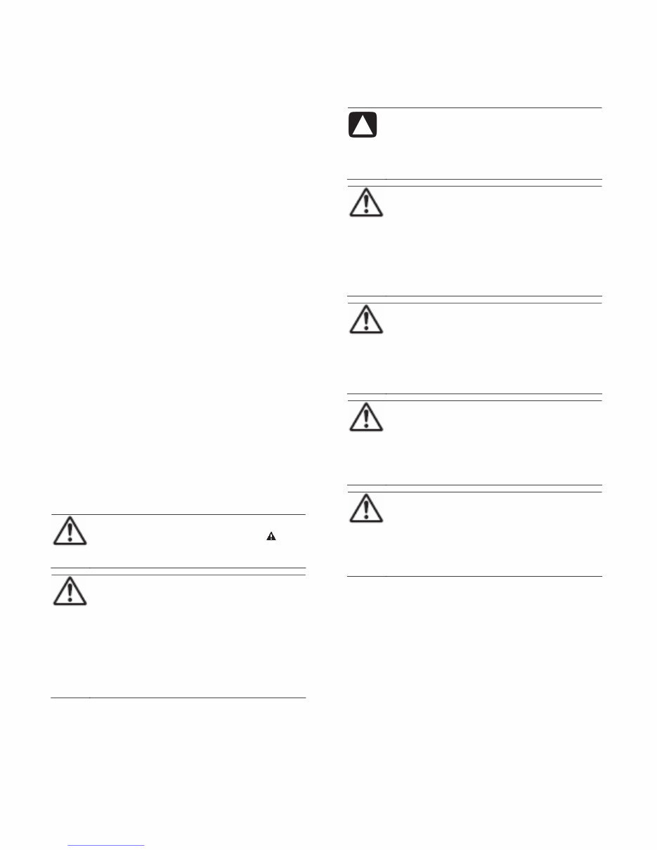
Warnings and Cautions
WARNING: Critical components having special
safety characteristics are identified with a by the
reference number in the parts list.
WARNING: Use of substitute replacement parts,
which do not have the same specified safety
characteristics, may create shock, fire, or other
hazards. Under no circumstances should the
original design be modified or altered without
written permission from HP. HP assumes no
liability, express or implied, arising out of any
unauthorized modification of design. The service
technician assumes all liability.
CAUTION: To ensure the continued reliability of this
product, use only the original manufacturer’s
replacement parts, which are listed with their part
numbers in the “Replaceable Parts List” section of this
service manual.
WARNING: All ICs and many other
semiconductors are susceptible to electrostatic
discharges (ESDs). Careless handling during repair
can be life-threatening. When repairing, make sure
that you are connected with the same potential as
the mass of the set by a wristband with resistance.
Keep components and tools also at this same
potential.
WARNING:
1 Never replace modules or other components while
the unit is turned on.
2 When making settings, use plastic rather than metal
tools. This will prevent any short circuits and the
danger of a circuit becoming unstable.
WARNING: To prevent electrical shock, do not use
the polarized AC plug with an extension cord,
receptacle, or the outlet unless the blades can be
fully inserted to prevent blade exposure. To prevent
electrical shock, match the wide blade or plug to a
wide slot and fully insert.
WARNING: When replacement parts are required,
be sure to use replacement parts specified by the
manufacturer or have the same characteristics as
the original part. Unauthorized substitutions may
result in fire, electric shock, or other hazards.
Important Service Safety Precautions
Downloaded from www.Manualslib.com manuals search engine

2 HP High-Definition LCD TV Service Manual
WARNINGS:
Safety regulations require that after a repair the set must be
returned in its original condition. In particular attention
should be paid to the following points:
NOTE: The wiring should be routed correctly and fixed
with the mounted cable clamps. The insulation of the main
leads should be checked for external damage.
• Do not touch the signal and the power connector while
this product is operating. Do not touch the EMI ground
part and the heat sink of the film filter.
• Do not supply a voltage higher than that specified to this
product. This may damage the product and may cause a
fire.
• Do not use this product in locations where the humidity
is extremely high, where it may be splashed with water,
or where flammable materials surround it. Do not install
or use the product in a location that does not satisfy the
specified environmental conditions. This may damage
the product and may cause a fire.
• If a foreign substance (such as water, metal, or liquid)
gets inside the panel module, immediately turn off the
power. Continuing to use the product, may cause fire or
electric shock.
• If the product emits smoke or an abnormal smell, or it
makes an abnormal sound, immediately turn off the
power. Continuing to use the product, may cause fire or
electric shock.
• Do not disconnect or connect the connector while power
to the product is on. It takes some time for the voltage to
drop to a sufficiently low level after the power has been
turned off. Confirm that the voltage has dropped to a
safe level before disconnecting or connecting the
connector.
• Do not pull out or insert the power cable from or to an
outlet with wet hands. It may cause electric shock.
• Do not damage or modify the power cable. It may cause
fire or electric shock.
• If the power cable is damaged, or if the connector is
loose, do not use the product; this can lead to fire or
electric shock.
• If the power connector or the connector of the power
cable becomes dirty or dusty, wipe it with a dry cloth.
Continuing to use the product may cause fire or electric
shock.
• The LCD module uses a high-voltage (maximum 450V
DC). Be cautious of electric shock and do not touch the
device circuitry when handling the LCD unit. Because
the capacitor of the device circuitry may remain charged
at the moment of power off, standing by for 1 minute is
strongly recommended before touching the device
circuitry.
• Use only with the cart, stand, tripod, bracket, or table
specified by the manufacturer, or sold with the
apparatus. When a cart is used, use caution when
moving the cart/apparatus combination to avoid injury
from tip-over.
Safe Handling and Servicing
The work procedures shown with the Warning
symbol are important for ensuring the safety of
the product and the servicing work. Be sure to
follow these instructions.
• Before starting the work, secure a sufficient workspace.
• At all times, other than when adjusting and checking the
product, be sure to turn off the Power button and
disconnect the power cable from the power source of the
TV during servicing.
• To prevent electric shock and breakage of PC board,
start the servicing work at least 30 seconds after the
main power has been turned off. Especially when
installing and removing the power supply board and the
SUS board, which involve high voltages, start servicing
at least 2 minutes after the main power has been turned
off.
• While the main power is on, do not touch any parts or
circuits other than the ones specified. The high-voltage
power supply block within the LCD module has a
floating ground. If any connection other than the one
specified is made between the measuring equipment and
the high voltage power supply block, it can result in
electric shock or activation of the leakage-detection
circuit breaker.
• When installing the LCD module into and removing it
from the packing carton, be sure to have at least two
people perform the work while being careful to ensure
that the flexible printed-circuit cable of the LCD module
does not get caught by the packing carton.
• When the surface of the panel comes into contact with
the cushioning materials, be sure that there is no foreign
matter on top of the cushioning materials. Foreign
matter may scratch the surface of the panel.
• Be sure to remove static electricity from your body
before handling the circuit board.
• Be sure to handle the circuit board by holding the large
parts such as the heat sink or transformer. Failure to
observe this precaution may result in the occurrence of
an abnormality in the soldered areas.
Downloaded from www.Manualslib.com manuals search engine
HP High-Definition LCD TV Service Manual 3
• Do not stack the circuit boards. Failure to observe this
precaution may result in problems resulting from
scratches on the parts, the deformation of parts, and
short-circuits due to residual electric charge.
• Routing the wires and fixing them in position must be
done in accordance with the original routing and fixing
configuration when servicing is completed. All the wires
are routed far away from the areas that become hot (such
as the heat sink). These wires are fixed in position with
the wire clamps so that the wires do not move, thereby
ensuring that they are not damaged and their materials
do not deteriorate over long periods of time. Therefore,
route the cables and fix the cables to the original
position and states using the wire clamps.
• Perform a safety check when servicing is completed.
Verify that the peripherals of the serviced points have
not undergone any deterioration during servicing. Also
verify that the screws, parts, and cables removed for
servicing purposes have all been returned to their proper
locations in accordance with the original setup.
• A glass plate protects the LCD display. This glass plate
can be cleaned with a slightly moist cloth. If dirt appears
between the glass plate and the LCD display panel have
only a qualified service employee clean it.
Repair Tips
WARNING: All ICs and many other
semiconductors are susceptible to electrostatic
discharges (ESDs). Careless handling during repair
can be life-threatening. When repairing, make sure
that you are connected with the same potential as
the mass of the unit via a wrist wrap with
resistance. Keep components and tools also at the
same potential.
About Lead-Free Solder
NOTE: LEAD IS LISTED AS (PB) IN THE PERIODIC
TABLE OF THE ELEMENTS. IN THE INFORMATION
THAT FOLLOWS, PB WILL REFER TO LEAD
SOLDER, AND PBF WILL REFER TO LEAD-FREE
SOLDER. THE LEAD-FREE SOLDER USED IN OUR
MANUFACTURING PROCESS AND DISCUSSED
HERE IS (SN+AG+CU). THAT IS TIN (SN), SILVER
(AG), AND COPPER (CU), ALTHOUGH OTHER
TYPES ARE AVAILABLE.
This model is manufactured using Pb-free solder for the
sake of environmental conservation. For service and repair
work, we suggest using Pb-free solder as well, although Pb
solder may be used.
PCBs manufactured using Pb-free solder have the sign
stamped on the PCB.
CAUTIONS:
• Pb-free solder has a higher melting point than Pb solder.
Typically the melting point is 50–70ºF
(30–40°C) higher. Use a high temperature soldering
iron. Adjust your solder tool so that a temperature
around 360–380ºC is reached and stabilized at the solder
joint. Heating time of the solder joint should not exceed
4 seconds. Avoid temperatures above 400ºC; wear-out of
tips will rise drastically and flux-fluid will be destroyed.
• Pb-free solder will tend to splash when heated too high
(about 1,100ºF or 600ºC).
• Mix of Pb-free solder Tin (SN)/parts with leaded
soldering Tin (SN) in/parts is possible but not
recommended. If you have to use Pb solder, completely
remove all of the Pb-free solder on the pins or solder
area before applying Pb solder. If this is not practical, be
sure to heat the Pb-free solder until it melts, before
applying Pb solder.
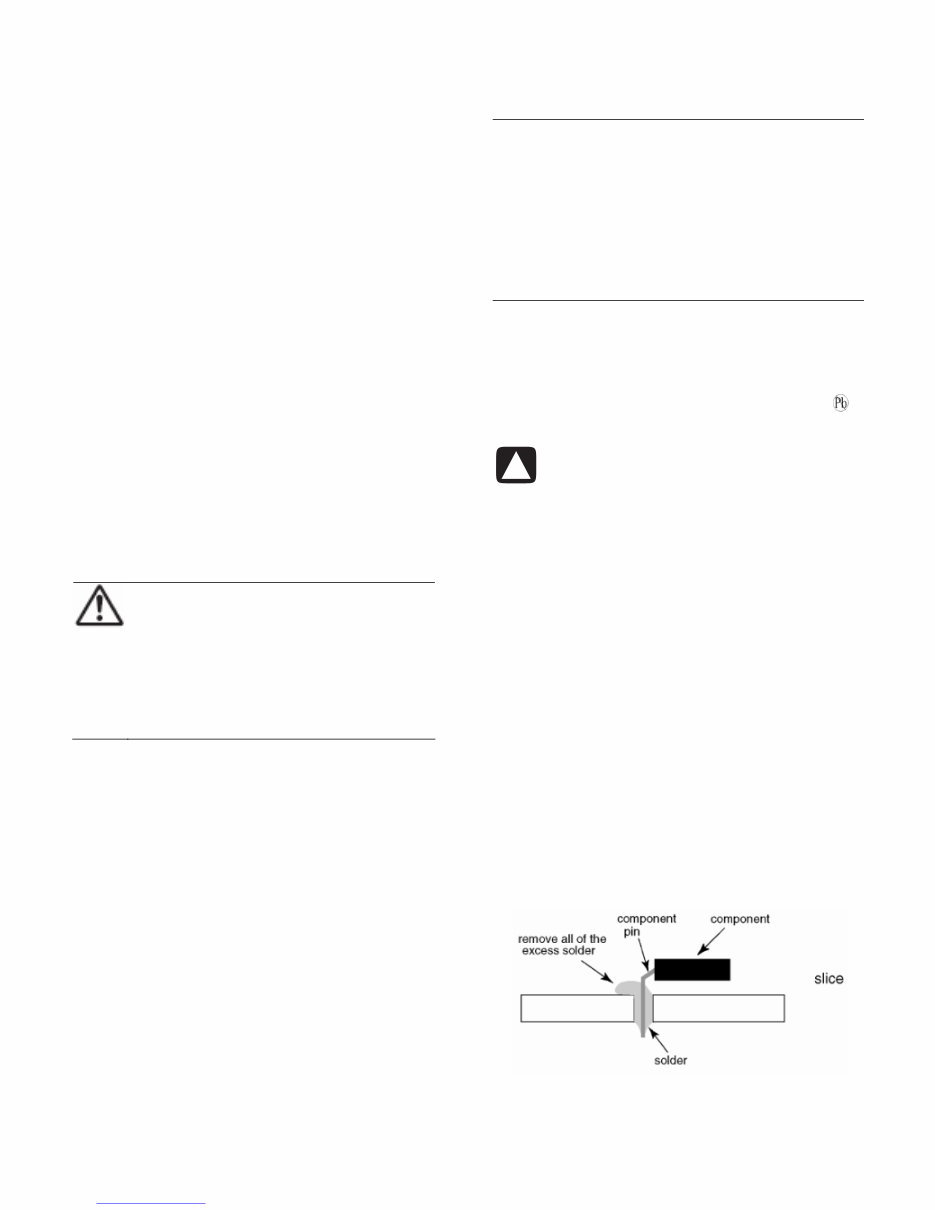
• After applying Pb-free solder to double-layered boards,
check the component side for excess solder that may
flow onto the opposite side (see the following
illustration).
Downloaded from www.Manualslib.com manuals search engine
4 HP High-Definition LCD TV Service Manual
• Special information for Pb-free BGA-ICs: These ICs
will be delivered in so-called dry-packaging to protect
the IC against moisture and with the Pb-free logo on it.
This packaging may only be opened shortly before it is
used (soldered). Otherwise the body of the IC gets wet
inside, and during the heating time the structure of the
IC will be destroyed from steam pressure. If the
packaging was opened before usage the IC has to be
heated up for about 90 hours to dry. Make sure you use
ESD protection!
Suggested Pb-Free Solder
Several kinds of Pb-free solder (some shown in the
following illustration) are available for purchase. This
product uses Sn+Ag+Cu (tin (SN), silver (AG), copper
(CU)) solder. However, Sn+Cu (tin (SN), copper (Cu)),
Sn+Zn+Bi (tin (SN), zinc (Zn), bismuth (Bi)) solder can
also be used.
Servicing of Surface-Mounted Devices
(SMDs)
CAUTIONS:
General cautions on handling and storage:
• Oxidation on the terminals of SMDs results in poor
soldering. Do not handle SMDs with bare hands.
• Avoid using storage places that are sensitive to
oxidation, such as places with sulphur or chlorine gas,
direct sunlight, high temperatures, or a high degree of
humidity. The capacitance or resistance value of the
SMDs may be affected by these conditions.
• Rough handling of circuit boards containing SMDs may
cause damage to the components as well as the circuit
boards. Circuit boards containing SMDs should never be
bent or flexed. Different circuit board materials expand
and contract at different rates when heated or cooled and
the components and/or solder connections may be
damaged due to the stress.
• Never rub or scrape chip components as this may cause
the value of the component to change. Similarly, do not
slide the circuit board across any surface.
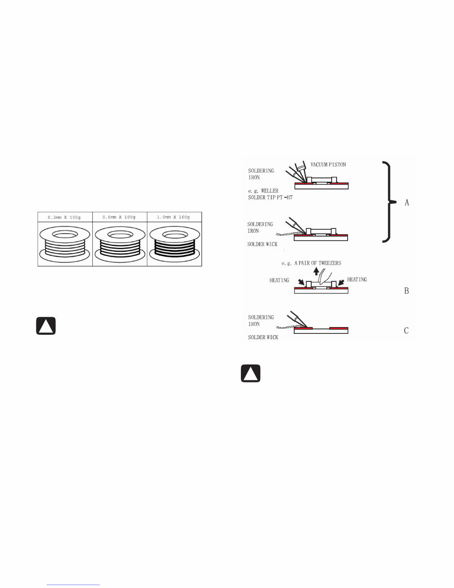
Removal of SMDs
1 Heat the solder (for 2 to 3 seconds) at each terminal of
the chip. By means of soldier wick and a slight
horizontal force, small components can be removed with
the soldering iron. They can also be removed with a
solder sucker (A).
2 While holding the SMD with a pair of tweezers, take it
off gently using the soldering iron’s heat applied to each
terminal (B).
3 Remove the excess solder on the solder lands by means
of soldier wick or a solder sucker (C).
CAUTIONS:
• When handling the soldering iron, use suitable pressure
and be careful.
• When removing the chip, do not use undue force with
the pair of tweezers.
• The soldering iron to be used (approx. 30 W) should
preferably be equipped with a thermal control (soldering
temperature: 360º to 380º C).
• Once removed, the chip cannot be reused.
Downloaded from www.Manualslib.com manuals search engine
You're Reading a Preview
What's Included?
 Lifetime Access
Fast Download Speeds
Online & Offline Access
Access PDF Contents & Bookmarks
Full Search Facility
Print one or all pages of your manual
$28.99
HP LT3200 LT3700 LT4200 LT4700 Service Manual
Viewed 80 Times Today

What's Included?
Lifetime Access
Fast Download Speeds
Online & Offline Access
Access PDF Contents & Bookmarks
Full Search Facility
Print one or all pages of your manual
$28.99

Secure transaction
What's Included?
Lifetime Access
Fast Download Speeds
Online & Offline Access
Access PDF Contents & Bookmarks
Full Search Facility
Print one or all pages of your manual
Description
The HP LT3200 LT3700 LT4200 LT4700 Service Manual is an essential resource for both professional mechanics and DIY enthusiasts. It provides comprehensive coverage of important service safety precautions, product information, and specifications. The manual also includes detailed guidance on basic operation, replaceable parts, removal and replacement procedures, diagnostics, troubleshooting, firmware update procedure, and LCD panel specifications.


