2 PRS-500 TABLE OF CONTENTS 1. SERVICING NOTE .................................................. 3 2. GENERAL ................................................................... 5 3. DISASSEMBLY 3-1. Disassembly Flow ........................................................... 6 3-2. Soft Cover ........................................................................ 7 3-3. B Case Assy ..................................................................... 7 3-4. A Case Assy ..................................................................... 8 3-5. Magnet ............................................................................. 9 3-6. MAIN Board .................................................................... 9 3-7. MS FLEXIBLE Board, Chassis ...................................... 10 3-8. Ink Indicator Element Assy ............................................. 10 4. TEST MODE ............................................................... 11 5. ELECTRICAL ADJUSTMENT ............................. 12 6. DIAGRAMS 6-1. Block Diagram ................................................................ 14 6-2. Printed Wiring Boards – MAIN, DC Board (Side A) – ........................................ 15 6-3. Printed Wiring Boards – MAIN, DC Board (Side B) – ........................................ 16 6-4. Schematic Diagram – MAIN Board (1/10) – ................. 17 6-5. Schematic Diagram – MAIN Board (2/10) – ................. 18 6-6. Schematic Diagram – MAIN Board (3/10) – ................. 19 6-7. Schematic Diagram – MAIN Board (4/10) – ................. 20 6-8. Schematic Diagram – MAIN Board (5/10) – ................. 21 6-9. Schematic Diagram – MAIN Board (6/10) – ................. 22 6-10. Schematic Diagram – MAIN Board (7/10) – ................. 23 6-11. Schematic Diagram – MAIN Board (8/10) – ................. 24 6-12. Schematic Diagram – MAIN Board (9/10) – ................. 25 6-13. Schematic Diagram – MAIN Board (10/10), DC Board – .............................. 26 7. EXPLODED VIEWS 7-1. Overall Assy Section ....................................................... 50 7-2. A Case Assy Section ........................................................ 51 8. ELECTRICAL PARTS LIST .................................. 52 UNLEADED SOLDER Boards requiring use of unleaded solder are printed with the lead- free mark (LF) indicating the solder contains no lead. (Caution: Some printed circuit boards may not come printed with the lead free mark due to their particular size) : LEAD FREE MARK Unleaded solder has the following characteristics. • Unleaded solder melts at a temperature about 40 °C higher than ordinary solder. Ordinary soldering irons can be used but the iron tip has to be applied to the solder joint for a slightly longer time. Soldering irons using a temperature regulator should be set to about 350 °C. Caution: The printed pattern (copper foil) may peel away if the heated tip is applied for too long, so be careful! • Strong viscosity Unleaded solder is more viscou-s (sticky, less prone to flow) than ordinary solder so use caution not to let solder bridges occur such as on IC pins, etc. • Usable with ordinary solder It is best to use only unleaded solder but unleaded solder may also be added to ordinary solder. Flexible Circuit Board Repairing • Keep the temperature of the soldering iron around 270 °C during repairing. • Do not touch the soldering iron on the same conductor of the circuit board (within 3 times). • Be careful not to apply force on the conductor when soldering or unsoldering. Notes on chip component replacement • Never reuse a disconnected chip component. • Notice that the minus side of a tantalum capacitor may be damaged by heat. • Microsoft, Windows, Windows NT and Windows Media are trademarks or registered trademarks of Microsoft Corporation in the United States and/or other countries. • Adobe and Adobe Reader are trademarks or registered trademarks of Adobe Systems Incorporated in the United States and/or other countries. • MPEG Layer-3 audio coding technology and patents licensed from Fraunhofer IIS and Thomson. CAUTION Danger of explosion if battery is incorrectly replaced. Replace only with the same or equivalent type. Downloaded from www.Manualslib.com manuals search engine
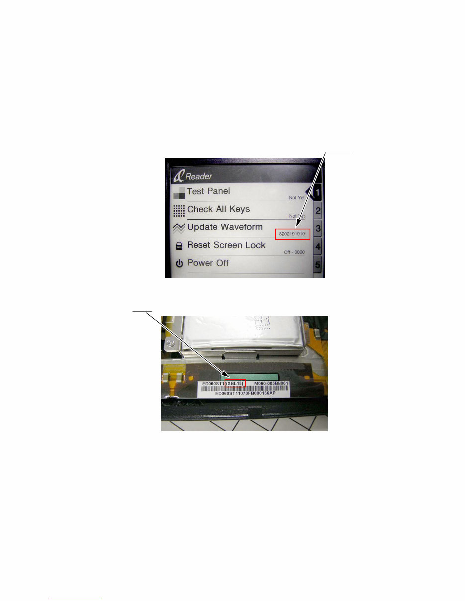
3 PRS-500 SECTION 1 SERVICING NOTE NOTES WHEN REPLACING THE INK INDICATOR ELEMENT ASSY, MAIN BOARD AND FLASH ROM (IC1611) When the INK INDICATOR ELEMENT ASSY, MAIN board, or FLASH ROM (IC1611) is replaced, you need to change the LUT. Rewriting the LUT The LUT is exclusive for each lot number of the INK INDICATOR ELEMENT ASSY. Therefore, when replacing the MAIN board, display panel, or FLASH ROM, you need to rewrite the LUT. However, rewriting is not required if the lot number is the same. Location where the LUT is stored • IC1611 How to check the version of the stored LUT • When you insert the Memory Stick in which the exclusive file is stored, the Test Mode is established. Check the current LUT version displayed at the right side of Update Waveform as in the screen below. The LUT version is “ 8202191919” in this example. How to check the lot number of the display panel • The lot number is written on the label on the flexible card wire. The lot number is “ XBL15” in the picture below. How to change the LUT • Copy the LUT file you want to update to the folder under “/Sony Reader/software” in the Memory Stick exclusive for the Test Mode, and then change the name to “lut.bin”. Execute Test Mode No.3 “Update Waveform”. The LUT will be updated in about 10 seconds, and the LUT version display will also change. • For the LUT version and the LUT file corresponding to the lot number of the panel, refer to Technical News. NOTE: • To create the Memory Stick exclusive for the Test Mode, refer to TEST MODE (Page 11). • For the VCOM adjustment value of RV601 for each lot, refer to Electrical Adjustment (Page 12). Downloaded from www.Manualslib.com manuals search engine
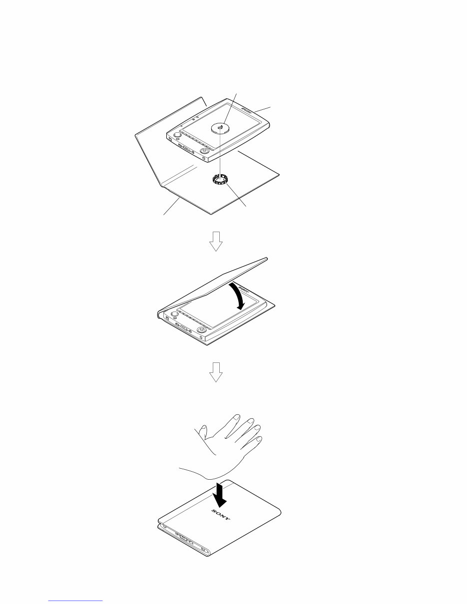
4 PRS-500 Place the main overall assy on the soft cover by aligning the position of the claws. Close the soft cover. Press on the back side of the soft cover (the side with the SONY logo) to lock the claws. * Do not press on the front side of the soft cover. Doing so may the LCD screen. soft cover main overall assy claw claw NOTE OF HOW TO SET THE SOFT COVER Downloaded from www.Manualslib.com manuals search engine
5 PRS-500 SECTION 2 GENERAL This section is extracted from instruction manual. Downloaded from www.Manualslib.com manuals search engine
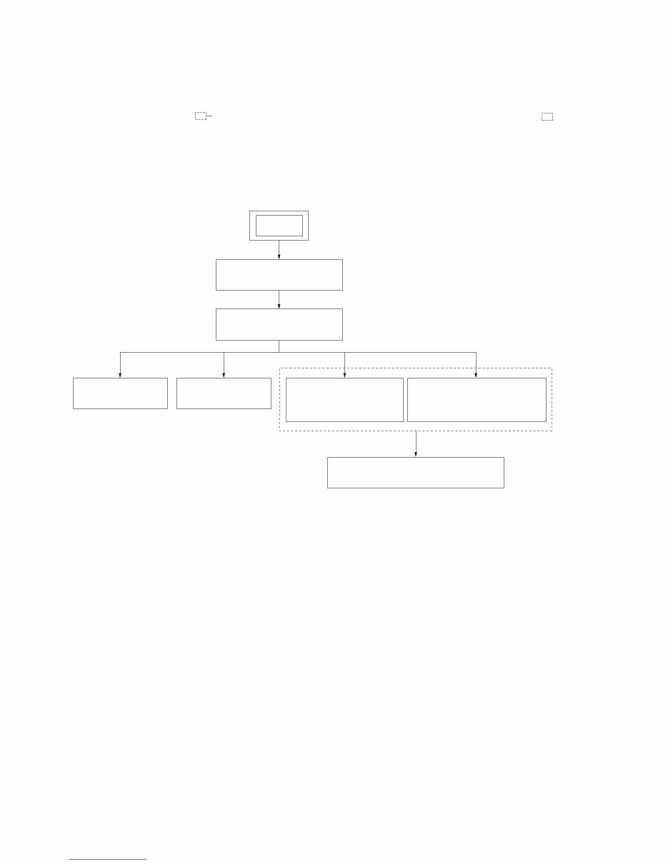
6 PRS-500 SECTION 3 DISASSEMBLY Note 3-1. DISASSEMBLY FLOW 3-2. SOFT COVER (Page 7) SET 3-3. B CASE ASSY (Page 7) 3-8. INK INDICATOR ELEMENT ASSY (Page 10) 3-5. MAGNET (Page 9) 3-6. MAIN BOARD (Page 9) 3-7. MS FLEXIBLE BOARD, CHASSIS (Page 10) 3-4. A CASE ASSY (Page 8) • This set can be disassembled in the order shown below. • The dotted square with arrow ( ) prompts you to move to the next job when all of the works within the dotted square ( ) are completed. Downloaded from www.Manualslib.com manuals search engine
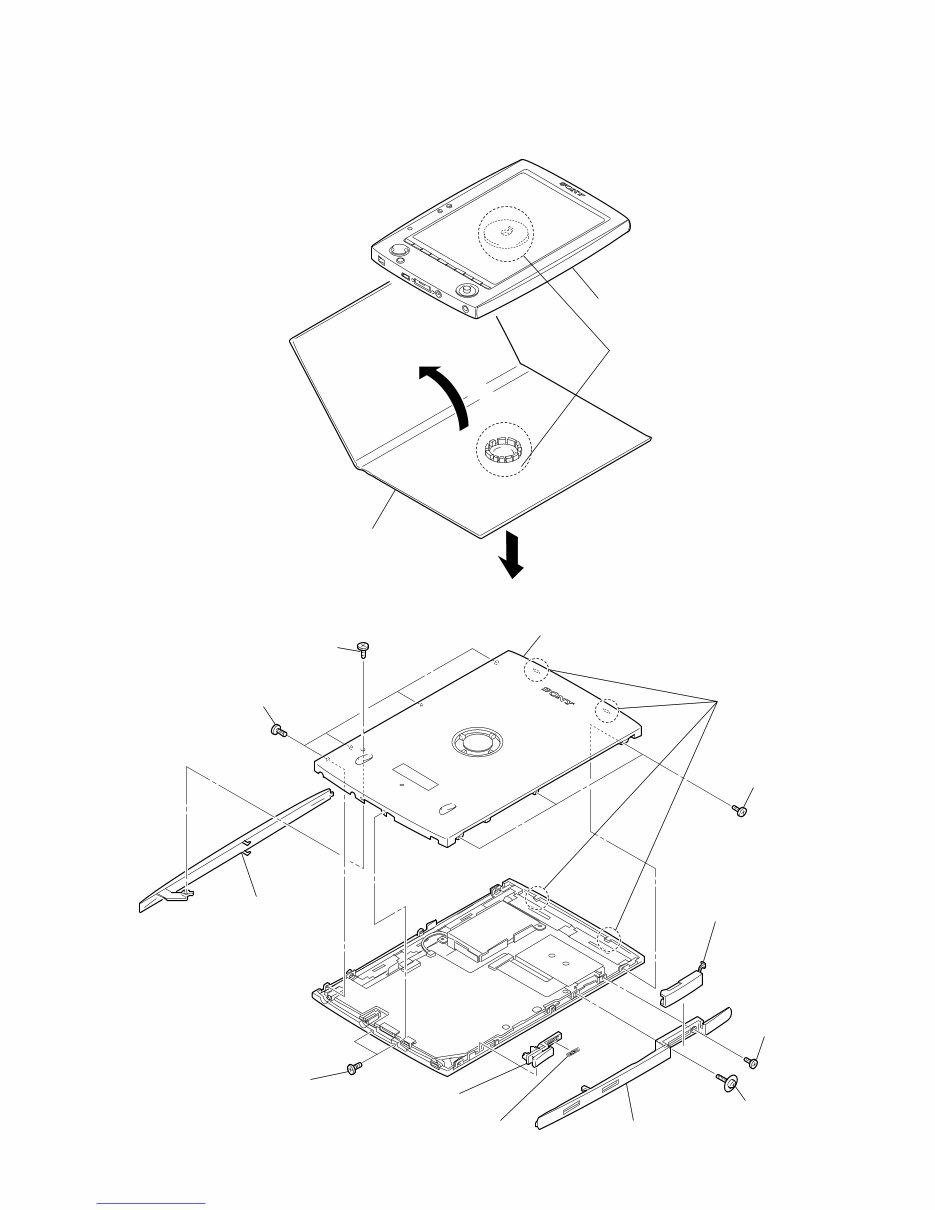
7 PRS-500 Note: Follow the disassembly procedure in the numerical order given. 3-2. SOFT COVER 3-3. B CASE ASSY 1 3 2 four claws 4 main overall assy 5 soft cover 1 tapping screw (1.7) 3 two fasteners (M1.4 × 3) 8 three fasteners (M1.4 × 3) 9 four fasteners (M1.4 × 3) q; two claws qd B case assy 4 washerhead (+P) screw (M1.4 × 3.5) 5 fastener (M1.4 × 3) 6 ornamental plate (L) 7 memory slot assy 2 ornamental plate (R) qs compression spring qa power key Downloaded from www.Manualslib.com manuals search engine
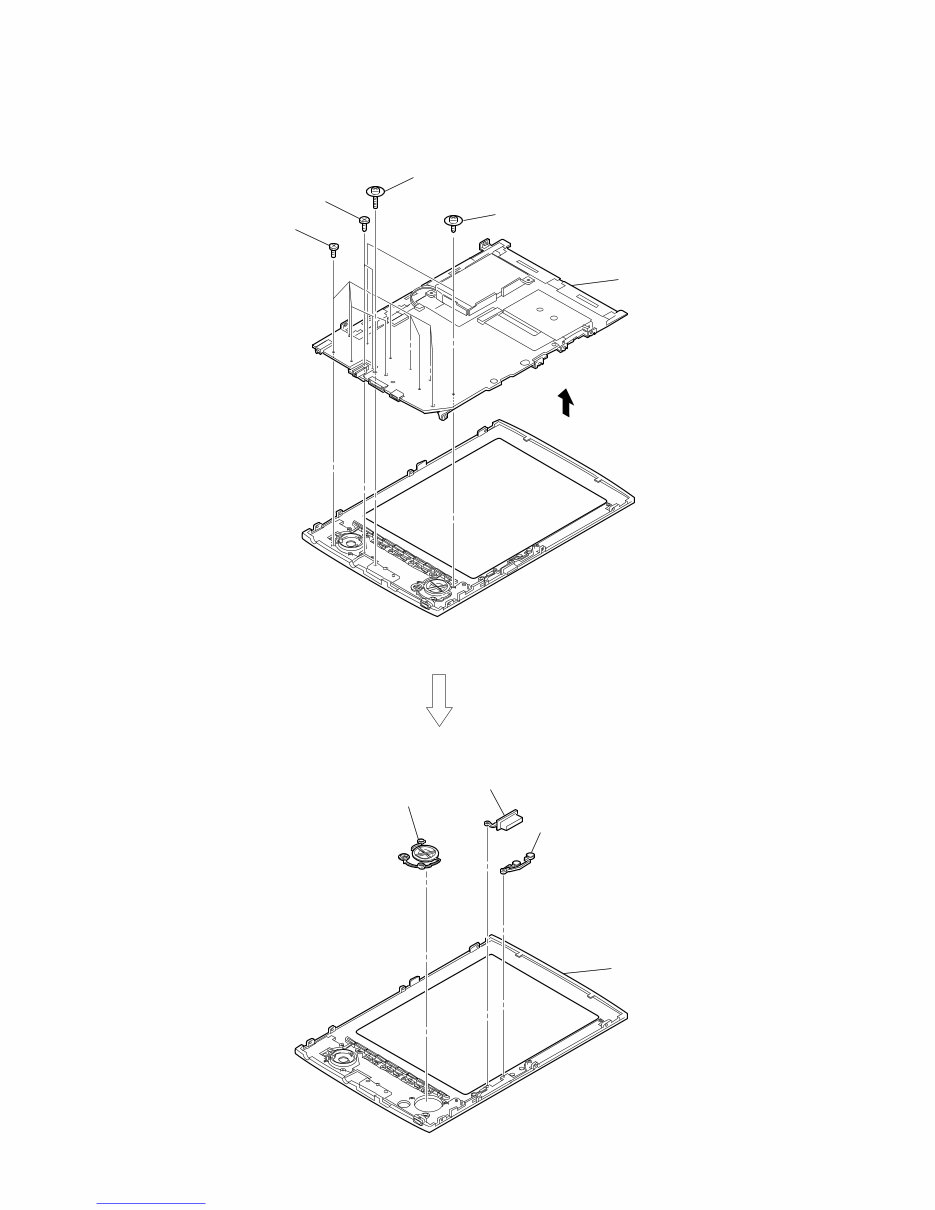
8 PRS-500 3-4. A CASE ASSY 5 q; A case assy 6 MAIN board, INK indicator element 1 two tapping screws (B) (1.4 × 8) 3 two screws (M1.4) 4 washerhead (+P) screw (M1.4 × 3.5) 2 nine tapping screws (1.4) 9 key top (3) 8 key top (5) 7 key top (2) Downloaded from www.Manualslib.com manuals search engine
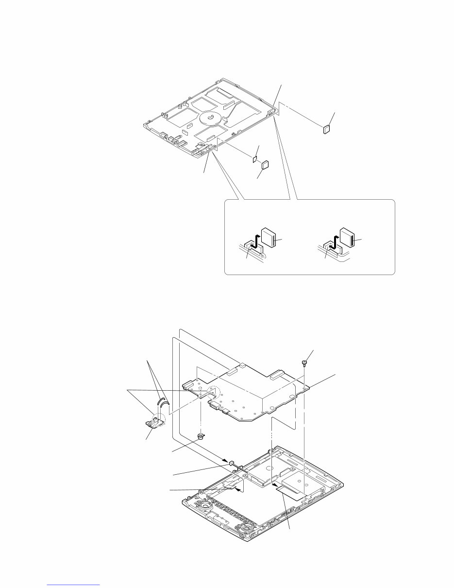
9 PRS-500 3-5. MAGNET 3-6. MAIN BOARD 2 magnet Bottom side Bottom side Fit the bottom side groove with a magnet painted red line and fit the upper side groove with a magnet painted black line. Press each magnet against A site and B site as below. B red line black line A Upper side Upper side 3 magnet 1 sheet (magnet) PRECAUTION DURING MAGNET INSTALLATION 5 key top (4) 4 three screws (M1.4 × 2) 2 ink indicator element (CN1601) 3 MS flexible board (CN602) 1 connector (CN401) 9 MAIN board 8 DC board assy 6 Remove soldering from the four points. 7 two connection terminals Downloaded from www.Manualslib.com manuals search engine
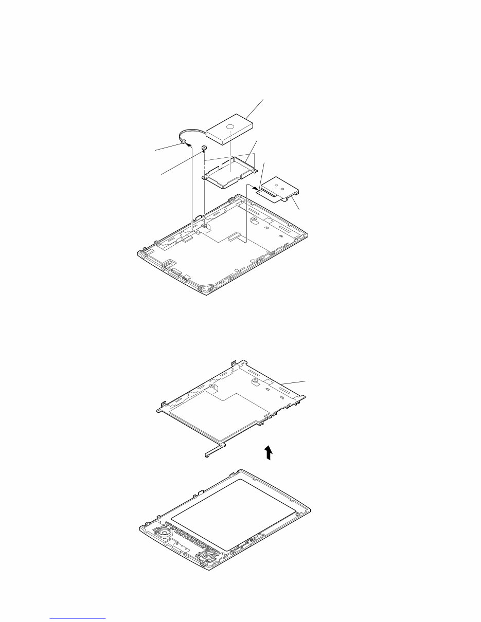
10 PRS-500 3-7. MS FLEXIBLE BOARD, CHASSIS 1 connector (CN602) 2 MS flexible board 4 battery bracket 6 battery lithium ion storage 5 connector (CN401) 3 two screws (M1.4 × 2) 2 ink indicator element assy 1 3-8. INK INDICATOR ELEMENT ASSY Downloaded from www.Manualslib.com manuals search engine
Why replace when you can upgrade or repair? This service manual is used by the Official Certified Sony Technicians. It will help you to troubleshoot and repair your Reader!
You will learn about:
Product Specifications
Disassembly & Reassembly
Test Modes
Adjustments
System Diagrams
Exploded Views
Parts List/ Parts Catalog
This manual is very detailed and illustrated with pictures and step-by-step instructions on how to repair/service this device the best way there is!
Please note this is the OFFICIAL manual in PDF format, no scanned-in or bootlegged copy. This manual is made in the highest resolution, so when you print the pages you need it is all in great quality!
You can easily print this manual from any printer and any computer!
***INSTANT access*** After your payment, you will have instant access to your manual. No shipping fee, no waiting on postal delivery, you can start doing your repairs right away!
Specifications
Language: English
Format: PDF
Platform: Windows and MAC
Looking for a service manual but can't find it anywhere? Please contact us with your request! As you can see we've got the largest & most comprehensive service manual database out there, so a good chance we can help you out!
Questions/Remarks/Problems/Uncertainties/Information: Please do NOT HESITATE to mail us! We ALWAYS reply to answer all your questions!