— 2 — DSC-H5_L2 SPECIFICATIONS These specifications are extracted from User’s Guide/ Troubleshooting of DSC-H5 (2-673-176-11 (1)). Camera [System] Image device 7.20 mm (1/2.5 type) color CCD, Primary color filter Total pixel number of camera Approx. 7 410 000 pixels Effective pixel number of camera Approx. 7 201 000 pixels Lens Carl Zeiss Vario-Tessar 12× zoom lens f = 6.0 – 72.0 mm (36 – 432 mm when converted to a 35 mm still camera) F2.8 – 3.7 Exposure control Automatic exposure, Shutter speed priority, Aperture priority, Manual exposure, Scene Selection (7 modes) White balance Automatic, Daylight, Cloudy, Fluorescent, Incandescent, Flash, One push File format (DCF compliant) Still images: Exif Ver. 2.21 JPEG compliant, DPOF compatible Movies: MPEG1 compliant (Monaural) Recording media Internal Memory (30 MB) “Memory Stick Duo” Flash Flash range (ISO set to Auto): approx. 0.3 m to 9.0 m (11 7/ 8 inches to 29 feet 6 3/8 inches) (W)/approx. 0.9 m to 6.8 m (35 1/2 inches to 22 feet 3 3/ 4 inches) (T) Viewfinder Electric viewfinder (color) [Input and Output connectors] A/V OUT jack (Monaural) Minijack Video: 1 Vp-p, 75 Ω, unbalanced, sync negative Audio: 327 mV (at a 47 kΩ load) Output impedance 2.2 kΩ USB jack mini-B USB communication Hi-Speed USB (USB 2.0 compliant) [LCD screen] LCD panel 7.5 cm (3.0 type) TFT drive Total number of dots 230 400 (960×240) dots [Finder] Panel 0.5 cm (0.2 type) color Total number of dots Approx. 200 000 dots equivalent [Power, general] Power HR 15/51:HR6 (size AA) Nickel-Metal Hydride batteries (2), 2.4 V LR6 (size AA) alkaline batteries (2), 3 V ZR6 (size AA) Oxy Nickel Primary Battery (2), 3 V AC-LS5K AC Adaptor 4.2 V Power consumption (during shooting with the LCD screen) 1.4 W Operating temperature 0 to 40°C (32 to 104°F) Storage temperature –20 to +60°C (–4 to +140°F) Dimensions 113.2×83.0×94.0 mm (4 1/2 inches × 3 3/8 inches × 3 3/4 inches) (W/H/D, excluding protrusions) Mass Approx. 554 g (1 lb 3.5 oz) (including two batterries, shoulder strap, adaptor ring, lens hood, lens cap, etc.) Microphone Electret condenser microphone Speaker Dynamic speaker Exif Print Compatible PRINT Image Matching III Compatible PictBridge Compatible BC-CS2A/CS2B Ni-MH battery charger Power requirements AC 100 to 240 V, 50/60 Hz, 3W Output voltage AA: DC 1.4V 400 mA × 2 AAA: DC 1.4 V 160 mA × 2 Operating temperature 0 to +40°C (+32 to +104°F) Storage temperature –20 to +60°C (–4 to +140°F) Dimensions Approx. 713091 mm (2 7/8×1 3/16×3 5/8 inches) (W/H/D) Mass Approx. 90 g (3 oz) Design and specifications are subject to change without notice.
— 3 — DSC-H5_L2 1. Check the area of your repair for unsoldered or poorly-soldered connections. Check the entire board surface for solder splashes and bridges. 2. Check the interboard wiring to ensure that no wires are "pinched" or contact high-wattage resistors. 3. Look for unauthorized replacement parts, particularly transistors, that were installed during a previous repair. Point them out to the customer and recommend their replacement. 4. Look for parts which, through functioning, show obvious signs of deterioration. Point them out to the customer and recommend their replacement. 5. Check the B+ voltage to see it is at the values specified. 6. Flexible Circuit Board Repairing • Keep the temperature of the soldering iron around 270˚C during repairing. • Do not touch the soldering iron on the same conductor of the circuit board (within 3 times). • Be careful not to apply force on the conductor when soldering or unsoldering. Unleaded solder Boards requiring use of unleaded solder are printed with the lead- free mark (LF) indicating the solder contains no lead. (Caution: Some printed circuit boards may not come printed with the lead free mark due to their particular size.) : LEAD FREE MARK Unleaded solder has the following characteristics. • Unleaded solder melts at a temperature about 40°C higher than ordinary solder. Ordinary soldering irons can be used but the iron tip has to be applied to the solder joint for a slightly longer time. Soldering irons using a temperature regulator should be set to about 350°C. Caution: The printed pattern (copper foil) may peel away if the heated tip is applied for too long, so be careful! • Strong viscosity Unleaded solder is more viscous (sticky, less prone to flow) than ordinary solder so use caution not to let solder bridges occur such as on IC pins, etc. • Usable with ordinary solder It is best to use only unleaded solder but unleaded solder may also be added to ordinary solder. SAFETY CHECK-OUT After correcting the original service problem, perform the following safety checks before releasing the set to the customer. SAFETY-RELATED COMPONENT WARNING!! COMPONENTS IDENTIFIED BY MARK 0 OR DOTTED LINE WITH MARK 0 ON THE SCHEMATIC DIAGRAMS AND IN THE PARTS LIST ARE CRITICAL TO SAFE OPERATION. REPLACE THESE COMPONENTS WITH SONY PARTS WHOSE PART NUMBERS APPEAR AS SHOWN IN THIS MANUAL OR IN SUPPLEMENTS PUBLISHED BY SONY. ATTENTION AU COMPOSANT AYANT RAPPORT À LA SÉCURITÉ! LES COMPOSANTS IDENTIFÉS PAR UNE MARQUE 0 SUR LES DIAGRAMMES SCHÉMATIQUES ET LA LISTE DES PIÈCES SONT CRITIQUES POUR LA SÉCURITÉ DE FONCTIONNEMENT. NE REMPLACER CES COMPOSANTS QUE PAR DES PIÈSES SONY DONT LES NUMÉROS SONT DONNÉS DANS CE MANUEL OU DANS LES SUPPÉMENTS PUBLIÉS PAR SONY. CAUTION : Danger of explosion if battery is incorrectly replaced. Replace only with the same or equivalent type.
— 4 — DSC-H5_L2 TABLE OF CONTENTS 1. SERVICE NOTE 1-1. DESCRIPTION ON SELF-DIAGNOSIS DISPLAY ······1-1 1-2. METHOD FOR COPYING OR ERASING THE DATA IN INTERNAL MEMORY ·················································· 1-2 1-3. PRECAUTION ON REPLACING THE SY-150 BOARD ··········································································· 1-3 1-4. VIDEO OUT DEFAULT DATA CHECK·······················1-3 1-5. INITIAL LANGUAGE DATA CHECK··························1-3 2. DISASSEMBLY 2-1. DISASSEMBLY ······························································2-3 3. BLOCK DIAGRAMS 3-1. OVERALL BLOCK DIAGRAM (1/2) ···························3-1 3-2. OVERALL BLOCK DIAGRAM (2/2) ···························3-2 3-3. POWER BLOCK DIAGRAM (1/2) ································3-3 3-4. POWER BLOCK DIAGRAM (2/2) ································3-4 4. PRINTED WIRING BOARDS AND SCHEMATIC DIAGRAMS 4-1. FRAME SCHEMATIC DIAGRAM································4-1 4-2. SCHEMATIC DIAGRAMS ············································4-5 4-3. PRINTED WIRING BOARDS ····································· 4-25 4-4. MOUNTED PARTS LOCATION ·································4-32 5. REPAIR PARTS LIST 5-1. EXPLODED VIEWS ······················································ 5-3 5-2. ELECTRICAL PARTS LIST ········································5-10
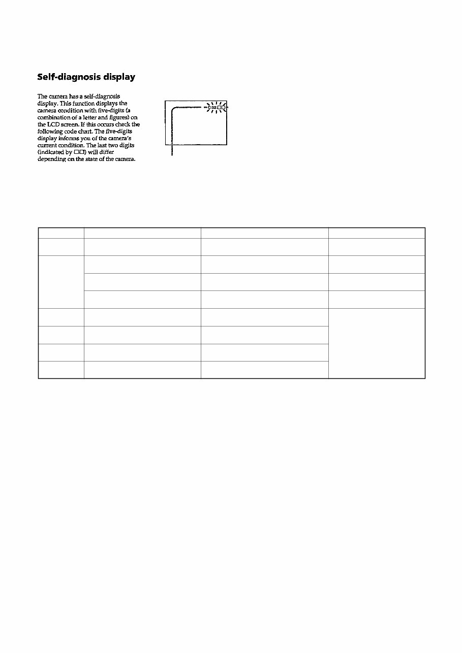
1-1 DSC-H5_L2 Note : After repair, be sure to execute the “Initialize” of the setup screen. Self-diagnosis display • C: ss: ss The contents which can be handled by customer, are displayed. • E: ss: ss The contents which can be handled by engineer, are displayed. 1. SERVICE NOTE 1-1. DESCRIPTION ON SELF-DIAGNOSIS DISPLAY Display Code C:32:ss C:13:ss Countermeasure Turn the power off and on again. Format the “Memory Stick” or internal memory. Insert a new “Memory Stick”. Cause Trouble with hardware. “Memory Stick” or internal memory is unformatted. “Memory Stick” is broken. Caution Display During Error SYSTEM ERROR FORMAT ERROR MEMORY STICK ERROR E:61:ss E:91:ss Checking of lens drive circuit. Checking of flash unit or replacement of flash unit. (Note) Abnormality when flash is being charged. Batteries are pack is not inserted correctly. Insert a batteries correctly. Trouble with internal mamory. Turn the power off and on again. When failed in the focus zoom initialization. INTERNAL MEMORY ERROR E:92:ss _ E:62:ss Inspect angular velocity sensor peripheral circuits. Steady shot function does not work well.
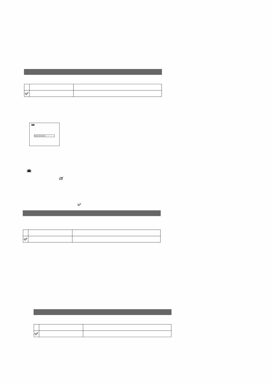
1-2 DSC-H5_L2 1-2. METHOD FOR COPYING OR ERASING THE DATA IN INTERNAL MEMORY The data can be copied/erased by the operations on the Setup screen. (When erasing the data, execute formatting the internal memory.) Note: 1 When replacing the SY-150 board, erase the data in internal memory of the board before replacement. Note: 2 When replacing the SY-150 board or the IC202 on the SY-150 board, execute formatting and initialize the internal memory after replacement. • PROCESS AFTER FIXING FLASH ERROR When “FLASH error” (Self-diagnosis Code E : 91 : ** ) occurs, to prevent any abnormal situation caused by high voltage, setting of the flash is changed automatically to disabling charge and flash setting. After fixing, this setting needs to be deactivated. Flash error code can be initialized by the operations on the Setup screen. Method for Initializing the Flash Error Code Initializes the setting to the default setting. 1 Select [OK] with v on the control button, then press z. The message “Initialize all settings Ready?” appears. 2 Select [OK] with v, then press z. The settings are reset to the default setting. Make sure that the power is not disconnected during resetting. Initialize OK See the following procedure. Cancel Cancels the resetting. Method for copying the data in internal memory Method for formatting the internal memory This item does not appear when a “Memory Stick Duo” is inserted in the camera. The default settings are marked with . Formats the internal memory. • Note that formatting irrevocably erases all data in the internal memory, including even protected images. 1 Select [OK] with v on the control button, then press z. The message “All data in internal memory will be erased Ready?” appears. 2 Select [OK] with v, then press z. The format is complete. Format OK See the following procedure. Cancel Cancels the formatting. Copies all images in the internal memory to a “Memory Stick Duo”. 1 Insert a “Memory Stick Duo” having 32 MB or larger capacity. 2 Select [OK] with v on the control button, then press z. The message “All data in internal memory will be copied Ready?” appears. 3 Select [OK] with v, then press z. Copying starts. • Use a fully charged Nickel-Metal Hydride battery or the AC Adaptor (not supplied). If you attempt to copy image files using a batteries with little remaining charge, the batteries may run out, causing copying to fail or possibly corrupting the data. • You cannot copy individual images. • The original images in the internal memory are retained even after copying. To delete the contents of the internal memory, remove the “Memory Stick Duo” after copying, then execute the [Format] command in (Internal Memory Tool). • You cannot select a folder copied on a “Memory Stick Duo”. • Even if you copy data, a (Print order) mark is not copied. Copy OK See the following procedure. Cancel Cancels the copying. Copying 102_COPY
1-3E DSC-H5_L2 1-3. PRECAUTION ON REPLACING THE SY-150 BOARD 1-4. VIDEO OUT DEFAULT DATA CHECK 1-5. INITIAL LANGUAGE DATA CHECK • The Repair Board has already been adjusted. Re-initialization or EVR data copy from the set before repair is not required. • Perform “VIDEO OUT Default Data Check” and “Initial Language Data Check” mentioned below, and also the adjustment items necessary after SY Board replacement. When you replace to the repairing board, the written data of repairing board also might be changed to original setteing because of broadcast system (NTSC/PAL). When the data has changed because of board replaceing etc., check the default data of VIDEO OUT if destination code is right. If not, rewrite to the right value. VIDEO OUT Default Data Page Address Data NTSC PAL 4F 8D 00 01 Writing Method: 1) Select page: 00, address: 01, and set data: 01. 2) Select page: 4F, address: 8D, and set data: 00 (NTSC) or data: 01 (PAL). 3) Select page: 40, address: 38, and set data: 00. 4) Click [Save] on the SEUS screen. 5) Select page: 80, address: 34, and check that the data is “00”. 6) Select page: 80, address: 30, and check that the data is “00”. 7) Select page: 00, address: 01, and set data: 00. If the SY-150 board was replaced, initial language setting may be changed. Accordingly, change the following data so as to set same initial language as that of the set distributing in each region. Initial language: Language displayed at the next starting if the setting of Setup menu was reset. It is different from the language setting selectable with the menu. Writing Method: 1) Select page: 00, address: 01 and set data: 01. 2) Select page: 4F, address: 8C, and set the Initial Language Data. 3) Select page: 40, address: 38, and set data: 00. 4) Click [Save] on the SEUS screen. 5) Select page: 80, address: 34, and check that the data is “00”. 6) Select page: 80, address: 30, and check that the data is “00”. 7) Select page: 00, address: 01, and set data: 00. 8) Turn off the camera. 9) Turn on the camera. Execute “Initialize” of Setup screen. 10) Check the language displayed when the camera starts. Initial Language Data Page Address Data Language GP1 GP2 GP3 GP4 4F 8C 00 English z z z 01 Japanese z 04 Spanish z z 06 Portugal 08 Simplified Chinese z z 0B Russian z 0D Korean z Note: GP1 is fixed to Japanese. GP2 is fixed to English. GP3 is either English, Spanish, or Russian. GP4 is either English, Spanish, Portugal, Simplified Chinese, or Korean. Ver. 1.1 2006. 06
DSC-H5_L2 Link Link 2. DISASSEMBLY HELP DISASSEMBLY DISASSEMBLY HELP COMMON NOTE FOR DISASSEMBLY COMMON NOTE FOR DISASSEMBLY
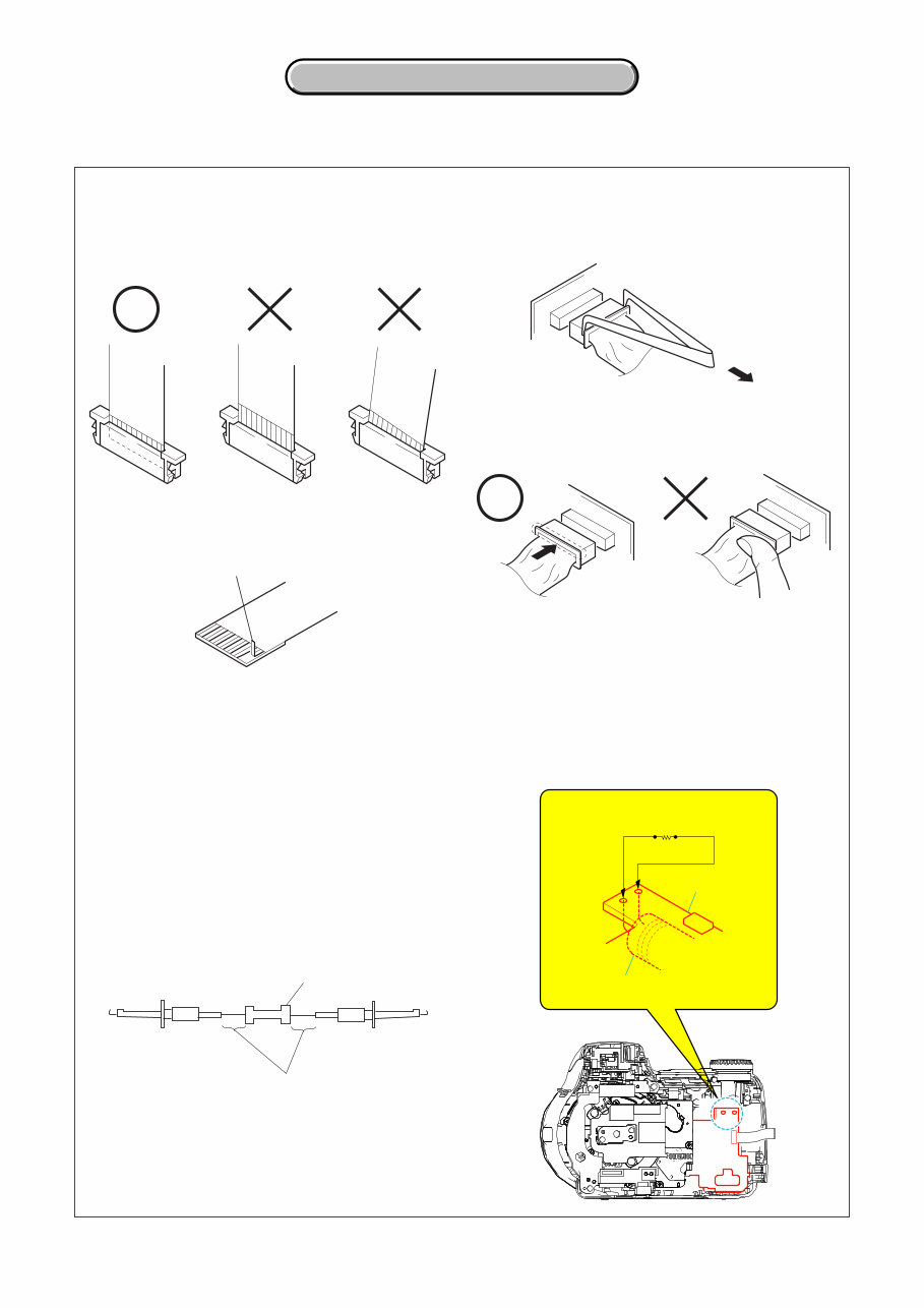
2-1 2. DISASSEMBLY 2. DISASSEMBLY DSC-H5_L2 2. DISASSEMBLY NOTE FOR REPAIR DISCHARGING OF THE FLASHLIGHT POWER SUPPLY CAPACITOR The charging elect capacitor 320uF (330V) is charged up to the maximum 300 V potential. There is a danger of electric shock by this high voltage when the capacitor is handled by hand. The electric shock is caused by the charged voltage which is kept without discharging when the main power of the DSC-H5 is simply turned off. Therefore, the remaining voltage must be discharged as described below. Preparing the Short Jig To preparing the short jig. a small clip is attached to each end of a resistor of 1 kW /1 W (1-215-869-11) Wrap insulating tape fully around the leads of the resistor to prevent electrical shock. 1 kΩ/1 W Wrap insulating tape. Make sure that the flat cable and flexible board are not cracked of bent at the terminal. Do not insert the cable insufficiently nor crookedly. Cut and remove the part of gilt which comes off at the point. (Take care that there are some pieces of gilt left inside) When remove a connector, don't pull at wire of connector. Be in danger of the snapping of a wire. When installing a connector, don't press down at wire of connector. Be in danger of the snapping of a wire. Discharging the Capacitor Short circuits between the positive and the negative terminals of charged capacitor with the short jig about 10 seconds. ST-142 Capacitor ST-142 board Short jig (1kΩ/1W)
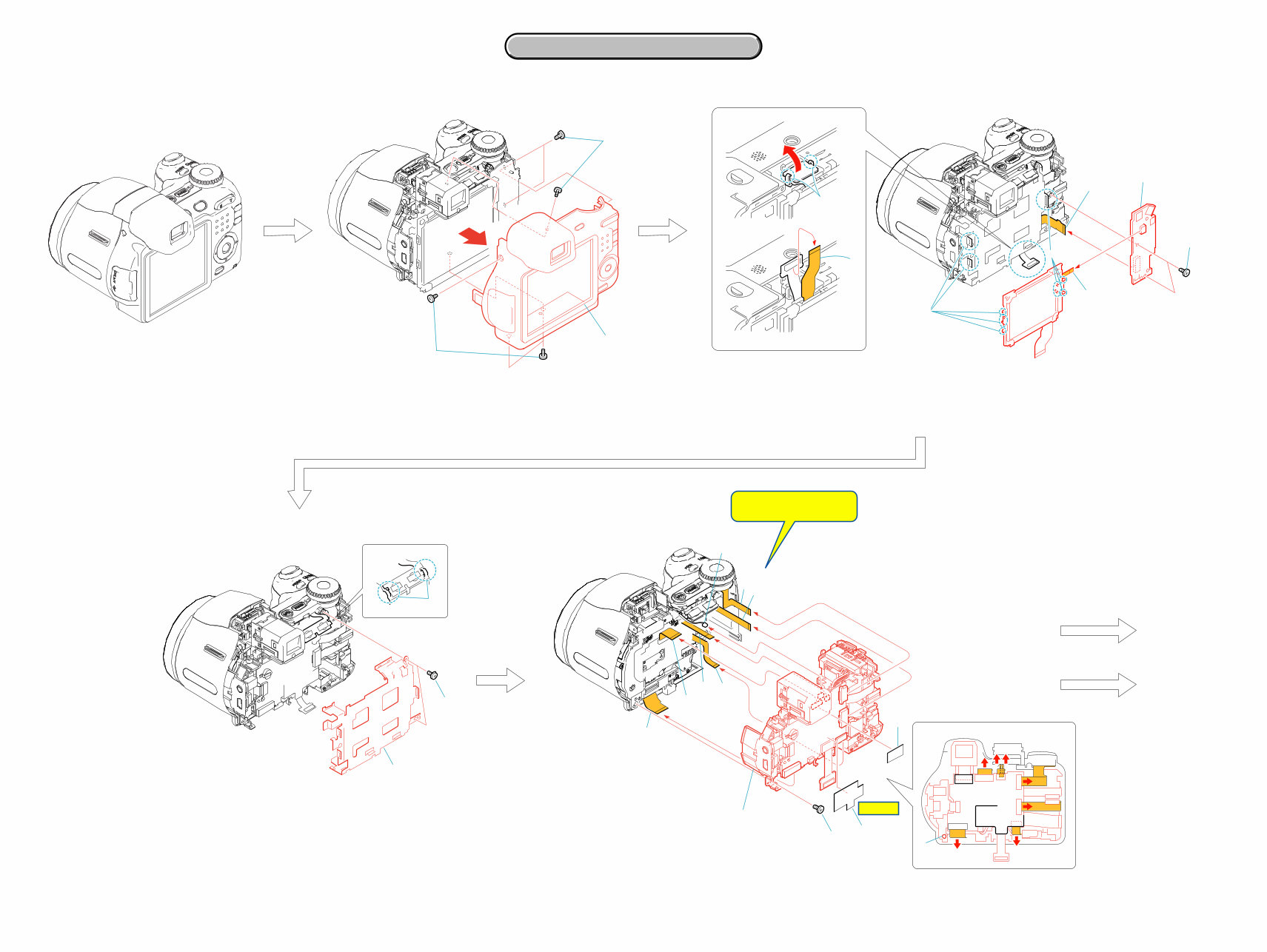
DSC-H5_L2 2-3 2-1. DISASSEMBLY The following flow chart shows the disassembly procedure. 2. DISASSEMBLY 2. DISASSEMBLY 2. DISASSEMBLY SY-150 SW- 471 SY-150 SY-150 SW- 471 6 6 1 Three screws (M1.7x4) 2 Three screws (M1.7x4) 3 Cabinet (rear) section 1 Two claws 2 Two tapping screws (M1.7x3.5) 3 LCD frame 2 3 1 2 3 qa 3 7 9 8 5 4 2 q; 1 1 Fuse replacement caution label 2 Flexible board (from the lens section) 3 Tape CD retainer (420) 4 CD-621 flexible board 5 AF-105 flexible board 6 Flexible board (from the lens section) 7 Control switch block 8 Flexible flat cable (ST-003) 9 From the microphone q; Tapping screw (M1.7x5) qa Main section 6 1 Note: Be very careful not to damage the flexible board. 5 3 4 7 9 8 6 2 1 q; B (See page 2-4) A (See page 2-4) HELP 01 1 Two claws 2 Flexible board (from the LCD unit) 3 Flexible board (from the light guide plate (3.0) block) 4 Two claws, two dowels 5 Claw, two dowels 6 Two tapping screws (M1.7x3.5) 7 SW-478 flexible board 8 SW-471 board 6 3 8 7 4 1 2 5
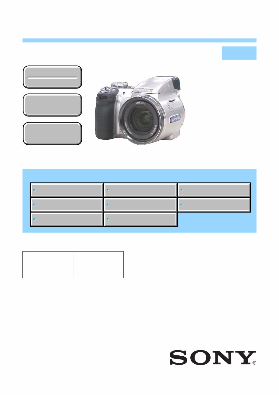
Do you own a Sony Cyber Shot DSC-H5 that requires maintenance or has encountered a malfunction? This official service repair manual is specifically designed for the Sony Cyber Shot DSC-H5, offering precise repair, maintenance, and troubleshooting solutions that can save you significant time and money.
While basic camera repairs are achievable by many, more complex issues may challenge even experienced users. That is why investing in this exceptional self-service and repair manual, tailored specifically for the Sony Cyber Shot DSC-H5, is a smart decision when facing critical troubleshooting problems.
This service manual provides comprehensive assistance in the following areas:
Disassembly
Repair
Maintenance
Circuit Diagrams
Block Diagrams
Frame Schematic Diagrams
Printed Wiring Boards
Repair Parts List
And others
Produced by the manufacturer, this factory service manual for the Sony Cyber Shot DSC-H5 offers the most accurate and detailed information available for your camera. It includes high-quality photos and clear, step-by-step instructions, making it an invaluable resource for those seeking to repair or maintain their camera. The manual is organized to allow quick access to the critical information you need for a successful repair process.
Manual Details:
Format: PDF
Pages: 51
Language: English
Compatible: Windows/Mac
Printable Pages: Yes
If you require Adobe Reader to access the PDF file, please download it for free from the following link: http://get.adobe.com/reader
Purchase with confidence knowing that this manual is dedicated to your Sony Cyber Shot DSC-H5. Please feel free to contact us with any questions. Thank you.