MVC-FD95 AEP Model UK Model SERVICE MANUAL DIGITAL STILL CAMERA Level 1 SPECIFICATIONS System Image device 1/2.7 type color CCD Lens 10× zoom lens f = 6.0 – 60.0 mm (1/4 – 2 3/8 inches) (39 – 390 mm (1 9/16 – 15 3/8 in) when converted into a 35 mm still camera) F = 2.8 Exposure control Automatic exposure White balance Automatic, Indoor, Outdoor, One-push Data compression system Movie: MPEG1 Still: Floppy disk: JPEG (JFIF) “Memory Stick”: JPEG (Exif2.1) GIF (in TEXT mode) Audio (with still image): MPEG AUDIO (Monaural) Recording medium Floppy disk: 3.5 inch 2HD MS-DOS format (1.44MB) MSAC-FD2M Floppy Disk Adaptor for Memory Stick: DCF98 format Flash Recommended recording distance: 0.6 m to 2.5 m (23 5/8 in to 8 1/3 feet) Input and Output connector AUDIO (MONO) /VIDEO OUT (Monaural) Minijack Video: 1 Vp-p, 75 Ω, unbalanced, sync negative Audio: 327 mV (at a 47 kΩ load) Output impedance: 2.2 kΩ External flash jack Minijack LCD screen Used LCD panel TFT (Thin Film Transistor active matrix) drive Total number of dots 123,200 (560×220) dots Finder Used LCD panel TFT (Thin Film Transistor active matrix) drive Total number of dots 180,000 (800×225) dots General Application Sony battery pack NP-F330 (supplied)/F550 Power requirements 8.4 V Power consumption (During shooting) 3.9 W (When using the LCD screen) 3.5 W (When using the finder) Operation temperature 0°C to 40°C (32°F to 104°F) Storage temperature –20°C to +60°C (–4°F to +140°F) Maximum dimensions 126×124×184 mm (5×5× 7 1/4 in) (w/h/d) Mass Approx. 970 g (2 lb 2 oz) (including battery, floppy disk and lens cap, etc.) Built-in microphone Electret condenser microphone Built-in speaker Dynamic speaker AC-L10A/L10B/L10C AC power adaptor Power requirements 100 V to 240 V AC, 50/ 60 Hz Rated output voltage DC 8.4 V, 1.5 A in operating mode Operation temperature 0°C to 40°C (32°F to 104°F) Storage temperature –20°C to +60°C (–4°F to +140°F) Maximum dimensions 125×39×62 mm (5×1 9/16× 2 1/2 inches) (w/h/d) Mass Approx. 280 g (10 oz) NP-F330 battery pack Used battery Lithium ion battery Maximum voltage DC 8.4 V Nominal voltage DC 7.2 V Capacity 5.0 Wh (700 mAh) Accessories AC-L10A/L10B/L10C AC power adaptor (1) Power cord (mains lead) (1) NP-F330 battery pack (1) A/V connecting cable (1) Shoulder strap (1) Lens cap (1) Lens cap strap (1) CD-ROM (1) Operating instructions (1) Design and specifications are subject to change without notice. Ver 1.0 2000. 04
— 2 — SAFETY-RELATED COMPONENT WARNING!! COMPONENTS IDENTIFIED BY MARK 0 OR DOTTED LINE WITH MARK 0 ON THE SCHEMATIC DIAGRAMS AND IN THE PARTS LIST ARE CRITICAL TO SAFE OPERATION. REPLACE THESE COMPONENTS WITH SONY PARTS WHOSE PART NUMBERS APPEAR AS SHOWN IN THIS MANUAL OR IN SUPPLEMENTS PUBLISHED BY SONY. 1. Check the area of your repair for unsoldered or poorly-soldered connections. Check the entire board surface for solder splashes and bridges. 2. Check the interboard wiring to ensure that no wires are "pinched" or contact high-wattage resistors. 3. Look for unauthorized replacement parts, particularly transistors, that were installed during a previous repair. Point them out to the customer and recommend their replacement. 4. Look for parts which, through functioning, show obvious signs of deterioration. Point them out to the customer and recommend their replacement. 5. Check the B+ voltage to see it is at the values specified. 6. Flexible Circuit Board Repairing • Keep the temperature of the soldering iron around 270˚C during repairing. • Do not touch the soldering iron on the same conductor of the circuit board (within 3 times). • Be careful not to apply force on the conductor when soldering or unsoldering. SAFETY CHECK-OUT After correcting the original service problem, perform the following safety checks before releasing the set to the customer. TABLE OF CONTENTS SERVICE NOTE ····································································· 3 1. MAIN PARTS 1. ORNAMENTAL PARTS···················································· 5 2. DISASSEMBLY································································· 6 2-1. CABINET (TOP) ASSEMBLY, MA-379 BOARD············ 6 2-2. VF-143 BOARD, VF LENS ASSEMBLY ························· 7 2-3. LCD, PK-49 BOARD ························································· 8 2-4. FC-72, FU-139 BOARDS, FLOPPY DISK DRIVE ·········· 9 2-5. LENS COMPLETE ASSEMBLY ···································· 10 2-6. VP-50 BOARD, LENS BLOCK ASSEMBLY ················ 11 2-7. EJECT BUTTON SECTION ··········································· 12 2-8. AE-022 BOARD ······························································ 13 2-9. FLASH UNIT, MICROPHONE UNIT ···························· 13 2. REPAIR PARTS LIST 2-1. EXPLODED VIEWS ······················································· 14 2-1-1.OVERALL ASSEMBLY SECTION ································ 14 2-1-2.TOP CABINET ASSEMBLY SECTION ························· 15 2-1-3.EVF BLOCK ASSEMBLY SECTION ···························· 16 2-1-4.CABINET (FRONT) BLOCK ASSEMBLY SECTION ·· 17 2-1-5.LENS COMPLETE ASSEMBLY SECTION ·················· 18 2-1-6.CABINET (REAR) BLOCK ASSEMBLY SECTION ···· 19 3. GENERAL Getting started Identifying the parts ································································ 20 Preparing the power supply ···················································· 20 Setting the date and time ························································· 21 Inserting a floppy disk ···························································· 22 Basic operations B Recording Recording still images ···························································· 22 Recording moving images ······················································ 23 B Playback Playing back still images ························································ 24 Playing back moving images ·················································· 24 Viewing images using a personal computer ··························· 24 Image file storage destinations and image file names ············ 25 Advanced operations Before performing advanced operations How to use the PLAY/STILL/MOVIE selector······················ 25 How to use the control button ················································· 25 How to change the menu settings ··········································· 26 B Various recording Setting the image size (IMAGE SIZE) ··································· 27 Recording still images for e-mail (E-MAIL) ·························· 27 Adding audio files to still images (VOICE) ··························· 27 Recording text documents (TEXT) ········································ 28 Recording images in macro ···················································· 28 Focusing manually ·································································· 28 Using the PROGRAM AE function ········································ 28 Using the Spot light – metering function ································ 28 Adjusting the exposure (EXPOSURE) ··································· 28 Adjusting the white balance (WHITE BALANCE) ··············· 29 Recording the date and time on the still image (DATE/TIME) · 29 Enjoying picture effects (PICTURE EFFECT) ······················ 29 B Various playback Playing back six images at once (INDEX) ····························· 29 Enlarging a part of the still image (Zoom and trimming) ······· 29 Playing back the still images in order (SLIDE SHOW) ········· 30 Viewing images on a TV screen ············································· 30 B Editing Preventing accidental erasure (PROTECT) ···························· 30 Deleting images (DELETE) ··················································· 30 Changing the recorded still image size (RESIZE) ·················· 31 Copying images (COPY) ························································ 31 Copying all the information on your floppy disk (DISK COPY) ·· 31 Selecting still images to print (PRINT MARK) ····················· 31 Format ····················································································· 32 Additional information Precautions ·············································································· 32 Using your camera abroad ······················································ 32 Troubleshooting ······································································ 33 Warning and notice messages ················································· 33 Self-diagnosis display ····························································· 34 LCD screen/finder indicators ·················································· 34
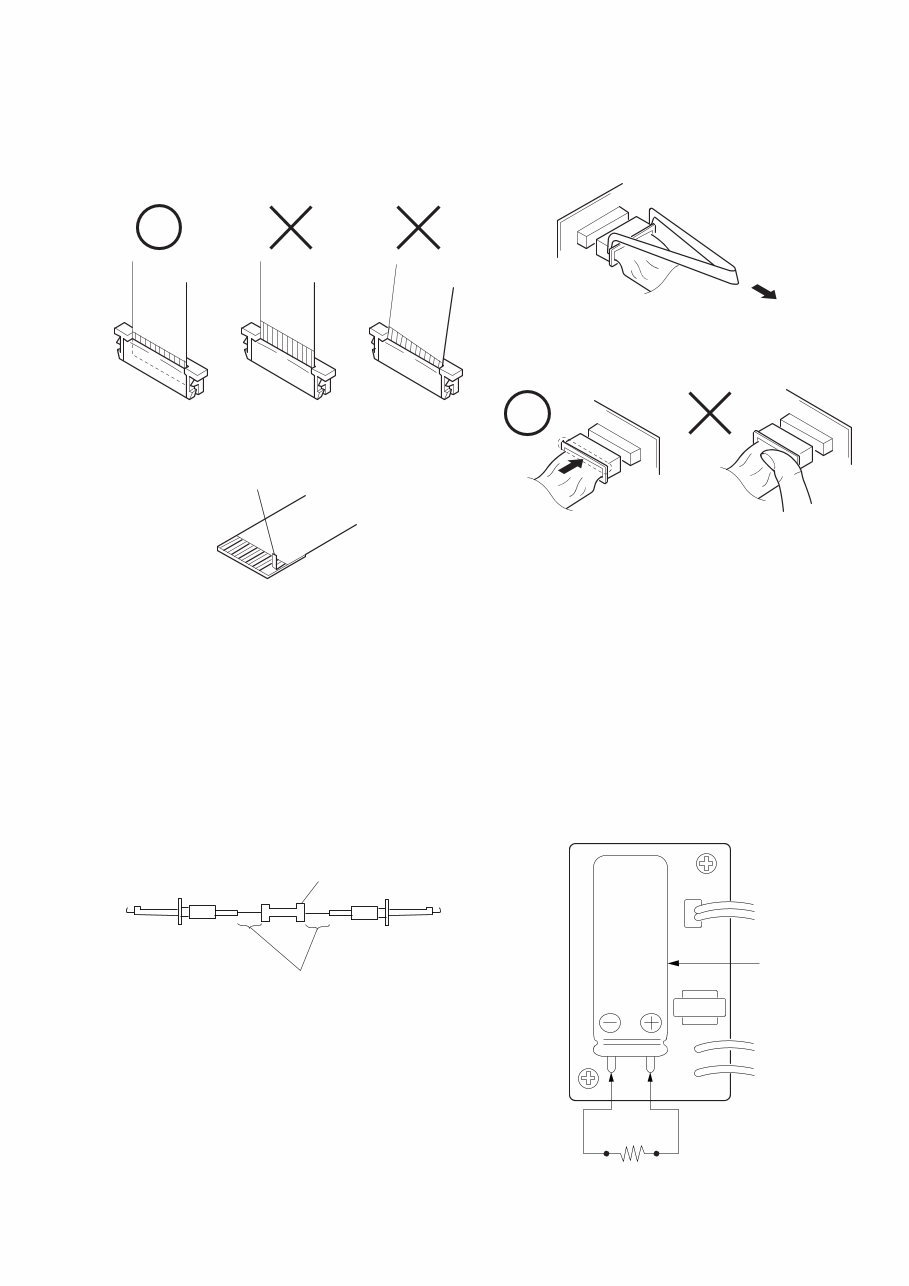
— 3 — SERVICE NOTE • NOT FOR REPAIR [Discharging of the FLASH unit’s charging capacitor] The charging capacitor of the FLASH unit is charged up to the maximum 300 V potential. There is a danger of electric shock by this high voltage when the capacitor is handled by hand. The electric shock is caused by the charged voltage which is kept without discharging when the main power of the MVC-FD95 is simply turned off. Therefore, the remaining voltage must be discharged as described below. Preparing the Short Jig To preparing the short jig. a small clip is attached to each end of a resistor of 1 kΩ /1 W (1-215-869-11) Wrap insulating tape fully around the leads of the resistor to prevent electrical shock. 1 kΩ/1 W Wrap insulating tape. Make sure that the flat cable and flexible board are not cracked of bent at the terminal. Do not insert the cable insufficiently nor crookedly. Cut and remove the part of gilt which comes off at the point. (Take care that there are some pieces of gilt left inside) When remove a connector, don't pull at wire of connector. Be in danger of the snapping of a wire. When installing a connector, don't press down at wire of connector. Be in danger of the snapping of a wire. Discharging the Capacitor Short circuits between the positive and the negative terminals of charged capacitor with the short jig about 10 seconds. Capacitor Short jig
— 4 — Display Code C:32:01 C:13:01 E:91:01 E:61:00 E:61:10 Countermeasure Change the disk and turn off the main power then back on. Replace the floppy disk. Format the floppy disk with the MVC- FD95. Checking of flash unit or replacement of flash unit Checking of lens drive circuit Cause Defective floppy disk. • The type of floppy disk that cannot be used by this machine, is inserted. (Such as 2DD) • Data is damaged. • Unformatted disk is inserted. Abnormality when flash is being charged. When failed in the focus initialization. Caution Display During Error DRIVE ERROR DISK ERROR Flash LED Flash display Flashing at 3.2 Hz — Self-diagnosis display • C: ss: ss The contents which can be handled by customer, are displayed. • E: ss: ss The contents which can be handled by engineer, are displayed. [Description on Self-diagnosis Display]
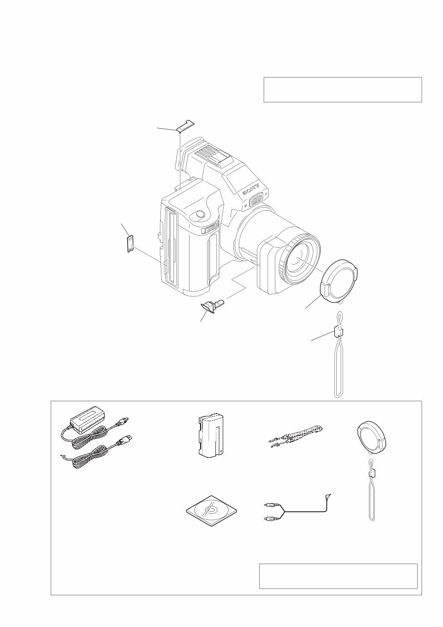
MVC-FD95 1. MAIN PARTS — 5 — Note: • Follow the disassembly procedure in the numerical order given. • Items marked “*” are not stocked since they are seldom required for routine service. Some delay should be anticipated when ordering these items. • The parts numbers of such as a cabinet are also appeared in this section. Refer to the parts number mentioned below the name of parts to order. 1. ORNAMENTAL PARTS Note : The components identified by mark 0 or dotted line with mark 0 are critical for safety. Replace only with part number specified. Checking supplied accessories Note : The components identified by mark 0 or dotted line with mark 0 are critical for safety. Replace only with part number specified. Other accessories (Fig. A) (Fig. B) AC-VF10 power adaptor (1) 0 1-475-599-11 Power cord set (1) (AEP model) 0 1-769-608-11 Power cord (with filter) (1) (UK model) 0 1-783-374-11 NP-F330 battery pack (1) A-7094-141-A Shoulder belt (S) (1) 3-987-015-01 (Fig. A) Lens cap assy (1) X-3950-691-1 (Fig. B) Cap string (1) 3-062-043-01 Cord connector (A/V) (1) 1-783-738-11 3-061-389-11 MANUAL, INSTRUCTION (ENGLISH) 3-061-389-21 MANUAL, INSTRUCTION (FRENCH/GERMAN)(AEP MODEL) 3-061-389-31 MANUAL, INSTRUCTION (SPANISH/PORTUGUESE)(AEP MODEL) 3-061-389-41 MANUAL, INSTRUCTION (ITALIAN/DUTCH)(AEP MODEL) 3-061-389-61 MANUAL, INSTRUCTION (SWEDISH/RUSSIAN)(AEP MODEL) CPC Lid 3-058-792-11 ACC jack cover 3-060-928-01 Lens cap assembly X-3950-691-1 Cap string 3-062-043-01 DC in cover 3-060-893-01 Bundle soft (2000) (1) 3-060-716-01
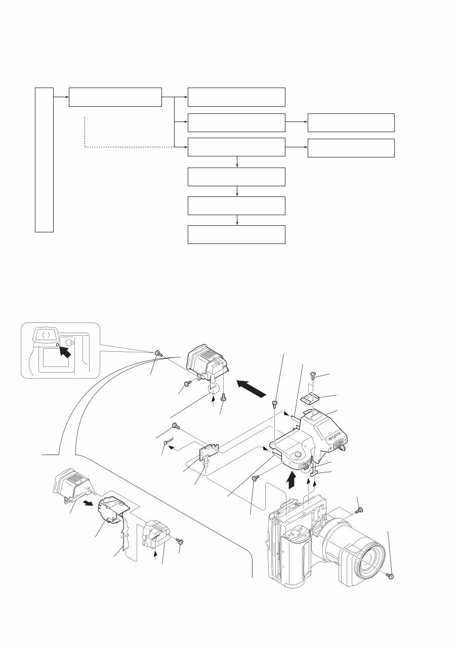
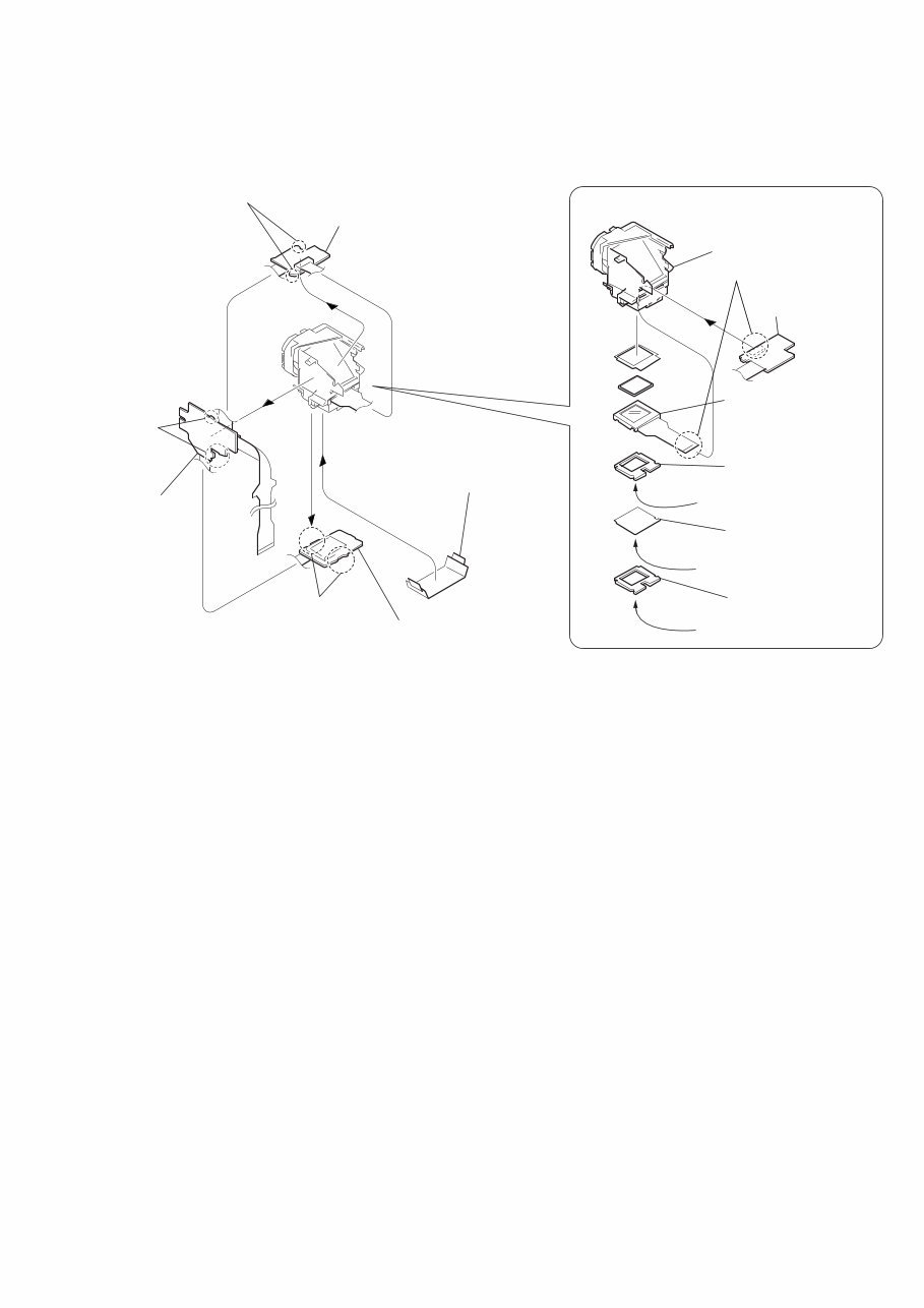
— 7 — 2-2. VF-143 BOARD, VF LENS ASSEMBLY 3 Cover the cushion and diffusion plate with a piece of paper or adhesive tape or the like so that the parts must not be scattered. 6 Two claws 4 Three claws 1 Four claws 2 VF-143 board (1) (VF-143 board) 5 VF-143 board (2) 7 VF-143 board (3) VF lens assembly 4 LCD cushion (1) (97) 3 BL illuminator (97) 2 LCD cushion (2) (97) 5 LCD (LCX033AK-J) 1 LCD (LCX033AK-J)(16P) Shining surface Rough surface Shining surface REMOVING THE VF LENS ASSEMBLY
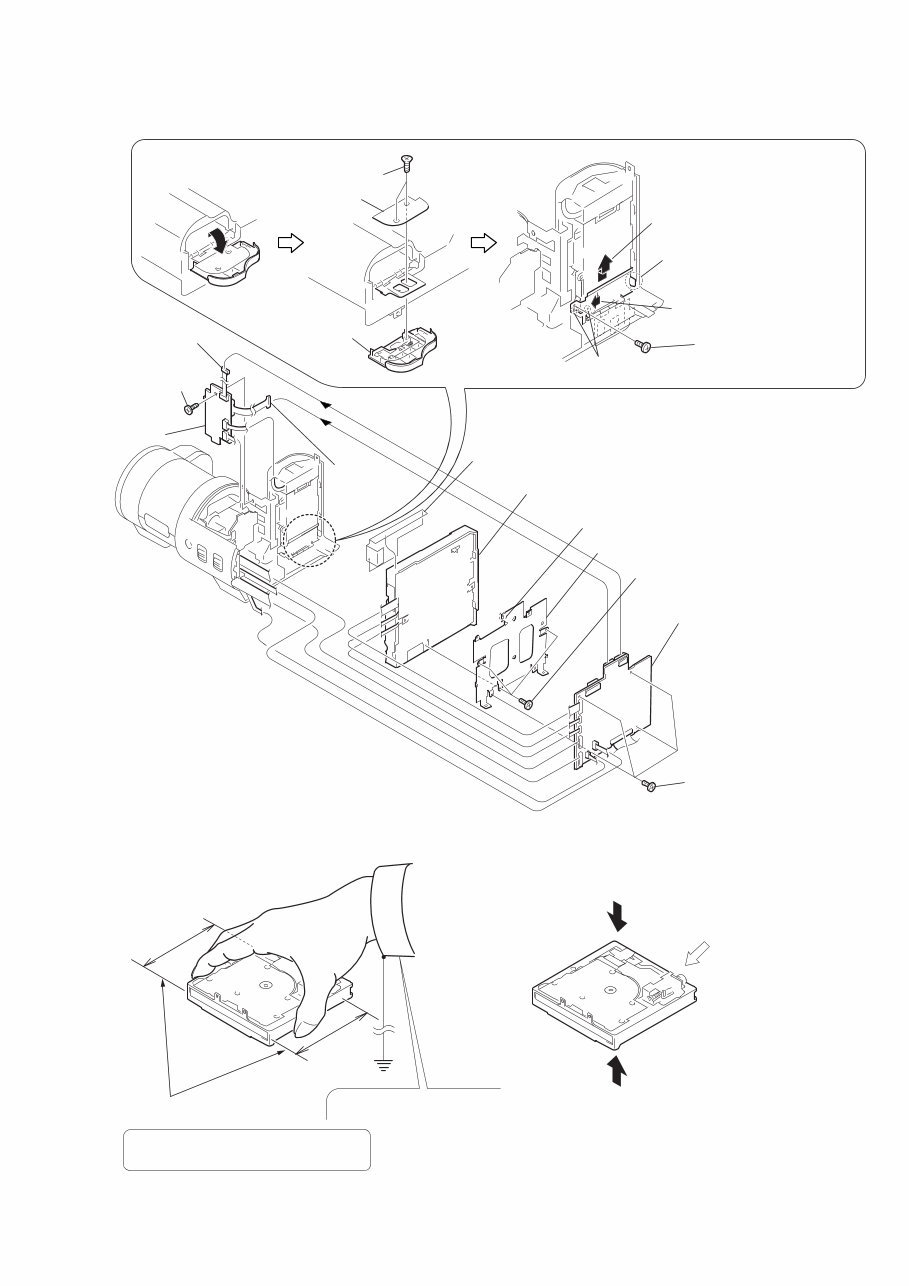
— 9 — 2-4. FC-72, FU-139 BOARDS, FLOPPY DISK DRIVE A 2 Two tapping screws (M2 × 4) 4 Battery lid 8 Claw 6 Two claws B 3 Hinge retainer 7 Remove the hinge assembly in the direction of the arrow A. 9 Remove the hinge assembly in the direction of the arrow B. 1 5 Tapping screw (M2 × 5) REMOVING THE HINGE ASSEMBLY Board FC-72 2 FC-72 board 7 FC Bracket 6 Claw 9 Floppy disk drive 8 Sheet (B) 4 Harness (FU-53)(12p) 3 Harness (FU-54)(5p) qa FU-139 board 1 Four screws (M2 × 2.5) 5 Three screws (M2 × 2.5) q; Screw (M2 × 3), lock ace, p2 Range of holding FDD Wear an earthed wrist strap. Do not hold an FDD by sandwiching the upper and lower surfaces. Do not apply any physical stress to the center of the top plate. If the FDD is not held correctly, the components of the FDD may be bent. Do not apply any physical stress to the spindle motor. 2. Prohibited Items Cautions When Handling FDD 1. Correct Way of Holding an FDD
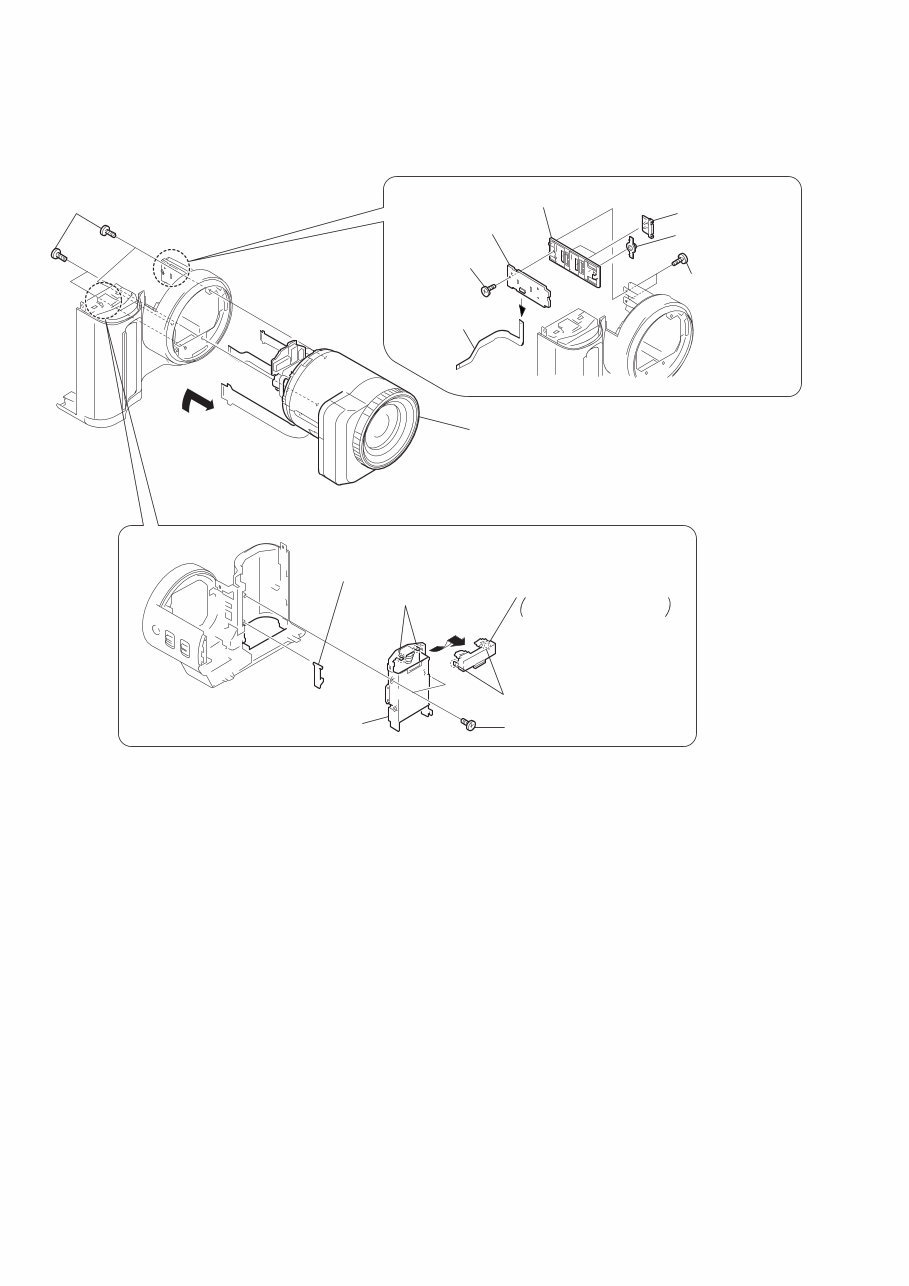
— 10 — 2-5. LENS COMPLETE ASSEMBLY B 4 Two claws 2 Battery holder 3 BT lock claw 6 Battery terminal board Remove it in the direction of the arrow B. 5 Two claws 1 Two tapping screws (M2 × 5) REMOVING THE CF-074 BOARD REMOVING THE BATTERY TERMINAL BOARD 3 CF-074 board 7 SS holder 5 Two SS knobs 6 Macro button 1 FP-172 flexible board (6p) 2 Tapping screw (M2 × 5) 4 Two tapping screws (M1.7 × 3.5) 2 Lens complete assembly (Remove it in the direction of the arrow A.) A 1 Four screws (M2 × 3), lock ace p2
Get the repair manual for the Sony MVC FD95 STILL CAMERA. This manual contains easy step-by-step information and illustrations to guide you through the repair process. Whether you're a professional mechanic or a DIY enthusiast, you can effortlessly complete simple to complicated repairs with the provided information. The easy-to-read and use format allows you to print or view any sections with ease.
Service Note
Main Parts
Repair Parts List
General
Plus more...
Total Pages: 34
Format: PDF
Language: English
Compatible: Win/Mac
Save money by doing repairs on your own! These manuals provide very easy-to-follow, step-by-step instructions suitable for any skill level. Tons of pictures and diagrams are included in the manual to better understand the instructions. All pages are printable, so you can run off what you need and take it with you.
Instant access means no shipping cost or waiting for the CD to arrive in the mail. Get it now!