2 TABLE OF CONTENTS PAGE PAGE 1 Safety Precautions ----------------------------------------------- 3 1.1. General Guidelines ----------------------------------------3 1.2. Leakage Current Cold Check ---------------------------3 1.3. Leakage Current Hot Check (See Figure 1)---------3 1.4. How to Discharge the Capacitor on Capacitor P.C.B.----------------------------------------------------------4 2 Warning -------------------------------------------------------------- 5 2.1. Prevention of Electrostatic Discharge (ESD) to Electrostatically Sensitive (ES) Devices ----------5 2.2. How to Recycle the Lithium Ion Battery (U.S. Only)-----------------------------------------------------------5 2.3. How to Replace the Lithium Battery -------------------6 3 Service Navigation------------------------------------------------ 7 3.1. Introduction --------------------------------------------------7 3.2. Important Notice --------------------------------------------7 3.3. Service Notes -----------------------------------------------9 3.4. General Description About Lead Free Solder (PbF) -------------------------------------------------------- 10 3.5. How to Define the Model Suffix (NTSC or PAL model)------------------------------------------------------- 11 4 Specifications ---------------------------------------------------- 16 5 Location of Controls and Components ------------------ 18 6 Service Mode ----------------------------------------------------- 19 6.1. Error Code Memory Function ------------------------- 19 7 Troubleshooting Guide---------------------------------------- 22 7.1. Wi-Fi Module (Wi-Fi P.C.B. Unit) --------------------- 22 8 Service Fixture & Tools --------------------------------------- 23 8.1. Service Fixture and Tools ------------------------------ 23 8.2. When Replacing the Main P.C.B. --------------------23 8.3. Service Position ------------------------------------------ 24 9 Disassembly and Assembly Instructions --------------- 25 9.1. Disassembly Flow Chart-------------------------------- 25 9.2. P.C.B. Location -------------------------------------------25 9.3. Disassembly Procedure -------------------------------- 26 9.4. Lens Disassembly Procedure------------------------- 34 9.5. Assembly Procedure for Lens ------------------------ 39 9.6. Removal of the MOS Unit------------------------------ 46 10 Measurements and Adjustments -------------------------- 47 10.1. Introduction ------------------------------------------------ 47 10.2. Before Disassembling the unit ------------------------ 47 10.3. Details of Electrical Adjustment----------------------- 49 10.4. After Adjustment------------------------------------------ 55 11 Maintenance ------------------------------------------------------ 56 11.1. Cleaning Lens, Viewfinder and LCD Panel-------- 56 12 Block Diagram --------------------------------------------------- 57 12.1. Overall Block Diagram ---------------------------------- 57 12.2. System Control Block Diagram ----------------------- 58 12.3. Audio/Video Process/ HDMI Block Diagram ------ 59 12.4. Lens/Flash Block Diagram ----------------------------- 60 12.5. Power (1) Block Diagram------------------------------- 61 12.6. Power (2) Block Diagram------------------------------- 62 13 Wiring Connection Diagram -------------------------------- 63 13.1. Interconnection Schematic Diagram---------------- 63 14 Schematic Diagram -------------------------------------------- 65 15 Printed Circuit Board------------------------------------------ 65 16 Exploded View and Replacement Parts List ----------- 65
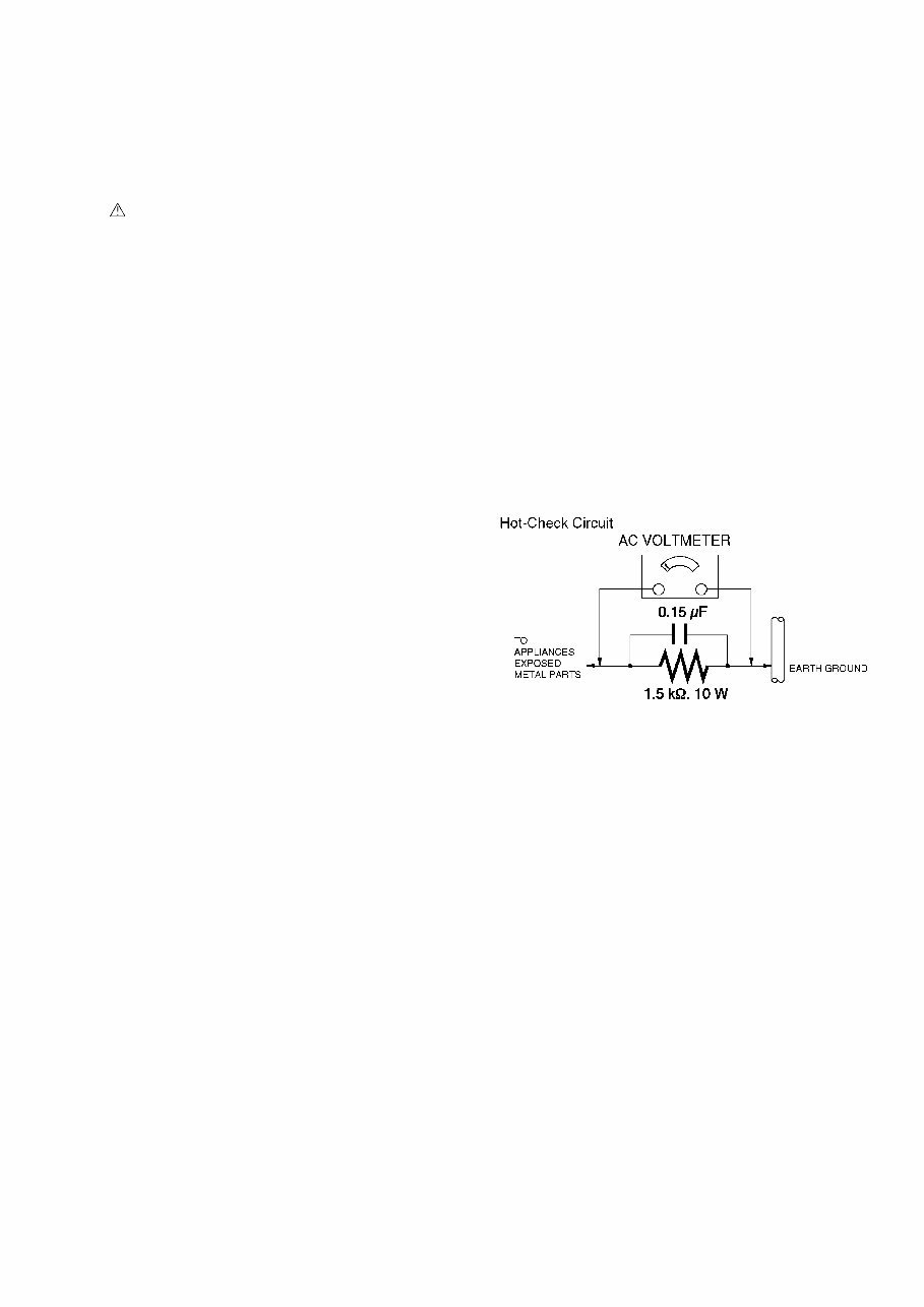
3 1 Safety Precautions 1.1. General Guidelines 1. IMPORTANT SAFETY NOTICE There are special components used in this equipment which are important for safety. These parts are marked by in the Schematic Diagrams, Circuit Board Layout, Exploded Views and Replacement Parts List. It is essential that these critical parts should be replaced with manufacturer's specified parts to prevent X-RADIATION, shock fire, or other hazards. Do not modify the original design without permission of manufacturer. 2. An Isolation Transformer should always be used during the servicing of AC Adaptor whose chassis is not isolated from the AC power line. Use a transformer of adequate power rating as this protects the technician from accidents resulting in personal injury from electrical shocks. It will also protect AC Adaptor from being damaged by accidental shorting that may occur during servicing. 3. When servicing, observe the original lead dress. It a short circuit is found, replace all parts which have been overheated or damaged by the short circuit. 4. After servicing, see to it that all the protective devices such as insulation barriers, insulation papers shields are properly installed. 5. After servicing, make the following leakage current checks to prevent the customer from being exposed to shock hazards. 1.2. Leakage Current Cold Check 1. Unplug the AC cord and connect a jumper between the two prongs on the plug. 2. Measure the resistance value, with an ohmmeter, between the jumpered AC plug and each exposed metallic cabinet part on the equipment such as screwheads, connectors, control shafts, etc. When the exposed metallic part has a return path to the chassis, the reading should be between 1M and 5.2M. When the exposed metal does not have a return path to the chassis, the reading must be infinity. 1.3. Leakage Current Hot Check (See Figure 1) 1. Plug the AC cord directly into the AC outlet. Do not use an isolation transformer for this check. 2. Connect a 1.5k, 10 W resistor, in parallel with a 0.15F capacitor, between each exposed metallic part on the set and a good earth ground, as shown in Figure 1. 3. Use an AC voltmeter, with 1 k/V or more sensitivity, to measure the potential across the resistor. 4. Check each exposed metallic part, and measure the voltage at each point. 5. Reverse the AC plug in the AC outlet and repeat each of the above measurements. 6. The potential at any point should not exceed 0.75 V RMS. A leakage current tester (Simpson Model 229 or equivalent) may be used to make the hot checks, leakage current must not exceed 1/2 mA. In case a measurement is outside of the limits specified, there is a possibility of a shock hazard, and the equipment should be repaired and rechecked before it is returned to the customer. Figure 1
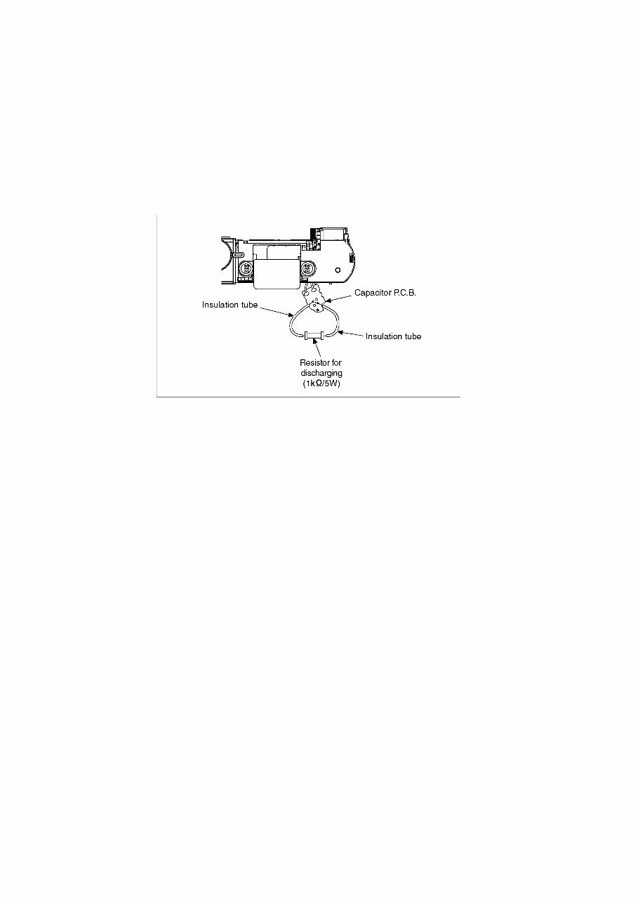
4 1.4. How to Discharge the Capacitor on Capacitor P.C.B. CAUTION: 1. Be sure to discharge the capacitor on Capacitor P.C.B.. 2. Be careful of the high voltage circuit on Capacitor P.C.B. when servicing. [Discharging Procedure] 1. Refer to the disassemble procedure and remove the necessary parts/unit. 2. Install the insulation tube onto the lead part of Resistor (ERG5SJ102:1k /5W). (an equivalent type of resistor may be used.) 3. Place a resistor between both terminals of capacitor on the Capacitor P.C.B. for approx. 5 seconds. 4. After discharging, confirm that the capacitor voltage is lower than 10V using a voltmeter. Fig. F1
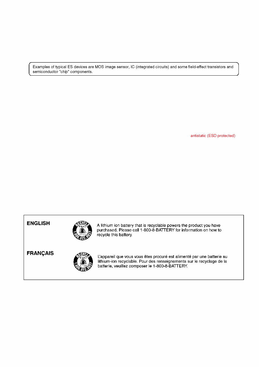
5 2 Warning 2.1. Prevention of Electrostatic Discharge (ESD) to Electrostatically Sensitive (ES) Devices Some semiconductor (solid state) devices can be damaged easily by static electricity. Such components commonly are called Electrostatically Sensitive (ES) Devices. The following techniques should be used to help reduce the incidence of component damage caused by electrostatic discharge (ESD). 1. Immediately before handling any semiconductor component or semiconductor-equipped assembly, drain off any ESD on your body by touching a known earth ground. Alternatively, obtain and wear a commercially available discharging ESD wrist strap, which should be removed for potential shock reasons prior to applying power to the unit under test. 2. After removing an electrical assembly equipped with ES devices, place the assembly on a conductive surface such as aluminum foil, to prevent electrostatic charge buildup or exposure of the assembly. 3. Use only a grounded-tip soldering iron to solder or unsolder ES devices. 4. Use only an antistatic solder removal device. Some solder removal devices not classified as can generate electrical charge sufficient to damage ES devices. 5. Do not use freon-propelled chemicals. These can generate electrical charges sufficient to damage ES devices. 6. Do not remove a replacement ES device from its protective package until immediately before you are ready to install it. (Most replacement ES devices are packaged with leads electrically shorted together by conductive foam, aluminum foil or comparable conductive material). 7. Immediately before removing the protective material from the leads of a replacement ES device, touch the protective material to the chassis or circuit assembly into which the device will be installed. CAUTION: Be sure no power is applied to the chassis or circuit, and observe all other safety precautions. 8. Minimize bodily motions when handling unpackaged replacement ES devices. (Otherwise harmless motion such as the brushing together of your clothes fabric or the lifting of your foot from a carpeted floor can generate static electricity (ESD) sufficient to damage an ES device). 2.2. How to Recycle the Lithium Ion Battery (U.S. Only)
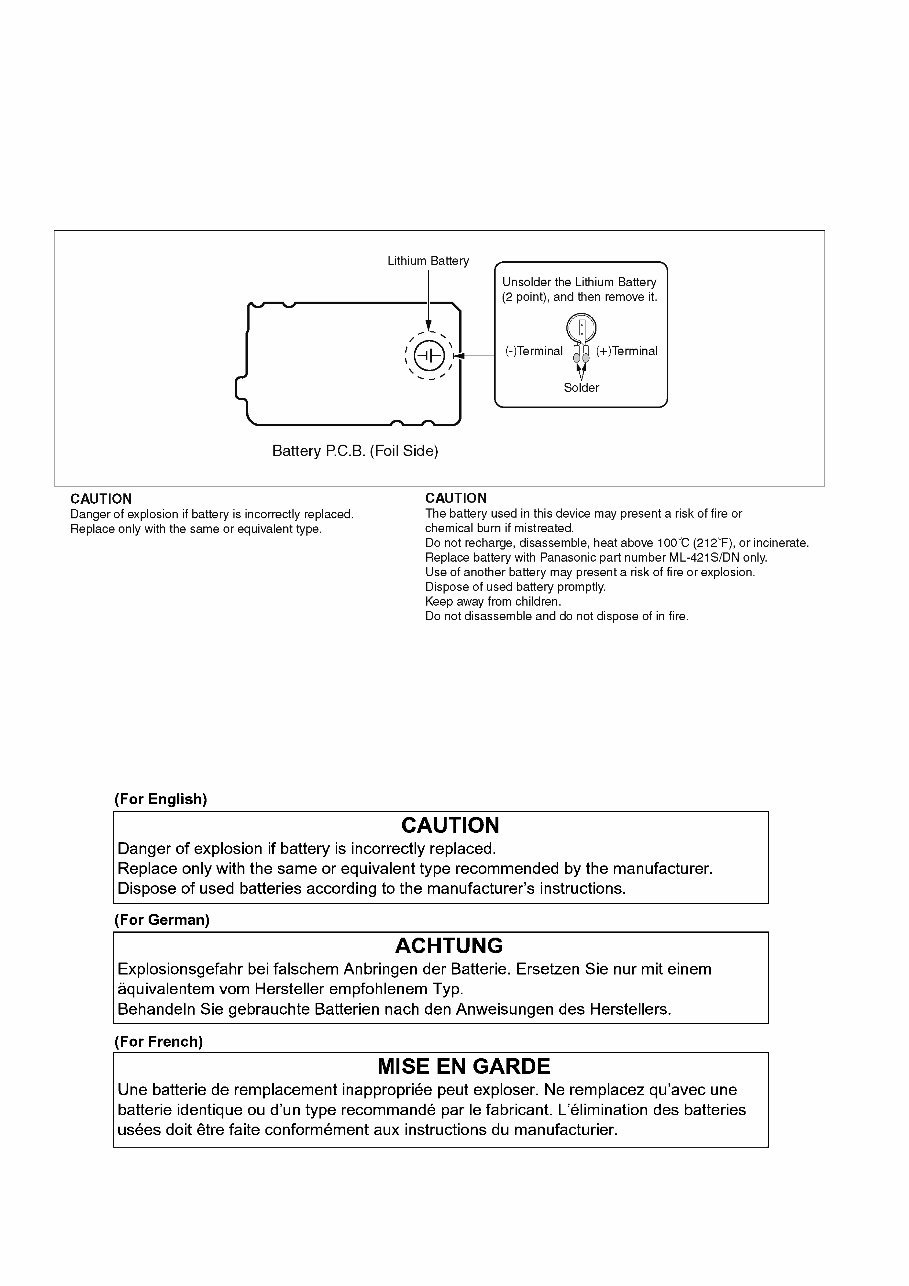
6 2.3. How to Replace the Lithium Battery 2.3.1. Replacement Procedure 1. Remove the Battery P.C.B. (Refer to Disassembly Procedures.) 2. Unsolder the each soldering point of electric lead terminal for Lithium battery (Ref. No. B9401 at foil side of Battery P.C.B.) and remove the Lithium battery together with electric lead terminal. Then replace it into new one. Note: The Lithium battery includes electric lead terminals. Note: The lithium battery is a critical component. It must never be subjected to excessive heat or discharge. It must therefore only be fitted in equipment designed specifically for its use. Replacement batteries must be of the same type and manufacture. They must be fitted in the same manner and location as the original battery, with the correct polarity contacts observed. Do not attempt to re-charge the old battery or re-use it for any other purpose. It should be disposed of in waste products destined for burial rather than incineration. Note: Above caution is applicable for a battery pack which is for DMC-TZ100/TZ101/TZ110/ZS100/ZS110 series, as well.
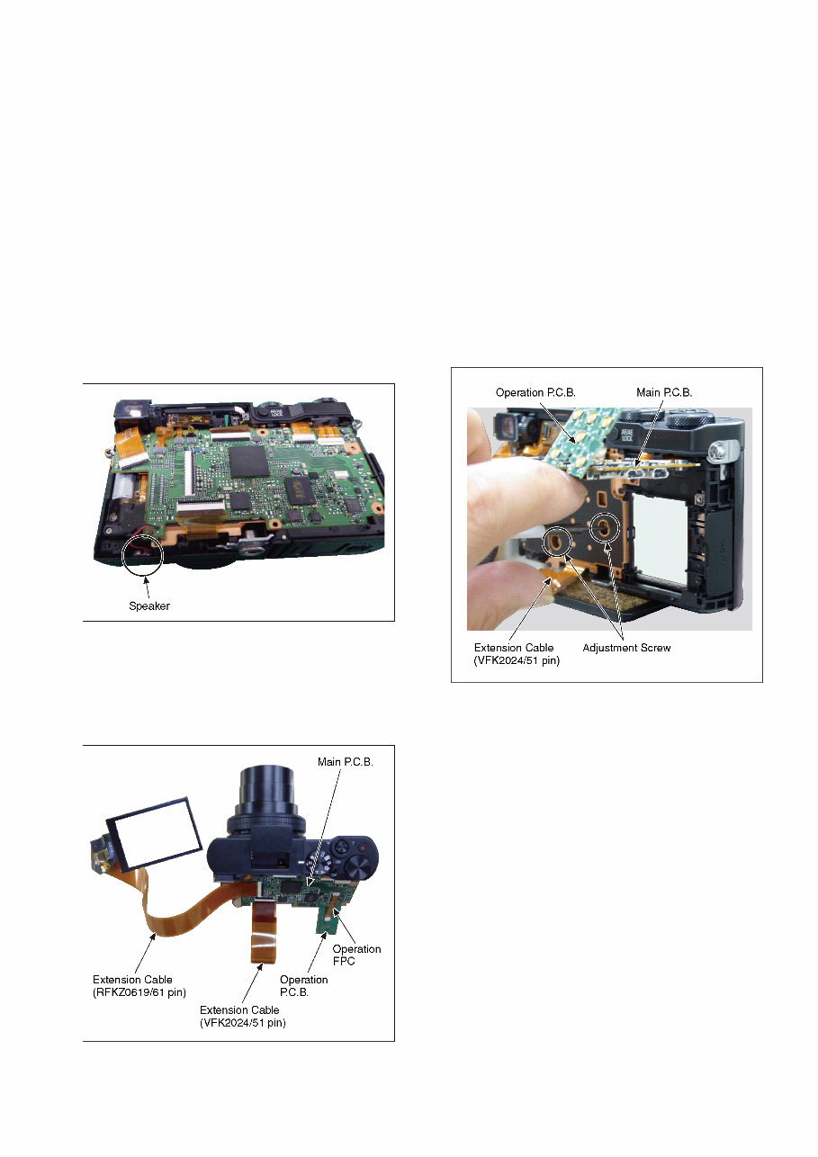
7 3 Service Navigation 3.1. Introduction This service manual contains technical information, which will allow service personnel's to understand and service this model. Please place orders using the parts list and not the drawing reference numbers. If the circuit is changed or modified, the information will be followed by service manual to be controlled with original service manual. 3.2. Important Notice 3.2.1. About lens block The image sensor (MOS) unit which are connected to the lens unit with 3 screws. 2 of these 3 screws are locked, after performing the Optical tilt adjustment. During servicing, if one of MOS fixing screws are loosened, the Optical tilt adjustment must be performed. (About the Optical tilt adjustment, refer to the "10.3.2 Adjustment Specifications" for details.) • Using the Extension cable, perform the Optical tilt adjustment according to the following procedure. 1. Remove the Frame Plate Unit. (Refer to Disassembly Procedures.) 2. Remove the Speaker from the Frame Unit. 3. Using the Operation FPC, connect the Main P.C.B. to Operation P.C.B.. 4. Using the Extension cable, connect the Main P.C.B. to LCD Unit. 5. Using the Extension cable, connect the Main P.C.B. to Lens Unit Flex. 6. The Main P.C.B. is lifted, perform the Optical tilt adjustment.
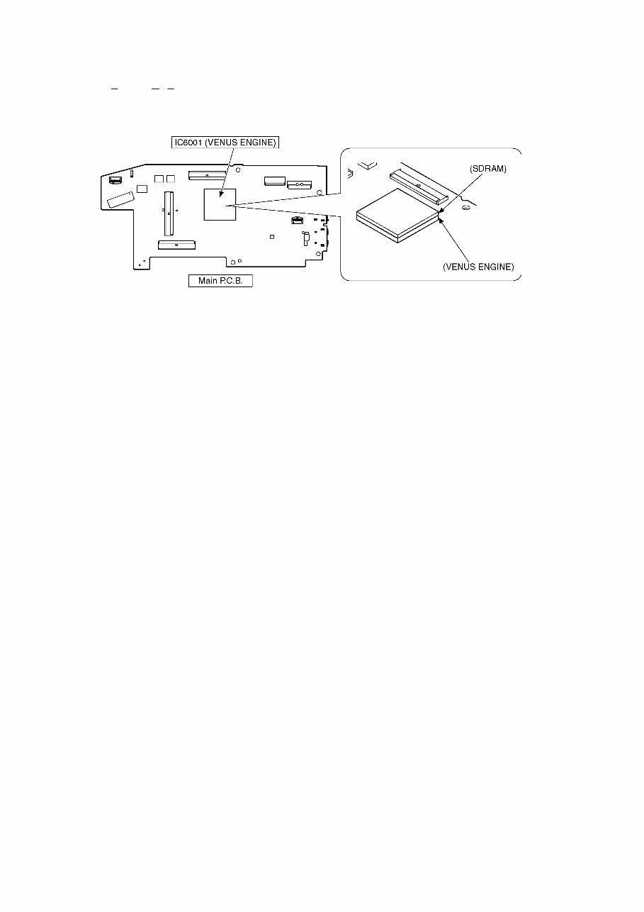
8 3.2.2. About VENUS ENGINE (IC6001) < Located on the Main P.C.B. > • The VENUS ENGINE (IC6001) consists of two IC chips, which are fixed together with solder. (It is so called, "P ackage O n P ackage" type of IC.) Caution: • During servicing, do not press down hard on the surface of IC6001. 3.2.3. About Flash ROM (IC6003) and Charging Control Microcomputer (IC1502) When the Flash Rom or Charging Control Microcomputer is replaced, it is need to adjust the firmware of the Charging Control Microcomputer to the one of the Flash ROM. For details, refer to "10.3.2. Adjustment Specifications". It may takes about 10 seconds. While doing the adjustment, don't turn the power off forcibly. (It cause the Charging Control Microcomputer crush, then the camera can not turn on.) 3.2.4. About Flexible Cable and Connector Do not touch carelessly so that the foreign body should not adhere to the terminal part of flexible cable and connector. Wipe off with a clean cloth and the cotton bud, etc. when the terminal part is dirty.
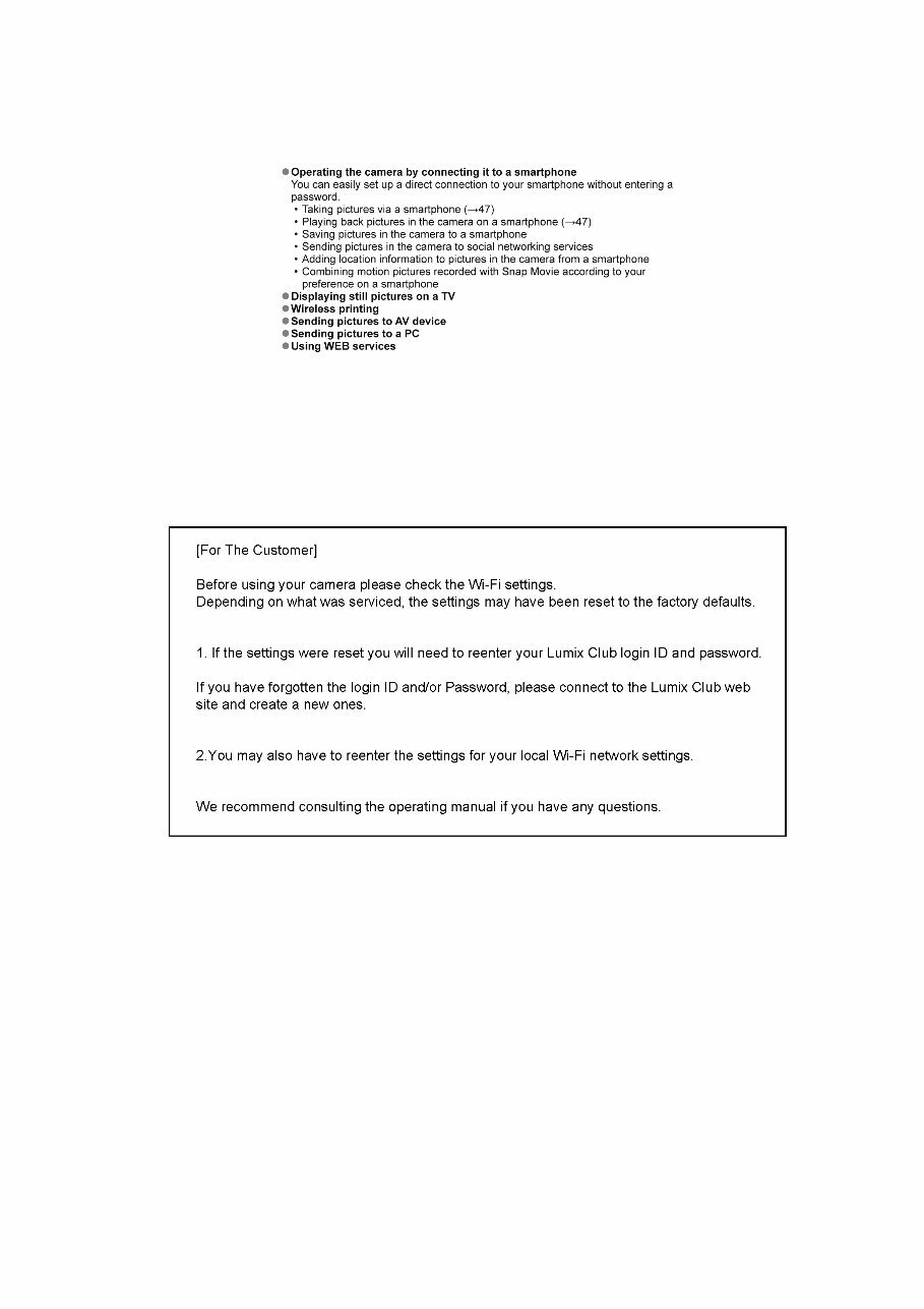
9 3.3. Service Notes 3.3.1. About Wi-Fi Function The page number in this chapter does not show the page number of this service manual. 3.3.2. Important Notice of Servicing This Camera unit has the personal information of wireless LAN connection the customer has registered. For the protection of private information, please erase the personal information after the completion of repair by "INITIAL SETTING". In addition, please print out the following documents, and pass to the customer with the Camera unit. Printing Material [Leaflet for Customer]
10 3.4. General Description About Lead Free Solder (PbF) The lead free solder has been used in the mounting process of all electrical components on the printed circuit boards used for this equipment in considering the globally environmental conservation. The normal solder is the alloy of tin (Sn) and lead (Pb). On the other hand, the lead free solder is the alloy mainly consists of tin (Sn), silver (Ag) and Copper (Cu), and the melting point of the lead free solder is higher approx.30 °C (86 °F) more than that of the normal solder. Definition of PCB Lead Free Solder being used Service caution for repair work using Lead Free Solder (PbF) • The lead free solder has to be used when repairing the equipment for which the lead free solder is used. • (Definition: The letter of is printed on the P.C.B. using the lead free solder.) • To put lead free solder, it should be well molten and mixed with the original lead free solder. • Remove the remaining lead free solder on the P.C.B. cleanly for soldering of the new IC. • Since the melting point of the lead free solder is higher than that of the normal lead solder, it takes the longer time to melt the lead free solder. • Use the soldering iron (more than 70W) equipped with the temperature control after setting the temperature at 350±30 °C (662±86 °F). Recommended Lead Free Solder (Service Parts Route.) • The following 3 types of lead free solder are available through the service parts route. SVKZ000001-----------(0.3mm 100g Reel) SVKZ000002-----------(0.6mm 100g Reel) SVKZ000003-----------(1.0mm 100g Reel) Note: * Ingredient: Tin (Sn) 96.5%, Silver (Ag) 3.0%, Copper (Cu) 0.5%. (Flex cored) The letter of is printed either foil side or components side on the P.C.B. using the lead free solder. (See right figure)
You're Reading a Preview
What's Included?
Lifetime Access
Fast Download Speeds
Online & Offline Access
Access PDF Contents & Bookmarks
Full Search Facility
Print one or all pages of your manual
$36.99
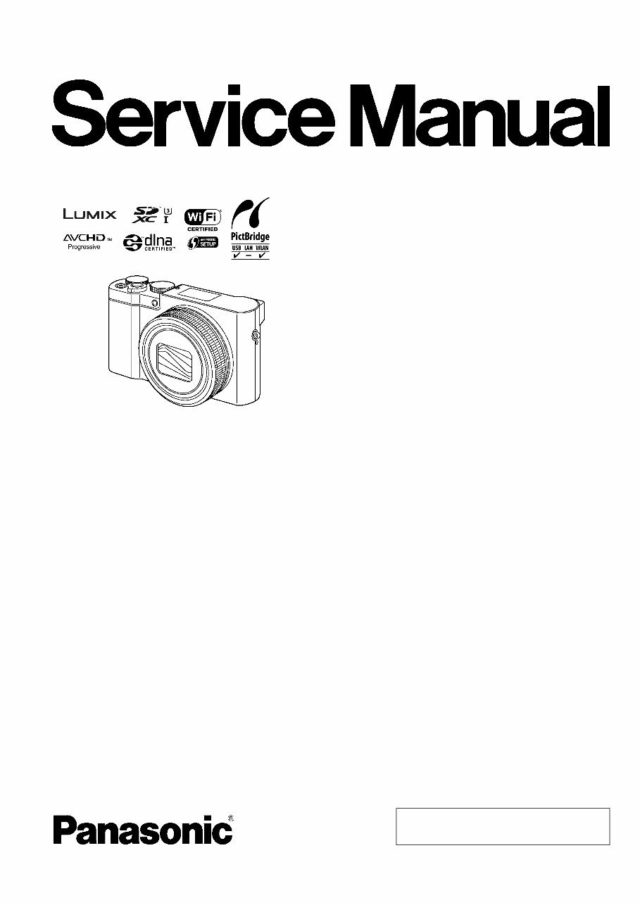
Panasonic Lumix DMC-TZ100 TZ101 TZ110 ZS100 ZS110 Service Manual
This service and repair manual for the Panasonic Lumix DMC TZ100, TZ101, TZ110, ZS100, and ZS110 cameras is an essential resource for troubleshooting and repairing your device. It is utilized by authorized Certified Panasonic Technicians and maintenance employees, making it equally valuable for professional mechanics and DIY enthusiasts.
The manual includes comprehensive content such as safety precautions, warnings, service navigation, specifications, location of controls and components, service mode, service fixture & tools, disassembly and assembly instructions, measurements and adjustments, block diagram, wiring connection diagram, as well as schematics, circuit boards, exploded views, and a full parts catalog.
It covers all worldwide models, including DMC-TZ100EB, DMC-TZ100EF, DMC-TZ100EG, DMC-TZ100EP, DMC-TZ101EF, DMC-TZ101EG, DMC-TZ110GA, DMC-TZ110GN, DMC-ZS100P, DMC-ZS100PP, DMC-ZS110GD, DMC-ZS110GH, and DMC-ZS110GK.
This detailed manual features step-by-step instructions and high-resolution images, ensuring the best possible guidance for servicing and repairing the device. It is available in format, providing instant access without any shipping fees or waiting time for postal delivery.
Specifications:
Language: English
Format: .PDF
Pages: 105
Reviews
Q&A
Recently Viewed
5,521,897Happy Clients
2,594,462eManuals
1,120,453Trusted Sellers
15Years in Business
Price:
Actual Price:
Panasonic Lumix DMC-TZ100 TZ101 TZ110 ZS100 ZS110 Service Manual




 Lifetime Access




