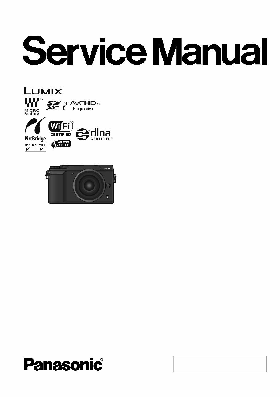
2 DMC-GX85GT DMC-GX85KP DMC-GX85KPP DMC-GX85KGC DMC-GX85KGD DMC-GX85KGH DMC-GX85KGN DMC-GX85WGK DMC-GX85CGC DMC-GX85CGK Colour [DMC-GX80/GX85] (K)...........Black Type (S)...........Silver Type (except EE) (T)...........Brown Type (except EE/EF/P/PP/GN) [DMC-GX80K/GX85K] (K)...........Black Type (S)...........Silver Type (except EE) (T)...........Brown Type (except EE/P/PP/GN) [DMC-GX80W/GX85W/GX80C/GX85C] (K)...........Black Type (S)...........Silver Type (T)...........Brown Type [DMC-GX80H] (K)...........Black Type (S)...........Silver Type DMC-GX80K/GX85K series: Interchangeable Lens (H-FS12032) is bundled. DMC-GX80W/GX85W series: Interchangeable Lens (H-FS12032/H-FS35100) are bundled. DMC-GX80C/GX85C series: Interchangeable Lens (H-H020A) is bundled. DMC-GX80H series: Interchangeable Lens (H-FS14140[-KA]) is bundled.
3 TABLE OF CONTENTS PAGE PAGE 1 Safety Precautions ----------------------------------------------- 4 1.1. General Guidelines---------------------------------------- 4 1.2. Leakage Current Cold Check--------------------------- 4 1.3. Leakage Current Hot Check (See Figure. 1) ------- 4 1.4. How to Discharge the E.Capacitor on Flash P.C.B.--------------------------------------------------------- 5 2 Warning -------------------------------------------------------------- 6 2.1. Prevention of Electrostatic Discharge (ESD) to Electrostatically Sensitive (ES) Devices---------- 6 2.2. How to Recycle the Lithium Ion Battery (U.S. Only) ---------------------------------------------------------- 6 2.3. How to Replace the Lithium Battery ------------------ 7 3 Service Navigation ----------------------------------------------- 8 3.1. Introduction-------------------------------------------------- 8 3.2. About service of bundled lenses----------------------- 8 3.3. Important Notice ------------------------------------------- 8 3.4. Service Notes----------------------------------------------14 3.5. General Description About Lead Free Solder (PbF)---------------------------------------------------------16 3.6. How to Define the Model Suffix (NTSC or PAL Model) -------------------------------------------------------17 4 Specifications ----------------------------------------------------22 4.1. Camera Body ----------------------------------------------22 4.2. Lens----------------------------------------------------------25 5 Location of Controls and Components ------------------27 5.1. Camera Body ----------------------------------------------27 5.2. Lens----------------------------------------------------------28 6 Service Mode -----------------------------------------------------29 6.1. Error Code Memory Function--------------------------29 7 Troubleshooting Guide ----------------------------------------31 7.1. Checking Method of Body and Interchangeable Lens -----------------------------------31 7.2. Wi-Fi Circuit ------------------------------------------------35 8 Service Fixture & Tools----------------------------------------36 8.1. Service Fixture and Tools-------------------------------36 8.2. Clean Box --------------------------------------------------38 8.3. When Replacing the Main P.C.B.---------------------38 8.4. Service Position-------------------------------------------39 9 Disassembly and Assembly Instructions ---------------40 9.1. Camera Body Part----------------------------------------40 9.2. Disassembly and Assembly Procedure for the Lens----------------------------------------------------------52 10 Measurements and Adjustments ---------------------------53 10.1. Matrix Chart for Replaced Part and Necessary Adjustment -------------------------------------------------53 11 Maintenance-------------------------------------------------------56 11.1. Notice in External Cleaning ----------------------------56 12 Block Diagram----------------------------------------------------57 12.1. Overall Block Diagram ----------------------------------57 12.2. System Control Block Diagram -----------------------58 12.3. Video/Audio Process(1) Block Diagram ------------59 12.4. Video/Audio Process(2) Block Diagram ------------60 12.5. Gyro/WiFi Block Diagram-------------------------------61 12.6. Flash/Hot Shoe Block Diagram -----------------------62 12.7. Lens Block Diagram -------------------------------------63 12.8. Power(1) Block Diagram--------------------------------64 12.9. Power(2) Block Diagram--------------------------------65 12.10. Power(3) Block Diagram--------------------------------66 13 Wiring Connection Diagram--------------------------------- 67 13.1. Interconnection Diagram ------------------------------- 67 14 Schematic Diagram -------------------------------------------- 68 15 Printed Circuit Board ------------------------------------------ 68 16 Exploded View and Replacement Parts List ----------- 68
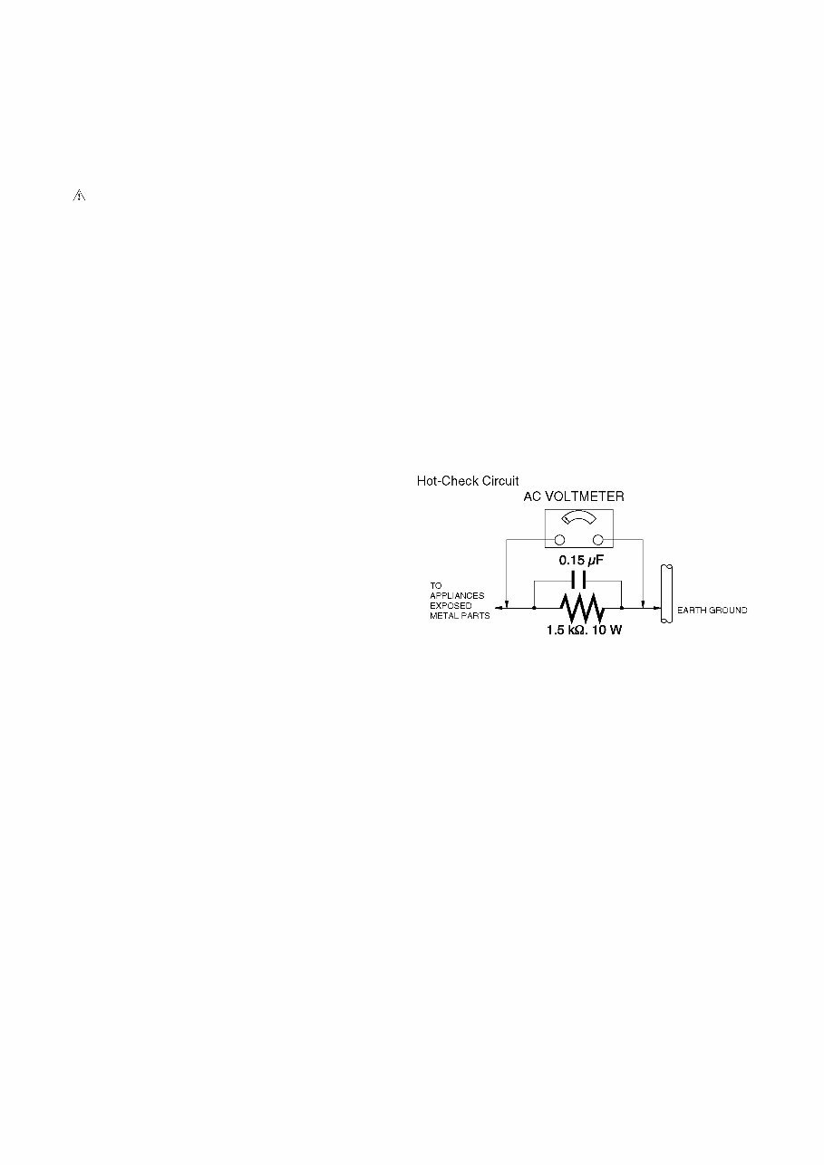
4 1 Safety Precautions 1.1. General Guidelines 1. IMPORTANT SAFETY NOTICE There are special components used in this equipment which are important for safety. These parts are marked by in the Schematic Diagrams, Circuit Board Layout, Exploded Views and Replacement Parts List. It is essen- tial that these critical parts should be replaced with manu- facturer’s specified parts to prevent X-RADIATION, shock, fire, or other hazards. Do not modify the original design without permission of manufacturer. 2. An Isolation Transformer should always be used during the servicing of AC Adaptor whose chassis is not isolated from the AC power line. Use a transformer of adequate power rating as this protects the technician from acci- dents resulting in personal injury from electrical shocks. It will also protect AC Adaptor from being damaged by acci- dental shorting that may occur during servicing. 3. When servicing, observe the original lead dress. If a short circuit is found, replace all parts which have been over- heated or damaged by the short circuit. 4. After servicing, see to it that all the protective devices such as insulation barriers, insulation papers shields are properly installed. 5. After servicing, make the following leakage current checks to prevent the customer from being exposed to shock hazards. 1.2. Leakage Current Cold Check 1. Unplug the AC cord and connect a jumper between the two prongs on the plug. 2. Measure the resistance value, with an ohmmeter, between the jumpered AC plug and each exposed metal- lic cabinet part on the equipment such as screwheads, connectors, control shafts, etc. When the exposed metal- lic part has a return path to the chassis, the reading should be between 1 M and 5.2 M. When the exposed metal does not have a return path to the chassis, the reading must be infinity. 1.3. Leakage Current Hot Check (See Figure. 1) 1. Plug the AC cord directly into the AC outlet. Do not use an isolation transformer for this check. 2. Connect a 1.5 k, 10 W resistor, in parallel with a 0.15 F capacitor, between each exposed metallic part on the set and a good earth ground, as shown in Figure. 1. 3. Use an AC voltmeter, with 1 k/V or more sensitivity, to measure the potential across the resistor. 4. Check each exposed metallic part, and measure the volt- age at each point. 5. Reverse the AC plug in the AC outlet and repeat each of the above measurements. 6. The potential at any point should not exceed 0.75 V RMS. A leakage current tester (Simpson Model 229 or equiva- lent) may be used to make the hot checks, leakage cur- rent must not exceed 1/2 mA. In case a measurement is outside of the limits specified, there is a possibility of a shock hazard, and the equipment should be repaired and rechecked before it is returned to the customer. Figure. 1
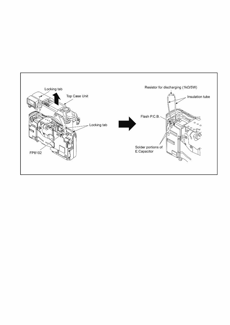
5 1.4. How to Discharge the E.Capacitor on Flash P.C.B. CAUTION: • Be sure to discharge the E.Capacitor on Flash P.C.B. before disassembling. • Be careful of the high voltage circuit on Flash P.C.B. when servicing. [Discharging Procedure] 1. Remove the Top Case Unit. 2. Put the insulation tube on the lead part of resistor (ERG5SJ102: 1kΩ / 5W). (An equivalent type of resistor may be used.) 3. Put the resistor between both terminals of E.Capacitor on the Flash P.C.B. for approx. 5 seconds. 4. After discharging, confirm that the E.Capacitor voltage is lower than 10V by using a voltmeter.
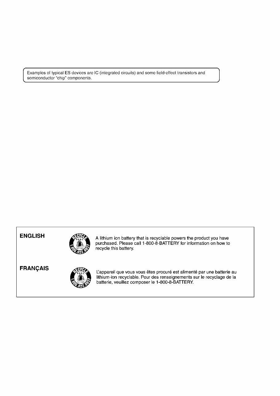
6 2 Warning 2.1. Prevention of Electrostatic Discharge (ESD) to Electrostatically Sensitive (ES) Devices Some semiconductor (solid state) devices can be damaged easily by static electricity. Such components commonly are called Elec- trostatically Sensitive (ES) Devices. The following techniques should be used to help reduce the incidence of component damage caused by electrostatic discharge (ESD). 1. Immediately before handling any semiconductor component or semiconductor-equipped assembly, drain off any ESD on your body by touching a known earth ground. Alternatively, obtain and wear a commercially available discharging ESD wrist strap, which should be removed for potential shock reasons prior to applying power to the unit under test. 2. After removing an electrical assembly equipped with ES devices, place the assembly on a conductive surface such as alumi- num foil, to prevent electrostatic charge buildup or exposure of the assembly. 3. Use only a grounded-tip soldering iron to solder or unsolder ES devices. 4. Use only an antistatic solder removal device. Some solder removal devices not classified as “antistatic (ESD protected)” can generate electrical charge sufficient to damage ES devices. 5. Do not use freon-propelled chemicals. These can generate electrical charges sufficient to damage ES devices. 6. Do not remove a replacement ES device from its protective package until immediately before you are ready to install it. (Most replacement ES devices are packaged with leads electrically shorted together by conductive foam, aluminum foil or compara- ble conductive material). 7. Immediately before removing the protective material from the leads of a replacement ES device, touch the protective material to the chassis or circuit assembly into which the device will be installed. CAUTION : Be sure no power is applied to the chassis or circuit, and observe all other safety precautions. 8. Minimize bodily motions when handling unpackaged replacement ES devices. (Otherwise harmless motion such as the brushing together of your clothes fabric or the lifting of your foot from a carpeted floor can generate static electricity (ESD) suf- ficient to damage an ES device). 2.2. How to Recycle the Lithium Ion Battery (U.S. Only)
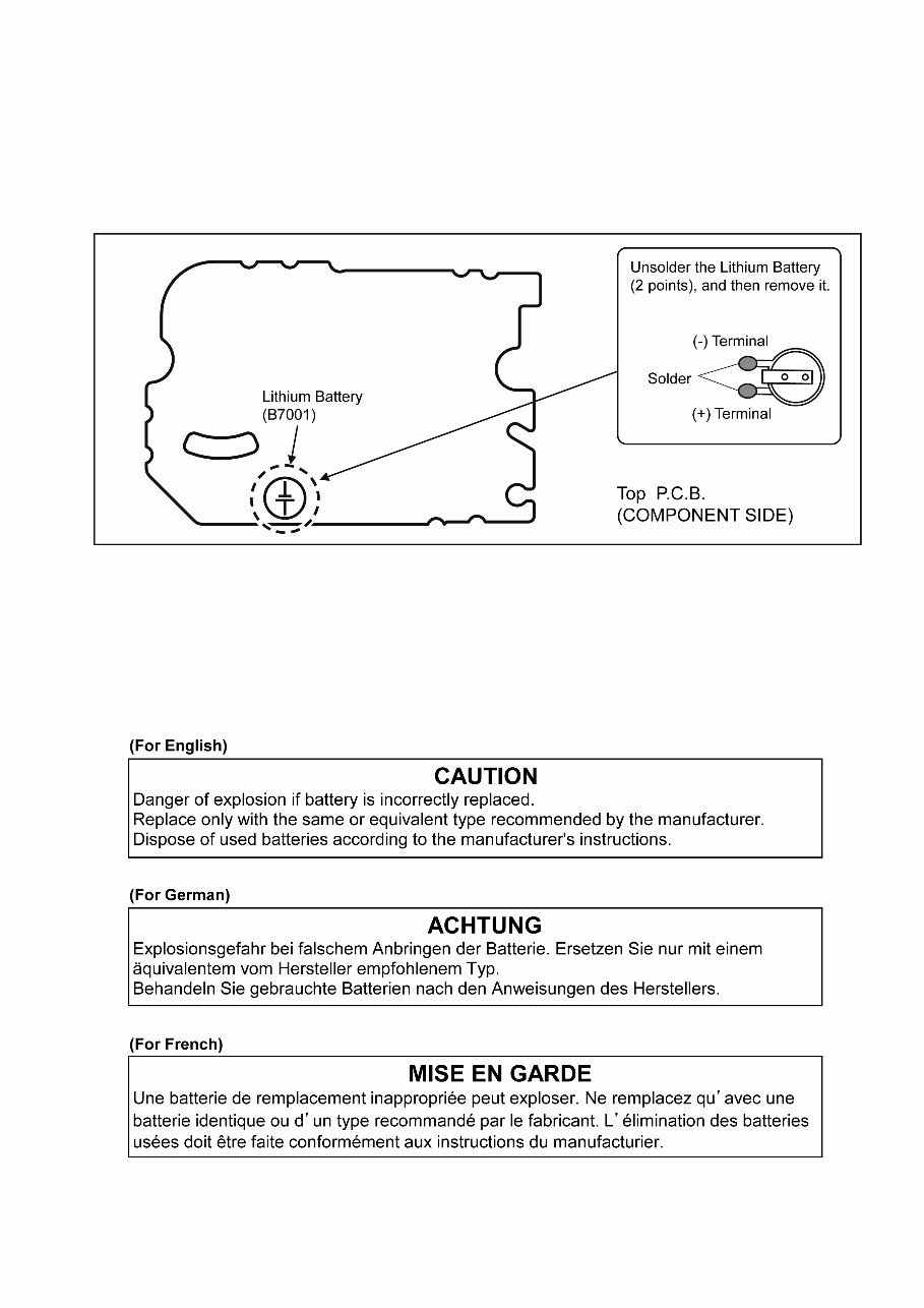
7 2.3. How to Replace the Lithium Battery 2.3.1. Replacement Procedure 1. Remove the TOP P.C.B.. (Refer to Disassembly Procedures.) 2. Unsolder the each soldering point of electric lead terminal for Lithium battery (Ref. No. “B7001” at component side of TOP P.C.B.) and remove the Lithium battery together with electric lead terminal. Then replace it into new one. NOTE: The Lithium battery includes electric lead terminals. NOTE: This Lithium battery is a critical component. It must never be subjected to excessive heat or discharge. It must therefore only be fitted in requirement designed specifically for its use. Replacement batteries must be of same type and manufacture. They must be fitted in the same manner and location as the original battery, with the correct polarity contacts observed. Do not attempt to re-charge the old battery or re-use it for any other purpose. It should be disposed of in waste products destined for burial rather than incineration. NOTE: Above caution is applicable for a battery pack which is for DMC-GX80/GX85/GX80K/GX85K/GX80W/GX85W/GX80C/GX85C/ GX80H series, as well.
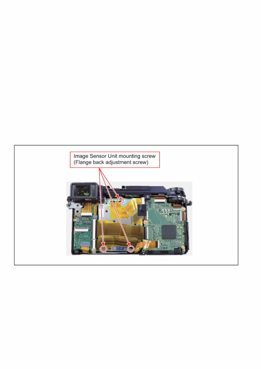
8 3 Service Navigation 3.1. Introduction This service manual contains technical information, which allow service personnel’s to understand and service this model. Please place orders using the parts list and not the drawing reference numbers. If the circuit is changed or modified, the information will be followed by service manual to be controlled with original service manual. 3.2. About service of bundled lenses Please refer to the following service manuals about Disassembly and Assembly or Maintenance of bundled lenses. • H-FS12032PP/E/GK: Order No.DSC1311036CE • H-FS35100PP/E/GK: Order No.DSC1410024CE • H-H020APP/E/GK: Order No.DSC1307028CE • H-FS14140PP/E/GK: Order No.DSC1305023CE/Order No.DSC1506509SE 3.3. Important Notice *When servicing, it is recommended dealing with Clean box. (Refer to “8.2. Clean Box” section of this service manual for details.) 3.3.1. Camera Body Unit 3.3.1.1. About Flange back adjustment When turning the image sensor unit mounting screw even a little or removing, the “simplicity flange back adjustment” is need. Perform the “simplicity flange back adjustment” according to contents described in “10 Measurement and Adjustment” section of this service manual. 3.3.1.2. About Shutter Unit (Ref. 80) Before exchanging the “shutter unit”, confirm that the symptom and/or phenomenon is not due to the setting of functions. Important: After replacing the shutter unit, the shutter unit data has to be stored to the unit. The shutter unit supplied as service parts has affix the label of own configure data. By inputting second line to fourth line of these data into the adjustment software and writing these data to Flash-ROM (IC6003), the shutter adjustment becomes needless. In addition, the adjustment software can read data encoded to QR Code by using WEB camera with a close-up function. Refer to the adjustment instruction in the adjustment software for details.
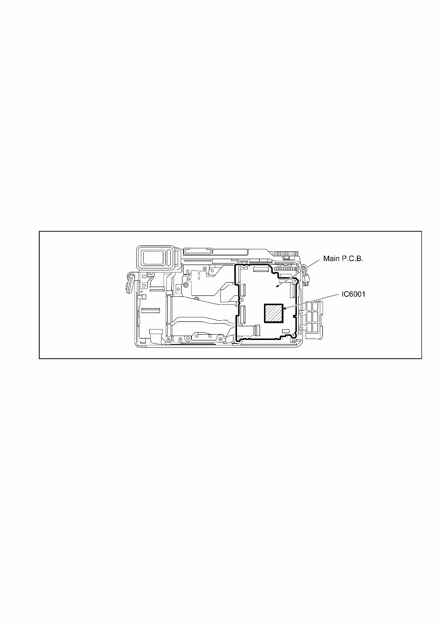
9 3.3.1.3. About Main P.C.B. (Ref.1) & Flash-ROM (IC6003) Before exchanging the “Main P.C.B.”, confirm that the symptom and/or phenomenon is not due to the setting of functions. Important: When cannot be repaired in the IC exchange, and in the case of performing the “Main P.C.B.” exchange, carry out any of following. In the case of exchanging the Flash-ROM (IC6003) is same way too. 1. When the camera power can be ON, and camera body and adjustment software can be communicated: Before replacing the “Main P.C.B. and/or Flash-ROM”, proceed the EEPROM data backup from the unit. After replacing the Main P.C.B. and/or Flash-ROM, overwrite the EEPROM data with backup data from the unit first, then proceed the adjustment /inspection. (Almost adjustment/inspection items can be omitted.) Refer to the adjustment instruction in the adjustment software for details. 2. When the camera power cannot be ON, or camera body and adjustment software cannot be communicated: Almost full adjustment/inspection must be performed after replacing the “Main P.C.B. and/or Flash-ROM”. Refer to the adjustment instruction in the adjustment software for details. Notes after replacement: Make sure the camera body firmware is latest version. 3.3.1.4. About Venus Engine (IC6001) [Located on the Main P.C.B.]: • The Venus Engine (IC6001) consists of two IC chips, which are fixed together with solder. (The so called, “Package On Package” type IC.) NOTE: • During servicing, do not press down hard on the surface of IC6001.
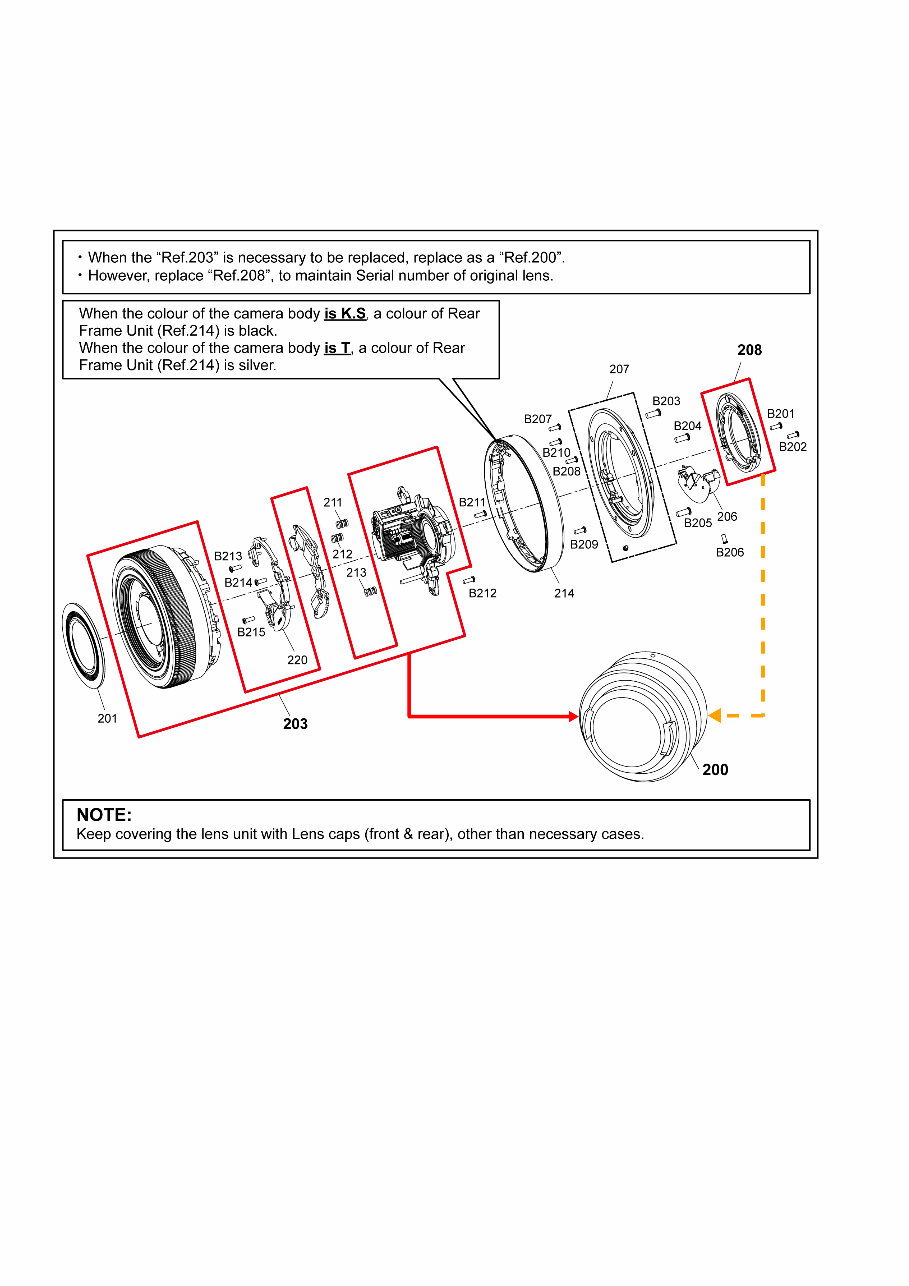
10 3.3.2. Lens Unit (Interchangeable Lens: H-FS12032) 3.3.2.1. About Lens Main Unit (Ref. 203) 1. Lens Main Unit (Ref. 203) is not supplied due to difficulty of the transportation issue (Fragile, Dust-free packing), and requires critical lens adjustments. Therefore, any needs of the “Lens Main Unit” (Ref. 203), carefully confirm its performance in advance. 2. Once “Lens Main Unit” (Ref. 203) is confirmed as defective, place order “Lens Unit” (Ref. 200) and replace Shading Frame (Ref. 208), to maintain Serial number of owner’s original lens.
You're Reading a Preview
What's Included?
Lifetime Access
Fast Download Speeds
Online & Offline Access
Access PDF Contents & Bookmarks
Full Search Facility
Print one or all pages of your manual
$39.99
Panasonic Lumix DMC GX80 GX85 Service Manual Repair Guide
This service and repair manual for the Panasonic Lumix DMC GX80 GX85 Interchangeable Lens Camera is an essential resource for both professional technicians and DIY enthusiasts. It is the same manual used by authorized Certified Panasonic Technicians and maintenance employees, providing comprehensive guidance for troubleshooting and repairing the camera.
The manual includes:
Safety Precautions
Warning
Service Navigation
Specifications
Location of Controls and Components
Service Mode
Service Fixture & Tools
Disassembly and Assembly Instructions
Measurements and Adjustments
Block Diagram
Wiring Connection Diagram
In addition, it contains schematics, circuit boards, exploded views, and a full parts catalog, providing detailed information not typically found in standard service manuals.
This manual covers all worldwide models of the DMC-GX80 and DMC-GX85, ensuring its relevance for a wide range of users.
Featuring step-by-step instructions and high-resolution images, this official service and repair manual ensures that the repair or service of the device is carried out effectively and accurately.
It is important to note that this is the official service and repair manual in PDF format, guaranteeing high-quality, original content without any scanned-in or bootlegged copies.
With instant access upon purchase, there are no shipping fees or waiting for postal delivery, allowing users to commence repairs within minutes.
Specifications:
Language: English
Format: PDF
Pages: 124
Reviews
Q&A
Recently Viewed
5,521,897Happy Clients
2,594,462eManuals
1,120,453Trusted Sellers
15Years in Business
Price:
Actual Price:
Panasonic Lumix DMC GX80 GX85 Service Manual Repair Guide



 Lifetime Access




