作成承認印 配布許可印 Copyright c 2008 by Nikon Corporation. All Rights Reserved. 無断転載を禁ず !! M サービス 計画課 Printed in Japan SEP 2008 VBA23001-R.3762.A VBA23001 REPAIR MANUAL INC
VBA23001-R.3762 .A - D90 - Contents Points to notice for Disassembly and Assembly .............................................................................................................. D1 Disassembly 1. External area Bottom cover ........................................................................... D2 Removal of Back cover ................................................................... D3 2. Back cover Rear display FPC unit ..................................................................... D4 TFT monitor............................................................................ D8 Button / SW-related ...................................................................... D9 SD cover unit ........................................................................... D 10 Speaker unit ............................................................................ D 12 DG-shield plate ......................................................................... D 12 DG PCB unit ........................................................................... D 13 Image sensor unit ........................................................................ D 14 A/M cover plat .......................................................................... D 15 SB pop-up .............................................................................. D 15 Front cover unit ......................................................................... D 16 Grip rubber unit ......................................................................... D 17 I/F cover............................................................................... D 18 Removal of top cover ..................................................................... D 20 3. Top cover AF-assist lamp unit ...................................................................... D 23 Top cover FPC unit ...................................................................... D 23 AE-L button ............................................................................ D 28 Top cover grip button .................................................................... D 28 Power dial .............................................................................. D 29 Hot shoe ............................................................................... D 30 SB upper cover .......................................................................... D 30 SB lower control unit..................................................................... D 31 Remote control unit ...................................................................... D 34 M/D FPC unit .......................................................................... D 34 Delete button ........................................................................... D 35 Mode dial .............................................................................. D 35 Microphone ............................................................................ D 35 Removal of the main condenser ............................................................. D 37 Main PCB unit .......................................................................... D 38 INC
VBA23001-R.3762 .A - D90 - 4. Separation of Front body from Rear body Eyepiece mold ......................................................................... D 40 5. Rear body SB/IF PCB ............................................................................. D 42 DC/DC PCB ........................................................................... D 42 Imaging power PCB unit .................................................................. D 44 Bottom plate unit ........................................................................ D 45 Power drive PCB unit .................................................................... D 46 Battery contact-spring .................................................................... D 48 Eyelet ................................................................................. D 50 Buzzer unit............................................................................. D 51 Drip-proof sponge ....................................................................... D 51 Dust-proof tape .......................................................................... D 52 6. Separation of Prism box unit from Front body unit ............................................... D 53 7. Prism box unit Metering FPC unit ....................................................................... D 54 Inside finder LCD unit.................................................................... D 54 Screen box ............................................................................. D 55 Penta prism ............................................................................ D 57 Penta prism FPC unit ..................................................................... D 59 Eyepiece barrel unit ...................................................................... D 60 8. Front body unit SB PCB ............................................................................... D 61 Shutter unit ............................................................................ D 62 AF CCD unit ........................................................................... D 62 Front body FPC ......................................................................... D 64 Aperture control unit ..................................................................... D 66 AF driving base ........................................................................ D 69 Bayonet ............................................................................... D 70 A/M change sw ......................................................................... D 72 Release button .......................................................................... D 73 F-min SW ............................................................................. D 74 Preview sw ............................................................................. D 74 Main mirror unit ........................................................................ D 75 INC
VBA23001-R.3762 .A - D90 - Assembly / Adjustment 1. Front body unit Main mirror unit ......................................................................... A3 Preview SW ............................................................................ A4 F-min SW .............................................................................. A5 Release button .......................................................................... A5 A/M change SW ......................................................................... A7 Bayonet ................................................................................ A8 AF driving base ......................................................................... A 10 Aperture control PCB ..................................................................... A 11 Front body FPC ......................................................................... A 14 AF CCD unit............................................................................ A 17 Shutter unit ............................................................................. A 18 SB PCB................................................................................ A 20 Height adjustment of AF coupling shaft ....................................................... A 21 Height adjustment of Aperture lever ....................................................... A 21 Angle inspection and adjustment of Main mirror and Sub-mirror ................................... A 22 Angle adjustment of Main mirror and sub-mirror ............................................... A 23 2. Prism box Eyepiece barrel unit ...................................................................... A 24 Penta prism FPC unit ..................................................................... A 25 Penta prism ............................................................................. A 25 Screen box ............................................................................. A 28 Inside finder LCD unit .................................................................... A 30 Metering FPC unit 1 ...................................................................... A 30 3. Rear body Dust-proof tape .......................................................................... A 32 Drip-proof sponge ....................................................................... A 32 Buzzer unit ............................................................................. A 33 Eyelet ................................................................................. A 34 Battery contact spring ..................................................................... A 36 Power drive PCB unit ..................................................................... A 37 Bottom plate unit ........................................................................ A 38 Imaging power PCB unit .................................................................. A 39 DC/DC PCB ............................................................................ A 40 SB/IF PCB unit .......................................................................... A 43 INC
VBA23001-R.3762 .A - D90 - 4 .Mounting Front body on Rear body. Eyepiece mold .......................................................................... A 44 Inspection and Adjustment of Body back .................................................. A 45 Main PCB ............................................................................. A 48 Mount the main condenser ................................................................ A 50 5. Top cover Microphone............................................................................. A 52 Mode dial .............................................................................. A 52 Delete button ........................................................................... A 53 M/D FPC unit ........................................................................... A 53 Remote control unit ...................................................................... A 54 SB lower control unit ..................................................................... A 55 SB upper cover .......................................................................... A 57 Hot shoe ............................................................................... A 58 Power dial .............................................................................. A 59 Top cover grip button ..................................................................... A 60 AE-L button ............................................................................ A 60 Top cover FPC unit ...................................................................... A 61 AF assist lamp unit ....................................................................... A 65 Mount the top cover on the body ............................................................ A 66 I/F cover ............................................................................... A 69 Grip rubber unit ......................................................................... A 70 Front cover unit ......................................................................... A 71 A/M cover plate ......................................................................... A 72 Image sensor unit ........................................................................ A 73 DG PCB unit............................................................................ A 74 Inspection and adjustment of AE CCD positioning .............................................. A 75 Battery check voltage inspection ............................................................ A 77 DG shield plate .......................................................................... A 78 Speaker unit ............................................................................ A 78 Accuracy inspection and adjustment (Camera body exc. Imaging) ............................. A 79 D90 Inspection and Adjustment Software (J65119) .............................................. A 80 Procedure for installing USB driver ....................................................... A 84 Necessary adjustments when parts are replaced Necessary adjustments when parts are replaced(Camera)....................................... A 86 AE inspection and adjustment .............................................................. A 87 AF inspection and adjustment .............................................................. A 89 October. 2. 2008 Changed page (Overall revision) INC
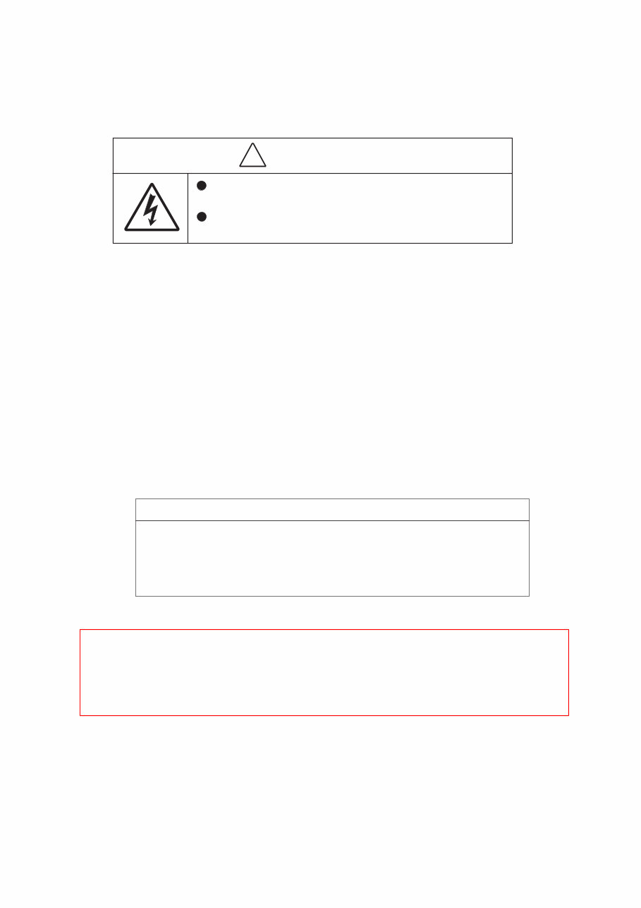
VBA23001-R.3762 .A - D1 ・ D90 - Caution: ① In disassembly/(re)assembly, be sure to use conductive mat (J5033) and wrist strap (J5033-5), in order to protect electric parts from static electricity. ② Before disassembling, be sure to remove batteries or AC power cord. ③ In disassembling, be sure to memorize the processing state of wires and FPC, screws to be fixed and their types, etc. ④ The low-pass filter of the image PCB/base plate is easily damaged. Handle it very carefully. Points to notice for Disassembly and Assembly WARNING There are high voltege parts inside. Be careful of this electric shock, when you remove the cover. You must discharge the main condenser according to the instruction of this repair manual after you remove the cover. ! Caution: When "Separation of Front body from Rear body", "Disassembly of Image sensor unit" and "Disassembly of Bayonet" are performed, be sure to carry out "RESET AF-DEFOCUS COMPENSATION" of the D90 adjustment software after assembly. Points to notice for Lead-free solder products ・ Lead-free solder is used for this product. ・ For soldering work, the special solder and soldering iron are required. ・ Do NOT mix up lead-free solder with traditional solder. INC
VBA23001-R.3762 .A - D2 ・ D90 - ・Tilt the battery cover unit (#B151) at approx. a 35 battery cover unit (#B151) at approx. a 35-degree angle, and pull it out. ・Take out the two screws (#657), the two screws (#658), the screw (#661), and the two screws (#692). Take out the two screws (#657), the two screws (#658), the screw (#661), and the two screws (#692). ・Remove the bottom cover unit (#25). Remove the bottom cover unit (#25). 35° Battery chamber unit (#B151) (#657)×1 (#658)×2 (#661)×1 (#692)×2 (#657) ×1 1. External area Disassembly Bottom cover Bottom cover unit (#25) INC
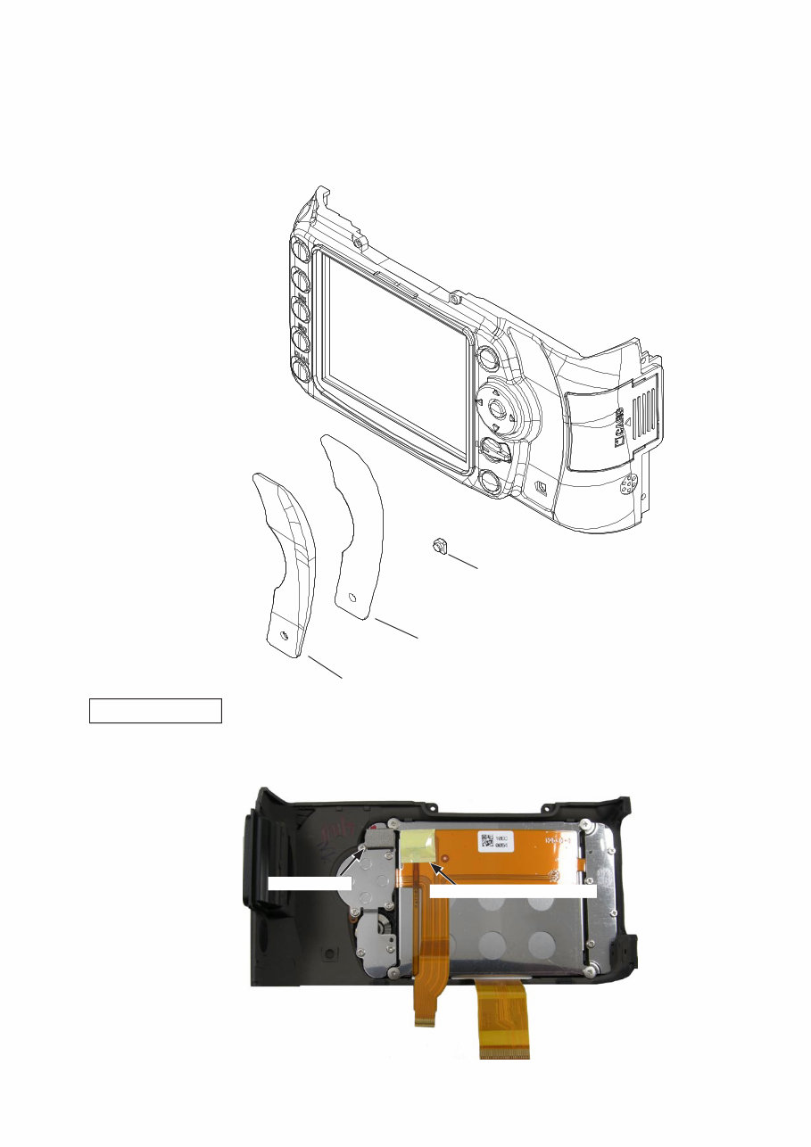
VBA23001-R.3762 .A - D3 ・ D90 - ・Slacken the grip side of the cover first, and then remove the cover wholly. ・Disconnect the FPC of the back cover from the connector on the DG PCB unit. Disconnect the FPC of the back cover from the connector on the DG PCB unit. ・Take out the two screws (#608). Take out the two screws (#608). ・Take out the four screws (#657). Take out the four screws (#657). Screw (#608)×2 Screw (#657)×4 Removal of Back cover INC
VBA23001-R.3762 .A - D4 ・ D90 - ・Peel off the cover rubber (#407) and the Peel off the cover rubber (#407) and the double-stick tape (#409). ・Remove the SD access lamp window (#408). Remove the SD access lamp window (#408). Cover rubber (#407) Double-stick tape (#409) SD access lamp window (#408) ・Remove the gasket (#483). Remove the gasket (#483). ・Peel off the tape [TA-0005 (12.5 Peel off the tape [TA-0005 (12.5×12.5)]. Gasket (#483) Rear display FPC unit 2. Back cover Tape [TA-0005 (12.5 × 12.5)] INC
Are you experiencing issues with your Nikon D90 SLR Camera? Instead of spending a significant amount on repairs or replacements, why not take matters into your own hands?
Gain access to the same service and repair manual utilized by Official Certified Nikon Technicians. This resource will equip you with the knowledge and skills to effectively troubleshoot and repair your SLR Camera.
Within this manual, you will delve into:
Safety & Precautions
Product Specifications
Disassembly & Reassembly
Adjustments
Troubleshooting
Exploded Views
Expect a comprehensive and meticulously illustrated guide, complete with images and step-by-step instructions for optimal device servicing and repair.
Conveniently print this manual from any computer and printer. Rest assured, this is the OFFICIAL and COMPLETE Nikon Factory Workshop manual, ensuring the highest resolution for top-quality printed pages.
Enjoy INSTANT access post-payment, eliminating shipping costs and delays. You can promptly commence with your repair tasks!