

Nikon D40 Full Service Manual
What's Included?
Fast Download Speeds
Online & Offline Access
Access PDF Contents & Bookmarks
Full Search Facility
Print one or all pages of your manual
作成承認印 配布許可印
VBA15001-R.3701.A
Printed in Japan Nov 2006
Silver VBA15101
Black VBA15001
Copyright© 2006 by NIKON CORPORATION.
All Rights Reserved.
無断転載を禁ず!!
M
サービス
計画課
REPAIR MANUAL
INC
VBA15001-R.3701.A
- M ・ -
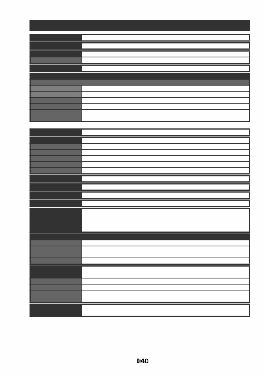
Specifications
Type Single-lens reflex digital camera with interchangeable lenses
Effective pixels 6.1 million
CCD 23.7 × 15.6 mm; total pixels: 6.24 million
Image size (pixels) • 3,008×2,000 (Large) • 2,256×1,496 (Medium) • 1,504×1,000 (Small)
Lens mount Nikon F mount with AF coupling and AF contacts
Compatible lenses
*
Type G or D AF Nikkor
AF-S, AF-I All functions supported
Other Type G or D Nikkor All functions supported except autofocus
Micro Nikkor 85 mm f/2.8D Can only be used in mode M; all other functions supported except autofocus
Other AF Nikkor
†
/AI-P Nikkor All functions supported except autofocus and 3D color matrix metering II
Non-CPU Can be used in mode M, but exposure meter does not function; electronic range finder
can be used if maximum aperture is f/5.6 or faster.
* IX Nikkor lenses can not be used †Excluding lenses for F3AF
Picture angle Equivalent in 35-mm format is approximately 1.5 times lens focal length.
Viewfinder Fixed eye-level penta-Dach mirror type
Diopter –1.7–+0.5m
-1
Eyepoint 18mm (–1.0m
-1
)
Focusing screen Type B BriteView clear matte screen Mark V with superimposed focus brackets
Frame coverage Approximately 95% of lens (vertical and horizontal)
Magnification Approximately 0.8 × (50-mm lens at infinity; –1.0 m
-1
)
Reflex mirror Quick return
Lens aperture Electronically controlled with instant return
Self-timer Electronically controlled timer with 2, 5, 10 or 20 s duration
Focus-area selection Focus area can be selected from 3 focus areas
Lens servo • Autofocus (AF): Instant single-servo AF (AF-S); continuous-servo AF (AF-C); auto AF-
S/AF-C selection (AF-A); predictive focus tracking activated automatically according
to subject status
• Manual focus (M)
Storage
Media SD (Secure Digital) memory cards; camera supports SDHC
File system Compliant with Design Rule for Camera File System (DCF) 2.0 and Digital Print Order
Format (DPOF)
Compression • NEF (RAW): compressed 12-bit • JPEG: JPEG baseline-complaint
Autofocus TTL phase detection by Nikon Multi-CAM 530 autofocus sensor module with AF-assist
illuminator (range approximately 0.5–3.0 m/1 ft. 8 in.–9 ft. 10 in.)
Detection range –1.0 – +19 EV (ISO 100 at 20 °C/68 °F)
AF-area mode Single-area AF, dynamic-area AF, dynamic-area AF with closest subject priority
Focus lock Focus can be locked by pressing the shutter-release button halfway (single-servo AF)
or by pressing the AE-L/AF-L button
ISO sensitivity (Recom-
mended Exposure Index)
200 – 1600 in steps of 1 EV with additional setting one step over 1600
INC
VBA15001-R.3701.A
- M ・ -
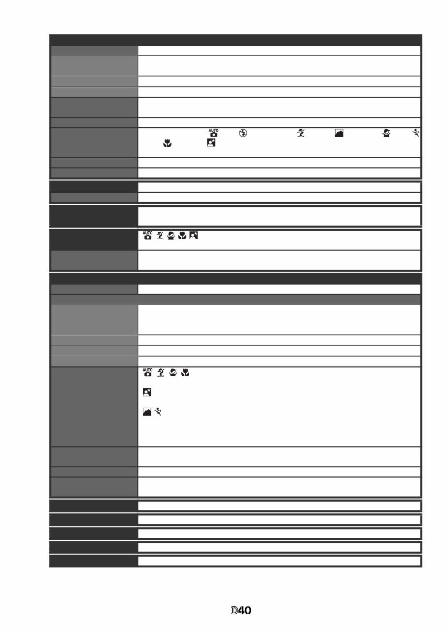
Exposure
Metering Three-mode through-the-lens (TTL) exposure metering
Matrix 3D color matrix metering II (type G and D lenses); color matrix metering II (other CPU
lenses); metering performed by 420-segment RGB sensor
Center-weighted Weight of 75% given to 8-mm circle in center of frame
Spot Meters 3.5-mm circle (about 2.5% of frame) centered on active focus area
Range (ISO 100 equivalent,
f/1.4 lens, 20 °C/68 °F)
0 – 20 EV (3D color matrix or center-weighted metering)
2 – 20 EV (spot metering)
Exposure meter coupling CPU coupling
Digital Vari-Program/
exposure modes
Digital Vari-Program ( auto, auto/no flash, portrait, landscape, child,
sports, close-up, night portrait); programmed auto (P) with flexible program;
shutter-priority auto (S); aperture-priority auto (A); manual (M)
Exposure compensation –5 – +5 EV in increments of
1
/ 3 EV
Exposure lock Exposure locked at detected value with AE-L/AF-L button
Shutter Combined mechanical and CCD electronic shutter
Speed 30–¼,000 s in steps of
1
/ 3 EV, bulb
White balance Auto (TTL white balance with 420-segment RGB sensor); six manual modes with fine
tuning and preset white balance
Built-in flash • , , , , : Auto flash with auto pop-up
• P, S, A, M: Manual pop-up with button release
Guide number (m/ft) • Approximately 17/55 at ISO 200 and 20 °C / 68 °F (manual 18/59)
• Approximately 12/39 at ISO 100 and 20 °C / 68 °F (manual 13/42)
Flash
Sync contact X-contact only; flash synchronization at shutter speeds of up to
1
/ 500 s
Flash control
TTL TTL flash control by 420-segment RGB sensor. i-TTL balanced fill-flash for digital SLR
and standard i-TTL fill-flash for digital SLR available when CPU lens is used with built-in
flash, SB-400, SB-800, and SB-600
Auto aperture Available with SB-800 and CPU lens
Non-TTL auto Available with such Speedlights as SB-800, 80DX, 28DX, 28, 27, and 22s
Range-priority manual Available with SB-800
Flash mode • : Auto, auto with red-eye reduction; fill-flash and red-eye reduction
available with optional Speedlight
• : Auto, auto slow sync, auto slow sync with red-eye reduction; slow sync and slow
sync with red-eye reduction available with optional Speedlight
• , : Fill-flash and red-eye reduction available with optional Speedlight
• P, A: Fill flash, rear-curtain with slow sync, slow sync, slow sync with red-eye reduction,
red-eye reduction
• S, M: Fill flash, rear-curtain sync, red-eye reduction
Flash-ready indicator Lights when built-in flash or SB-series Speedlight such as 400, 800, or 600 is fully
charged; blinks for about 3s after flash is fired at full output
Accessory shoe Standard ISO hot-shoe contact with sync, signal, and ground contacts and safety lock
Nikon Creative Lighting
System
Supported with built-in flash, SB-400, SB-800, and SB-600; Advanced Wireless Lighting
supported with SB-800 or SU-800 as Commander.
Monitor 2.5 in., 230,000-dot, low-temperature polysilicon TFT LCD with brightness adjustment
Video output Can be selected from NTSC and PAL
External interface USB 2.0 Hi-speed
Tripod socket ¼ in. (ISO 1222)
Firmware upgrades Firmware can be upgraded by user
INC
VBA15001-R.3701.A
- M ・ -
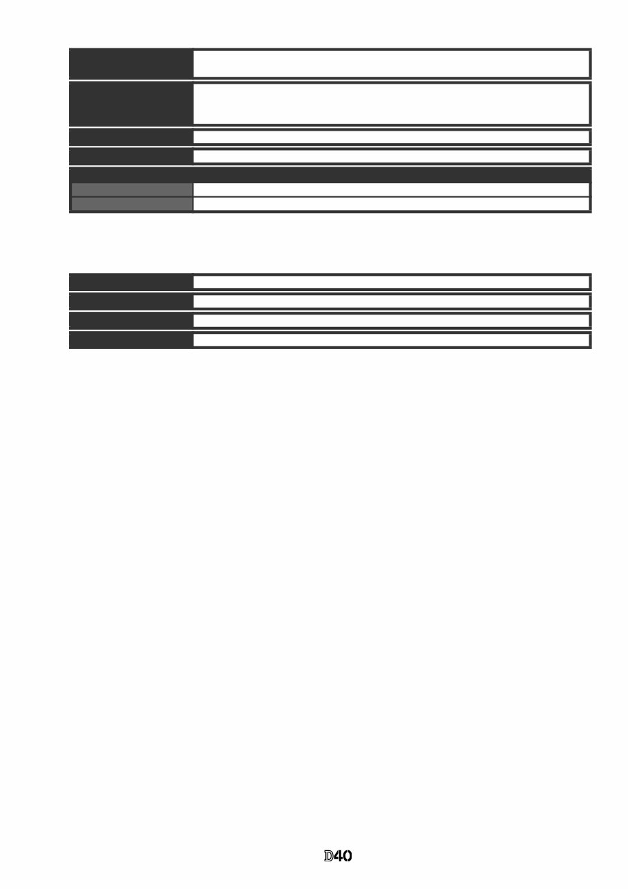
Unless otherwise stated, all figures are for a camera with a fully-charged battery operating at an ambi-
ent temperature of 20 °C (68 °F).
EN-EL9 Rechargeable Li-ion Battery
Supported languages Chinese (Simplified and Traditional), Dutch, English, Finnish, French, German, Italian,
Japanese, Korean, Polish, Portuguese, Russian, Spanish, Swedish
Power source • One rechargeable Nikon EN-EL9 Li-ion battery; charging voltage (MH-23 quick
charger): 7.4 V DC
• EH-5 AC adapter (available separately; requires optional EP-5 AC adapter connector)
Dimensions (W×D×H) Approximately 126×64×94mm (5.0×2.5×3.7in.)
Approximate weight 475 g (1 lb. 1 oz.) without battery, memory card, or body cap
Operating environment
Temperature 0–+40°C (+32–104°F)
Humidity Less than 85% (no condensation)
Type Rechargeable lithium-ion battery
Rated capacity 7.4V/1000mAh
Dimensions (W×D×H) Approximately 36×56×14mm (1.4×2.2×0.6in.)
Approximate weight 51 g (1.8 oz.), excluding power cable
INC
- D・ -
VBA15001-R.3701.A
Points to notice for Disassembly / Assembly
Caution:
Whenever "Separation of Front and rear bodies", "Disassembly of CCD/FPC unit", or
"Disassembly of Bayonet" are performed, be sure to perform "RESET AF-DEFOCUS
COMPENSATION" of camera adjustment software after reassembling.
WARNING
Due to an internal high voltage area, take extra care not to get
an electric shock when detaching covers.
After removing covers, be sure to discharge the main
condenser according to the instructions of repair manuals.
Note:
① When disassembling/(re)assembling, be sure to use the conductive mat (J5033) and wrist strap (J5033-5)
for static protection of electrical parts.
② Before disassembling, be sure to remove batteries or AC power wires.
③ When disassembling, make sure to memorize the processing state of wires and FPC, screws to be fixed
and their types, etc.
④ Because the low pass filter of the imaging CCD PCB is easily damaged, handle it with enough care.
⑤ is indicated in this manual when NK screw is used. Usually the same "NK" screw can be used
approx. up to three times.
(NK screw = Loose-proofing screw to which the adhesive is already applied and firmly fixed when
screwed in.)
Points to notice for Lead-free solder products
・ Lead-free solder is used for this product.
・ For soldering work, the special solder and soldering iron are required.
・ Do NOT mix up lead-free solder with traditional solder.
・ Use the special soldering iron respectively for lead-free solder and lead solder.
They cannot be used in common.
Changed page △×
M
サービス
計画課
Feb.05.2007
△ (Addition)
NK
INC
- D2・ -
VBA15001-R.3701.A
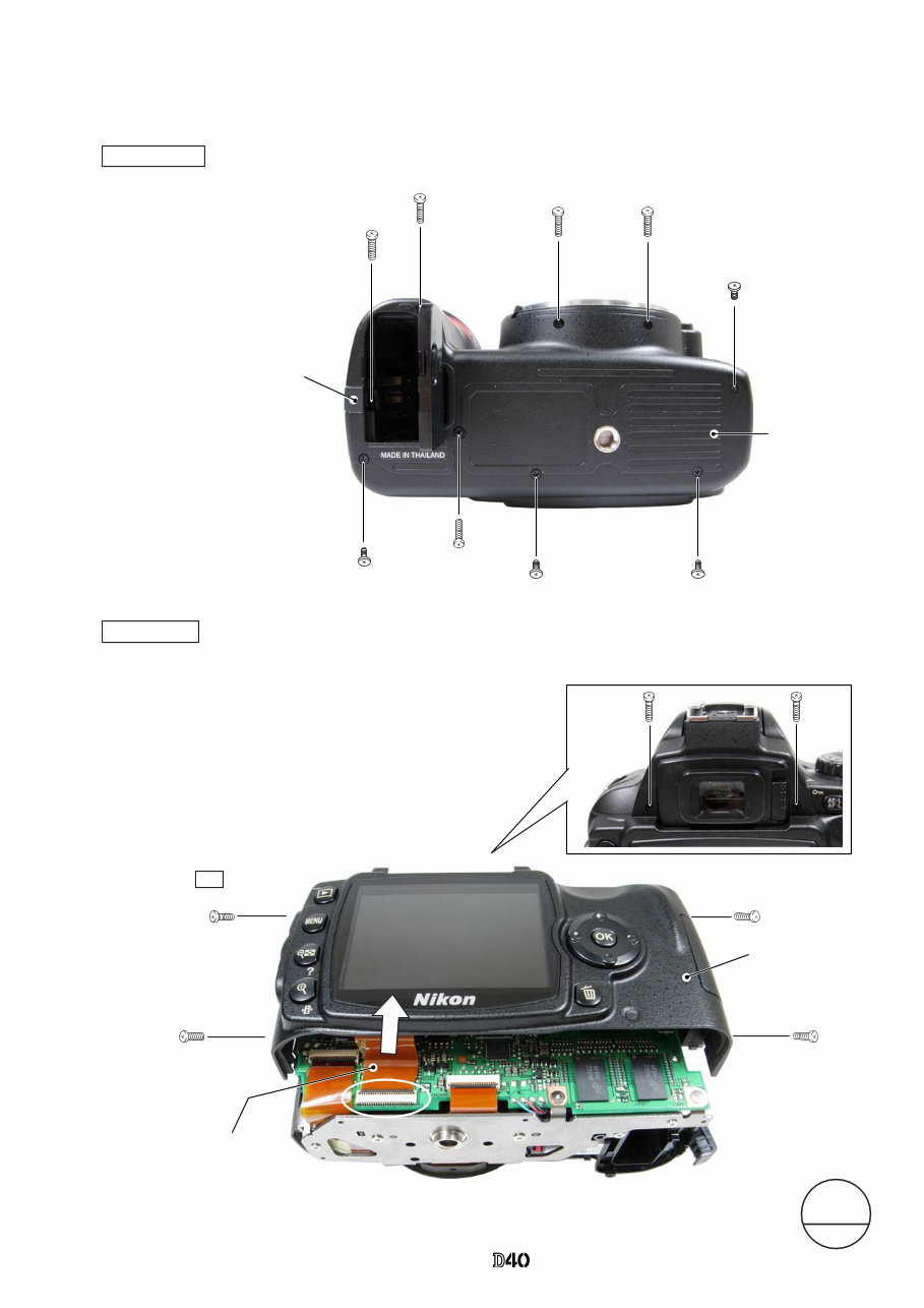
・Take out the four screws (#5690) and two screws (#5618).
・Remove the rear cover.
・ Take out the four screws (#5735)
and five screws (#5674).
・ Open the power-wire lid. Open the power-wire lid.
・ Remove the bottom cover.
#5735
#5674×2
#5735
#5674
#5674
#5735×2
#5674
・Remove the rear FPC from the connector.
Rear FPC
#5690×4
Rear cover
#5618×2
Power-wire lid
Disassembly
1. Separation of Front and Rear Bodies
Bottom Cover
Bottom cover
Rear cover
Note: Remove the rear cover slowly so as not to cut rear FPC of
the upper portion of the cover.
△ (Addition) NK
Changed page △×
M
サービス
計画課
Feb.05.2007
INC
- D・ -
VBA15001-R.3701.A
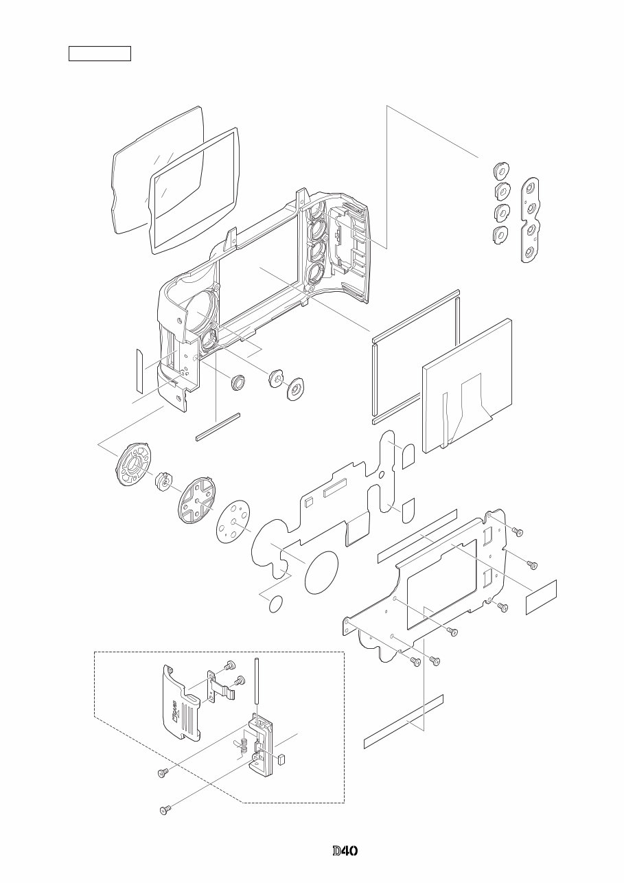
Rear cover
A
A
#402-3
#403
#5401-7
#5424-4
#5425-3
#5426-3
#5427-3
#421-2
#405×2
#1037
#5429-2
#423-2
#408
#5412-1
#5418-5
#413-1
#414
#1016-3
#453
#452
#451×2
#406-3
#750
#670×3
#630×3
#5431-1
#433
#5432-1
#404×2
#448
#407-2×2
#B5431
#5681×2
#753
INC
- D・ -
VBA15001-R.3701.A
#5610×2
#5610×2
#5074
#29-2
#26-2
#131
#626
#5120
#670
#B5024
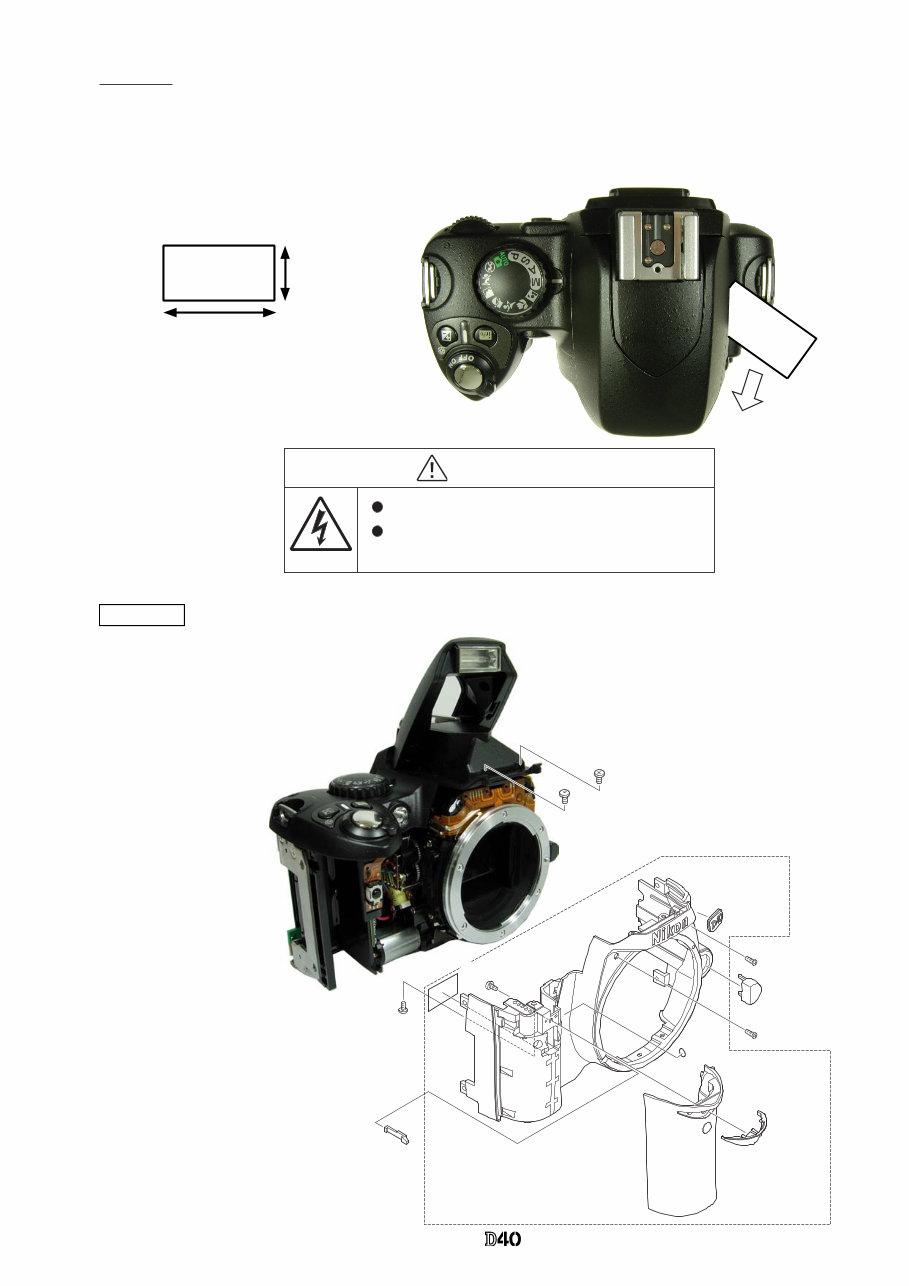
・Take out the four screws (#5610) and
the screw (#626).
・Remove the front cover unit (#B5024)
and [#131].
SB pop-up
・Cut the tracing film sheet, etc into the below size of piece.
Then insert it into the clearance of the top cover pop-up
part as shown right, and raise the SB by sliding the sheet in
the direction of the arrow.
Approx.2cm
Approx. 4cm
カバーを外した後は、修理指針の指示に従ってメインコンデン WARNING
Due to an internal high voltage area, take extra care not to get an
electric shock when detaching covers.
After removing the covers, be sure to discharge the main
condenser according to the instructions of repar manuals.
Covers
#750
#792C
INC
- D・ -
VBA15001-R.3701.A
Main
condenser
2KΩ/5W Be careful so that the top cover does NOT touch the
discharge tool.
Discharge of Main condenser
・Discharge the main condenser from its both ends.
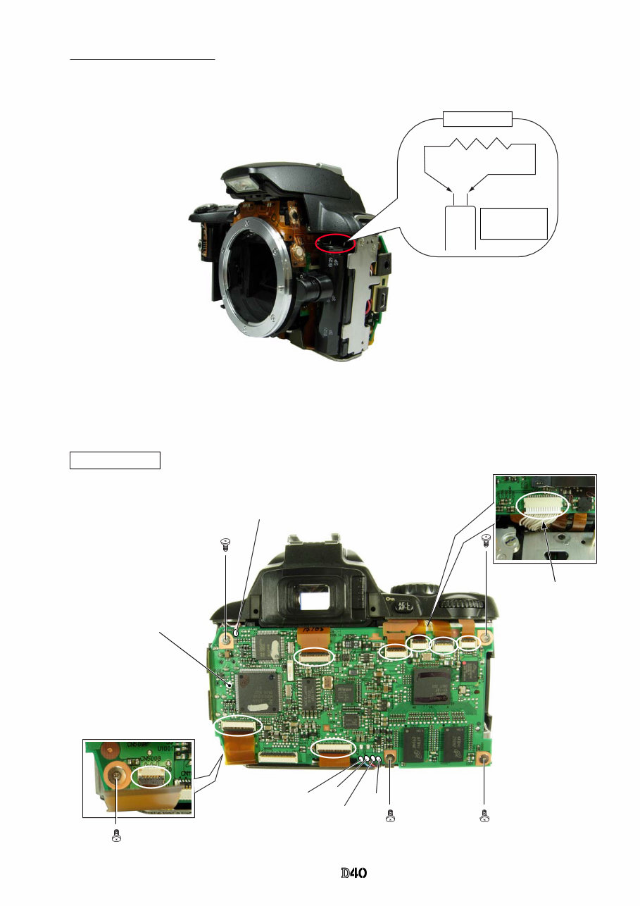
TOGO PCB (#B2001-1)
TOGO PCB unit
Gray
Red
Blue
Gray
Pink: Relay PCB
・ Disconnect the eight FPCs from the connector.
・ Unsolder the five wires.
・ Take out the five screws (#663).
・ Remove the harness.
・ Remove the TOGO PCB
(#B2001-1).
#663×5
Harness
TOGO PCB unit: Back
INC
- D・ -
VBA15001-R.3701.A
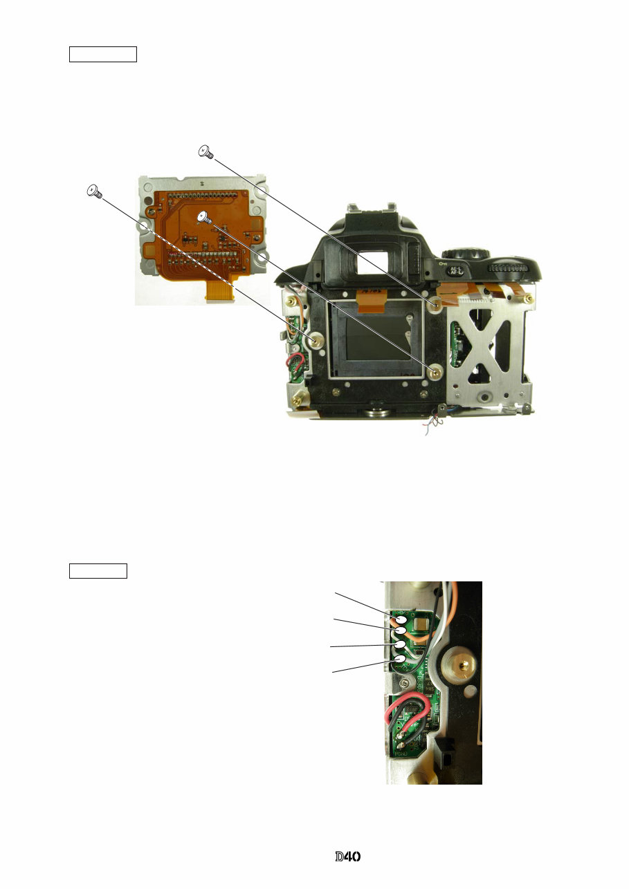
・ Take out the three screws (#631), and remove the CCD unit (#B3051-1).
CCD unit
Caution:
Some bodies have already washer(s) attached on
the mounting surface of CCD unit.
・ Unsolder the four wires (connected
from Top cover).
Orange: Top cover
White: Top cover
Gray: Top cover
Black: Top cover
SB PCB
#B3051-1
#631×3
INC
You're Reading a Preview
What's Included?
Fast Download Speeds
Online & Offline Access
Access PDF Contents & Bookmarks
Full Search Facility
Print one or all pages of your manual
$27.99
Viewed 18 Times Today


Secure transaction
What's Included?
Fast Download Speeds
Online & Offline Access
Access PDF Contents & Bookmarks
Full Search Facility
Print one or all pages of your manual
$27.99
The Nikon D40 Full Service Manual is an essential resource for professional mechanics and DIY enthusiasts alike. This comprehensive manual provides detailed technical information, diagrams, and instructions for servicing and repairing the Nikon D40 camera. Whether you're looking to troubleshoot issues or perform routine maintenance, this manual equips you with the knowledge needed to keep your camera in optimal condition.


