

Nikon D300 Camera Repair Service Manual
What's Included?
Fast Download Speeds
Online & Offline Access
Access PDF Contents & Bookmarks
Full Search Facility
Print one or all pages of your manual

作成承認印 配布許可印
VBA20001-R.3720.A
Copyright c 2007 by Nikon Corporation.
All Rights Reserved.
無断転載を禁ず !!
Printed in Japan NOV.2007
VBA20001
REPAIR MANUAL
M
サービス
計画課
INC
- D・ -
VBA20001-R.3720.A
Caution:
① In disassembly/(re)assembly, be sure to use conductive mat (J5033) and wrist strap (J5033-5), in
order to protect electric parts from static electricity.
② Before disassembling, be sure to remove batteries or AC power cord.
③ In disassembling, be sure to memorize the processing state of wires and FPC, screws to be fixed and
their types, etc.
④ The low-pass filter of the image PCB/base plate is easily damaged. Handle it very carefully.
⑤ is indicated in this manual when NK screw is used. Usually the same "NK" screw can be used
approx. up to three times. (NK screw = Loose-proofing screw to which the adhesive is already
applied and firmly fixed when screwed in.)
NK
Points to notice for Disassembly and Assembly
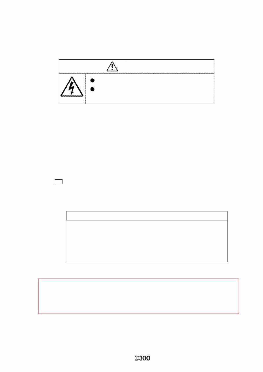
WARNING
Take extra care not to get an electric shock when detaching
covers.
After removing covers, be sure to discharge the main
condenser according to the instructions of repair manuals.
Caution:
When "Separation of Front body from Rear body", "Disassembly of CCD/FPC unit" and
"Disassembly of Bayonet" are performed, be sure to carry out "RESET AF-DEFOCUS
COMPENSATION" of the D300 adjustment software after assembly.
Points to notice for Lead-free solder products
・ Lead-free solder is used for this product.
・ For soldering work, the special solder and soldering iron are required.
・ Do NOT mix up lead-free solder with traditional solder.
・ Use the special soldering iron respectively for lead-free solder and lead solder.
They cannot be used in common.
INC
- D・ -
VBA20001-R.3720.A
#1647
#B60
#B447
#B63
#B61
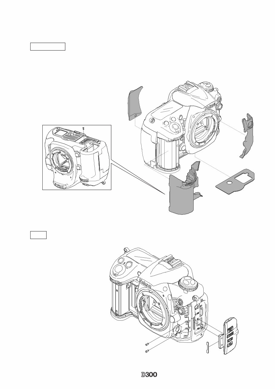
・ Remove the external rubber (#B60, #B61, #B63, and #B447).
#1642×2 #394
#392
IF lid
・Take out the two screws (#1642).
・Remove the IF lid (#392).
※ Caution: Take out the screw (#1647) first, and then remove the grip rubber (#B60).
Disassembly
1. External area and Image-related PCB/base plate
External rubber
INC
- D・ -
VBA20001-R.3720.A
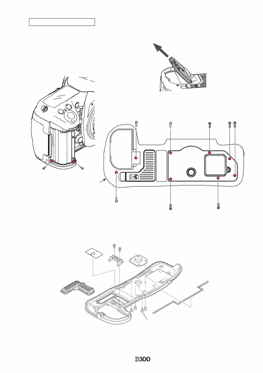
Bottom cover / Battery lid unit
・Open the battery lid (#B�01) approx. 4�-degree upwards, #B�01) approx. 4�-degree upwards, upwards,
and remove as if pulling it out.
・Take out the three screws (#1��0), five screws (#1��6), two
screws (#1509).
・Remove the bottom cover.
#1509×2
Battery cover (#B801)
#1571×2
#25
#807
#68
#1519×4
#806
#982
#981
#983
#1550
#1550
#1556
#1556
#1550
#1556
#1556
Bottom cover
INC
- D・ -
VBA20001-R.3720.A
Rear SW FPC, Retainer plate, and other small parts
#987
#923
#443
#923
#921
#1518×2
#442
#B423
#1628×2
#445
CF cover, sponge, other small parts
・Take out the two screws (#1518).
Rear cover unit
・Take out the two screws (#1553), two screws (#1547)
and one screw (#1551).
・Remove the rear cover slowly, and disconnect the three
FPCs from each connector.
#1551
#1547×2
#1553×2
#1020
#456
#B478
#1630
#1512×3
#422
#1625×3
#476
INC
- D・ -
VBA20001-R.3720.A
#465
#1511×2
#475
#426
#455
#962
#961
#924
#986
#985
#467
#1538×2
#469
#468
#481
#474
Selector button, Sponge, and other small parts
#431
#433
#488
#492
#487
#1627
#489
#1629
#1627×2
#484
#1546×2
#491
#1571
#486
#493
#434×2
#435×2
#1057
#432
#1626×3
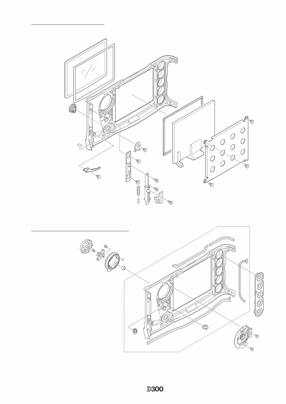
TFT monitor and other small parts
INC
- D・ -
VBA20001-R.3720.A
Soldering bridge
#1515
#1515
#1546×4
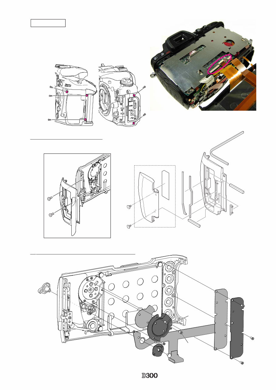
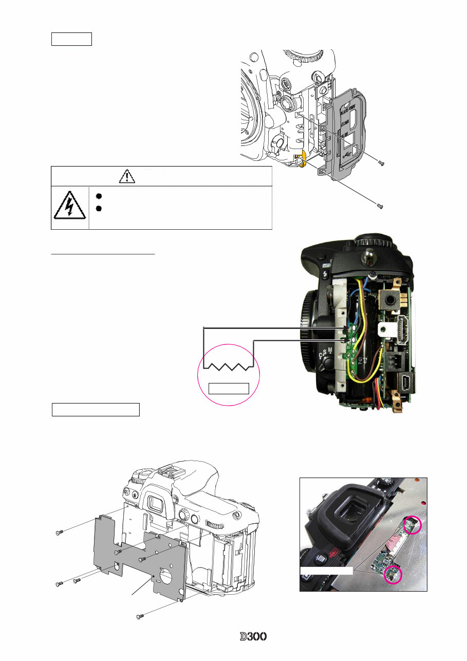
DG PCB shield plate
・Take out the four screws (#546) and two screws (#1515).
・Remove the two soldering bridges that joint DG-PCB and DG-PCB shield plate.
・Remove the DG-PCB shield plate.
#1510×2
I/F cover
・Take out the two screws (#1510) and remove
the I/F cover (#B28).
・Remove the conduct plate (#695).
#B28
#695
2KΩ/ 5W
Discharge of Main condenser
DG-PCB shield plate shield plate
WARNING
Take extra care not to get an electric shock when detaching
covers.
After removing covers, be sure to discharge the main
condenser according to the instructions of repair manuals.
INC
- D・ -
VBA20001-R.3720.A
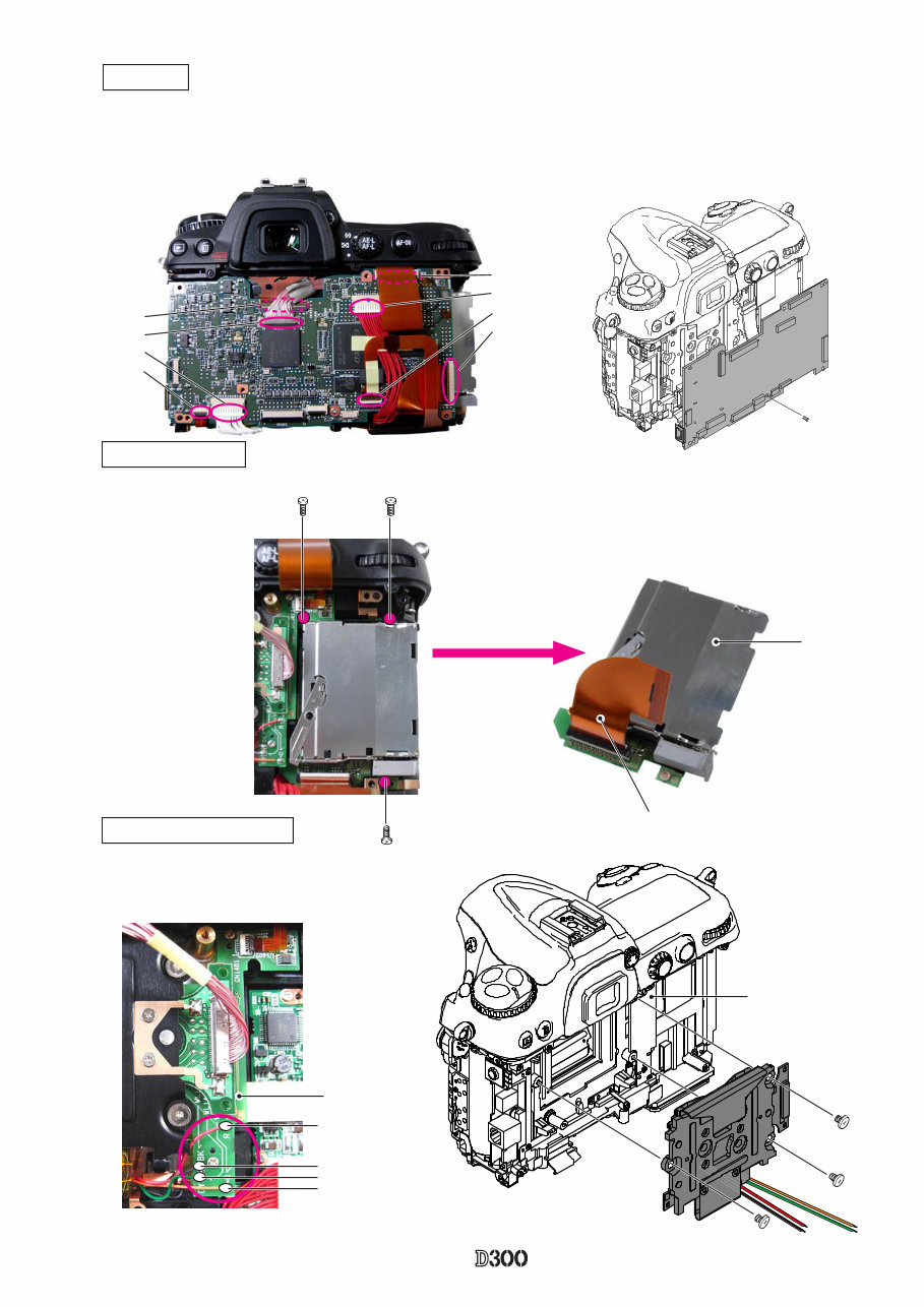
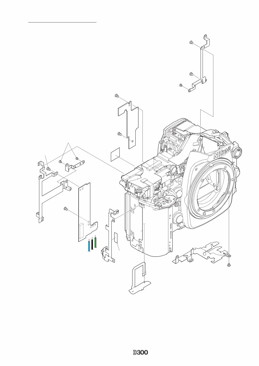
Image sensor holder unit
・Take out the three screws (#1543) and remove the CF base plate (#1018).
・Unsolder the DR base plate (#1014) at four places.
・Take out the three screws (#1639) and remove the
image sensor holder unit (#B10521).
#B10521
#1639×3
#1014
DG-PCB
・Remove the harnesses (#1075, #1074, and #1073) from each connector.
・Disconnect the FPC (#1027 #1027、#1040、#1041、#1039、#1038) from each connector. ) from each connector.
・Take out the screw (#1546) and remove [#B1017].
#B1017
#1546
#1041
#1075
#1073
#1040
#1039
#1074
#1027
#1038
CF base plate unit
#1543×3
Orange
Gray
Red
Black
DR base plate
#1018
#1038
INC
- D・ -
VBA20001-R.3720.A
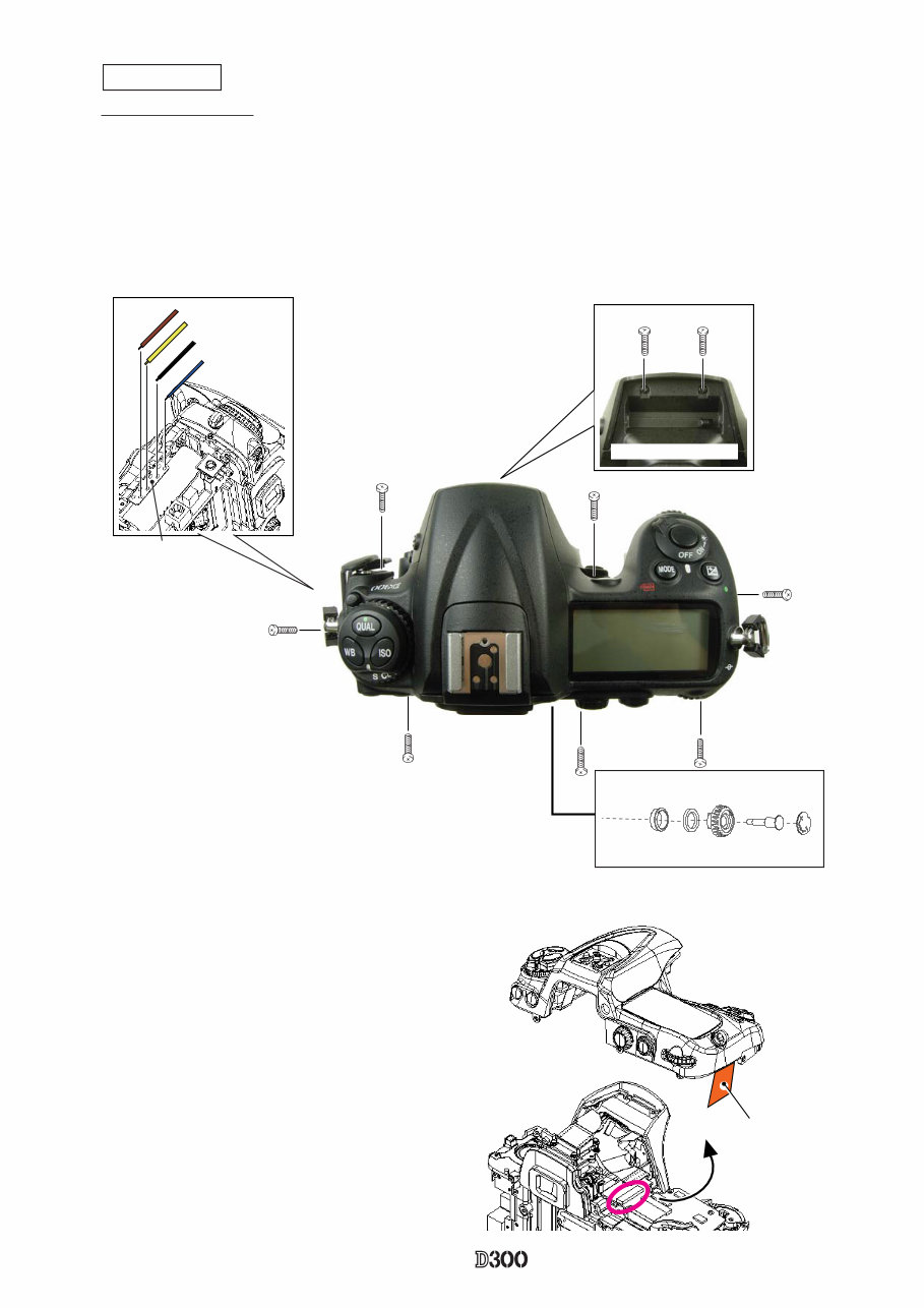
・Remove the dioptor-adjustment knob cover plate (#850), and take out the screw (#1622).
・Remove the dioptor-adjustment knob (#852), drip-proof sponge (#857) and drip-proof collar (#851).
・Raise the built-in speedlight, and take out the two screws (#1548), two screws (#1547), three screws (#1555)
and two screws (#1511).
・Remove the four solders of the DI base plate (#1029).
Top cover unit
Removal of Top cover
Connection-FPC
#1511×2
#1547×2 #1555
#1555
#1555
Raise (pop-up) here.
Dioptor adjustment knob
#851
#857
#852
#1622
#850
Brown
Yellow
Black
Blue
DI base plate
(#1029)
#1548×2
・Lift the top cover slowly so as not to cut the FPC, and disconnect the FPC
from the connector.
INC
- D・ -
VBA20001-R.3720.A
#1014
#1541×2
#811
#690
#1502
#1537×2
#1502×2
#1541
#1541
#691
#688
#769
#439
#1027
#B687
#15337
DR base plate and other small parts
INC
You're Reading a Preview
What's Included?
Fast Download Speeds
Online & Offline Access
Access PDF Contents & Bookmarks
Full Search Facility
Print one or all pages of your manual
$27.99
Viewed 80 Times Today


Secure transaction
What's Included?
Fast Download Speeds
Online & Offline Access
Access PDF Contents & Bookmarks
Full Search Facility
Print one or all pages of your manual
$27.99
This comprehensive manual provides 112 pages of service, maintenance, and repair guidance for the Nikon D300 camera. It includes step-by-step instructions and exploded views to facilitate quick and simple repairs. The manual is utilized by professional repair shops, offering significant cost savings compared to expensive professional repairs.
It covers all models and includes essential sections such as electrical and wiring. The manual's self-executing extractors reduce download time by nearly half, making it easily accessible for anyone. Each section is meticulously detailed, including disassembly, assembly/adjustment, and software, along with the necessary tools.
- Disassembly
- Separate Front and Rear Bodies
- Front Body
- Rear Body
- Assembly / Adjustment
- Front Body
- Mount Front Body on Rear Body
- Software
- Tools


