

NIKON COOLPIX S630 Service Repair Manual
What's Included?
Fast Download Speeds
Online & Offline Access
Access PDF Contents & Bookmarks
Full Search Facility
Print one or all pages of your manual

作成承認印 配布許可印
Copyright c 2009 by Nikon Corporation.
All Rights Reserved.
無断転載を禁ず !!
Printed in Japan February 2009
VMA41417-R.3779.A
VMA41417(BLACK)
VMA41007(SILVER)
VMA41117(RED)
VMA41217(BLUE)
VMA41317(PURPLE)
REPAIR MANUAL
M
サービス
計画課
INC

VMA41417-R.3779.A
- S630 -
Contents
Disassembly
Warning ・・・・・・・・・・・・・・・・・・・・・・・・・・・・・・・・・・・・・・・・・・・・・・・・・・・・・・・・・・・・・・・・・・・・・・・・・・・・・・・・・・・・・ D1
Caution for Disassembly/Assembly ・・・・・・・・・・・・・・・・・・・・・・・・・・・・・・・・・・・・・・・・・・・・・・・・・・・・・・・・・・・・・・・・ D2
External screws ・・・・・・・・・・・・・・・・・・・・・・・・・・・・・・・・・・・・・・・・・・・・・・・・・・・・・・・・・・・・・・・・・・・・・・・・・・・・・・・ D3
Rear cover ・・・・・・・・・・・・・・・・・・・・・・・・・・・・・・・・・・・・・・・・・・・・・・・・・・・・・・・・・・・・・・・・・・・・・・・・・・・・・・・・ D4-D5
Discharge of main condenser ・・・・・・・・・・・・・・・・・・・・・・・・・・・・・・・・・・・・・・・・・・・・・・・・・・・・・・・・・・・・・・・・・・・・・ D6
LCD unit・・・・・・・・・・・・・・・・・・・・・・・・・・・・・・・・・・・・・・・・・・・・・・・・・・・・・・・・・・・・・・・・・・・・・・・・・・・・・・・・・・・・・ D7
LCD holder・・・・・・・・・・・・・・・・・・・・・・・・・・・・・・・・・・・・・・・・・・・・・・・・・・・・・・・・・・・・・・・・・・・・・・・・・・・・・・・・・・・ D7
Strap holder ・・・・・・・・・・・・・・・・・・・・・・・・・・・・・・・・・・・・・・・・・・・・・・・・・・・・・・・・・・・・・・・・・・・・・・・・・・・・・・・・・・ D8
Battery cover ・・・・・・・・・・・・・・・・・・・・・・・・・・・・・・・・・・・・・・・・・・・・・・・・・・・・・・・・・・・・・・・・・・・・・・・・・・・・・・・・・ D8
Lens unit ・・・・・・・・・・・・・・・・・・・・・・・・・・・・・・・・・・・・・・・・・・・・・・・・・・・・・・・・・・・・・・・・・・・・・・・・・・・・・・・・・・ D8-D9
Decoration ring・・・・・・・・・・・・・・・・・・・・・・・・・・・・・・・・・・・・・・・・・・・・・・・・・・・・・・・・・・・・・・・・・・・・・・・・・・・・・・・ D10
DC cover ・・・・・・・・・・・・・・・・・・・・・・・・・・・・・・・・・・・・・・・・・・・・・・・・・・・・・・・・・・・・・・・・・・・・・・・・・・・・・・・・・・・ D11
Fromt cover ・・・・・・・・・・・・・・・・・・・・・・・・・・・・・・・・・・・・・・・・・・・・・・・・・・・・・・・・・・・・・・・・・・・・・・・・・・・・・・・・・ D11
Main PCB ・・・・・・・・・・・・・・・・・・・・・・・・・・・・・・・・・・・・・・・・・・・・・・・・・・・・・・・・・・・・・・・・・・・・・・・・・・・・・・・・・・・ D12
Speaker/Microphone ・・・・・・・・・・・・・・・・・・・・・・・・・・・・・・・・・・・・・・・・・・・・・・・・・・・・・・・・・・・・・・・・・・・・・・・・・・ D13
Condenser unit ・・・・・・・・・・・・・・・・・・・・・・・・・・・・・・・・・・・・・・・・・・・・・・・・・・・・・・・・・・・・・・・・・・・・・・・・・・・・・・・ D14
LED PCB ・・・・・・・・・・・・・・・・・・・・・・・・・・・・・・・・・・・・・・・・・・・・・・・・・・・・・・・・・・・・・・・・・・・・・・・・・・・・・・・・・・・ D15
Flash PCB・・・・・・・・・・・・・・・・・・・・・・・・・・・・・・・・・・・・・・・・・・・・・・・・・・・・・・・・・・・・・・・・・・・・・・・・・・・・・・・ D15-D16
Battery holder ・・・・・・・・・・・・・・・・・・・・・・・・・・・・・・・・・・・・・・・・・・・・・・・・・・・・・・・・・・・・・・・・・・・・・・・・・・・・ D16-D17
Battery lock lever ・・・・・・・・・・・・・・・・・・・・・・・・・・・・・・・・・・・・・・・・・・・・・・・・・・・・・・・・・・・・・・・・・・・・・・・・・・・・・ D18
USB cover ・・・・・・・・・・・・・・・・・・・・・・・・・・・・・・・・・・・・・・・・・・・・・・・・・・・・・・・・・・・・・・・・・・・・・・・・・・・・・・・・・・ D18
Flash unit ・・・・・・・・・・・・・・・・・・・・・・・・・・・・・・・・・・・・・・・・・・・・・・・・・・・・・・・・・・・・・・・・・・・・・・・・・・・・・・・ D18-D19
Tripod base ・・・・・・・・・・・・・・・・・・・・・・・・・・・・・・・・・・・・・・・・・・・・・・・・・・・・・・・・・・・・・・・・・・・・・・・・・・・・・・ D19-D20
Assembly
Tripod base ・・・・・・・・・・・・・・・・・・・・・・・・・・・・・・・・・・・・・・・・・・・・・・・・・・・・・・・・・・・・・・・・・・・・・・・・・・・・・・・・・・・ A1
Flash unit ・・・・・・・・・・・・・・・・・・・・・・・・・・・・・・・・・・・・・・・・・・・・・・・・・・・・・・・・・・・・・・・・・・・・・・・・・・・・・・・・・・・・ A2
USB cover ・・・・・・・・・・・・・・・・・・・・・・・・・・・・・・・・・・・・・・・・・・・・・・・・・・・・・・・・・・・・・・・・・・・・・・・・・・・・・・・・・・・ A3
Battery lock cover ・・・・・・・・・・・・・・・・・・・・・・・・・・・・・・・・・・・・・・・・・・・・・・・・・・・・・・・・・・・・・・・・・・・・・・・・・・・・・ A3
Battery holder ・・・・・・・・・・・・・・・・・・・・・・・・・・・・・・・・・・・・・・・・・・・・・・・・・・・・・・・・・・・・・・・・・・・・・・・・・・・・・・ A3-A5
Flash PCB・・・・・・・・・・・・・・・・・・・・・・・・・・・・・・・・・・・・・・・・・・・・・・・・・・・・・・・・・・・・・・・・・・・・・・・・・・・・・・・・・ A5-A6
LED PCB ・・・・・・・・・・・・・・・・・・・・・・・・・・・・・・・・・・・・・・・・・・・・・・・・・・・・・・・・・・・・・・・・・・・・・・・・・・・・・・・・・・・・ A6
Condenser unit ・・・・・・・・・・・・・・・・・・・・・・・・・・・・・・・・・・・・・・・・・・・・・・・・・・・・・・・・・・・・・・・・・・・・・・・・・・・・・・・・ A7
Speaker/Microphone ・・・・・・・・・・・・・・・・・・・・・・・・・・・・・・・・・・・・・・・・・・・・・・・・・・・・・・・・・・・・・・・・・・・・・・・・・・・ A8
Main PCB ・・・・・・・・・・・・・・・・・・・・・・・・・・・・・・・・・・・・・・・・・・・・・・・・・・・・・・・・・・・・・・・・・・・・・・・・・・・・・・・・・・・・ A9
LED window ・・・・・・・・・・・・・・・・・・・・・・・・・・・・・・・・・・・・・・・・・・・・・・・・・・・・・・・・・・・・・・・・・・・・・・・・・・・・・・・・ A10
Release button unit ・・・・・・・・・・・・・・・・・・・・・・・・・・・・・・・・・・・・・・・・・・・・・・・・・・・・・・・・・・・・・・・・・・・・・・・・・・・・ A10
Front cover ・・・・・・・・・・・・・・・・・・・・・・・・・・・・・・・・・・・・・・・・・・・・・・・・・・・・・・・・・・・・・・・・・・・・・・・・・・・・・・・・・・ A11
DC cover ・・・・・・・・・・・・・・・・・・・・・・・・・・・・・・・・・・・・・・・・・・・・・・・・・・・・・・・・・・・・・・・・・・・・・・・・・・・・・・・・・・・ A11
INC

VMA41417-R.3779.A
- S630 -
Decoration ring・・・・・・・・・・・・・・・・・・・・・・・・・・・・・・・・・・・・・・・・・・・・・・・・・・・・・・・・・・・・・・・・・・・・・・・・・・・ A11-A12
Caution: Contact of LENS VR UNIT ・・・・・・・・・・・・・・・・・・・・・・・・・・・・・・・・・・・・・・・・・・・・・・・・・・・・・・・・・・・・・ A12
Lens unit ・・・・・・・・・・・・・・・・・・・・・・・・・・・・・・・・・・・・・・・・・・・・・・・・・・・・・・・・・・・・・・・・・・・・・・・・・・・・・・・・ A13-A15
Battery cover ・・・・・・・・・・・・・・・・・・・・・・・・・・・・・・・・・・・・・・・・・・・・・・・・・・・・・・・・・・・・・・・・・・・・・・・・・・・・・・・・ A15
Strap holder ・・・・・・・・・・・・・・・・・・・・・・・・・・・・・・・・・・・・・・・・・・・・・・・・・・・・・・・・・・・・・・・・・・・・・・・・・・・・・・・・・ A15
LCD holder・・・・・・・・・・・・・・・・・・・・・・・・・・・・・・・・・・・・・・・・・・・・・・・・・・・・・・・・・・・・・・・・・・・・・・・・・・・・・・・・・・ A16
LCD unit・・・・・・・・・・・・・・・・・・・・・・・・・・・・・・・・・・・・・・・・・・・・・・・・・・・・・・・・・・・・・・・・・・・・・・・・・・・・・・・・・・・・ A17
Monitor cover ・・・・・・・・・・・・・・・・・・・・・・・・・・・・・・・・・・・・・・・・・・・・・・・・・・・・・・・・・・・・・・・・・・・・・・・・・・・・ A18-A19
Rear cover ・・・・・・・・・・・・・・・・・・・・・・・・・・・・・・・・・・・・・・・・・・・・・・・・・・・・・・・・・・・・・・・・・・・・・・・・・・・・・・ A19-A23
External screws ・・・・・・・・・・・・・・・・・・・・・・・・・・・・・・・・・・・・・・・・・・・・・・・・・・・・・・・・・・・・・・・・・・・・・・・・・・ A23-A24
Name plate ・・・・・・・・・・・・・・・・・・・・・・・・・・・・・・・・・・・・・・・・・・・・・・・・・・・・・・・・・・・・・・・・・・・・・・・・・・・・・・・・・・・ A24
Adjustment ・・・・・・・・・・・・・・・・・・・・・・・・・・・・・・・・・・・・・・・・・・・・・・・・・・・・・・・・・・・・・・・・・・・・・・・・・・・・・・・・・ A25-A42
Discription of circuit ・・・・・・・・・・・・・・・・・・・・・・・・・・・・・・・・・・・・・・・・・・・・・・・・・・・・・・・・・・・・・・・・・・・・・・・・・・・・ E1-E8
Electricity
Overall wiring ・・・・・・・・・・・・・・・・・・・・・・・・・・・・・・・・・・・・・・・・・・・・・・・・・・・・・・・・・・・・・・・・・・・・・・・・・・・・・・・・・E9
CP1(DMA)circuit diagram・・・・・・・・・・・・・・・・・・・・・・・・・・・・・・・・・・・・・・・・・・・・・・・・・・・・・・・・・・・・・・・・・・・・・・・E10
CP1(CAA)circuit diagram ・・・・・・・・・・・・・・・・・・・・・・・・・・・・・・・・・・・・・・・・・・・・・・・・・・・・・・・・・・・・・・・・・・・・・・・E11
CP2(PWA) circuit diagram ・・・・・・・・・・・・・・・・・・・・・・・・・・・・・・・・・・・・・・・・・・・・・・・・・・・・・・・・・・・・・・・・・・・・・・・E12
CP1(SYA)circuit diagram ・・・・・・・・・・・・・・・・・・・・・・・・・・・・・・・・・・・・・・・・・・・・・・・・・・・・・・・・・・・・・・・・・・・・・・・E13
ST1 circuit diagram ・・・・・・・・・・・・・・・・・・・・・・・・・・・・・・・・・・・・・・・・・・・・・・・・・・・・・・・・・・・・・・・・・・・・・・・・・・・・E14
ST2 circuit diagram ・・・・・・・・・・・・・・・・・・・・・・・・・・・・・・・・・・・・・・・・・・・・・・・・・・・・・・・・・・・・・・・・・・・・・・・・・・・・E15
TB1 circuit diagram ・・・・・・・・・・・・・・・・・・・・・・・・・・・・・・・・・・・・・・・・・・・・・・・・・・・・・・・・・・・・・・・・・・・・・・・・・・・・E16
CA1 circuit diagram ・・・・・・・・・・・・・・・・・・・・・・・・・・・・・・・・・・・・・・・・・・・・・・・・・・・・・・・・・・・・・・・・・・・・・・・・・・・・E17
Overall block diagram ・・・・・・・・・・・・・・・・・・・・・・・・・・・・・・・・・・・・・・・・・・・・・・・・・・・・・・・・・・・・・・・・・・・・・・・・・・E18
CCD block diagram ・・・・・・・・・・・・・・・・・・・・・・・・・・・・・・・・・・・・・・・・・・・・・・・・・・・・・・・・・・・・・・・・・・・・・・・・・・・・E19
Lens block diagram ・・・・・・・・・・・・・・・・・・・・・・・・・・・・・・・・・・・・・・・・・・・・・・・・・・・・・・・・・・・・・・・・・・・・・・・・・・・・E20
ASIC block diagram ・・・・・・・・・・・・・・・・・・・・・・・・・・・・・・・・・・・・・・・・・・・・・・・・・・・・・・・・・・・・・・・・・・・・・・・・・・・・E21
System control block diagram ・・・・・・・・・・・・・・・・・・・・・・・・・・・・・・・・・・・・・・・・・・・・・・・・・・・・・・・・・・・・・・・・・・・・E22
Power block diagram ・・・・・・・・・・・・・・・・・・・・・・・・・・・・・・・・・・・・・・・・・・・・・・・・・・・・・・・・・・・・・・・・・・・・・・・・・・・E23
Fuse arrangement ・・・・・・・・・・・・・・・・・・・・・・・・・・・・・・・・・・・・・・・・・・・・・・・・・・・・・・・・・・・・・・・・・・・・・・・・・・・・・・E24
Inspection standards ・・・・・・・・・・・・・・・・・・・・・・・・・・・・・・・・・・・・・・・・・・・・・・・・・・・・・・・・・・・・・・・・・・・・・・・・・・・ R1-R9
Tool list ・・・・・・・・・・・・・・・・・・・・・・・・・・・・・・・・・・・・・・・・・・・・・・・・・・・・・・・・・・・・・・・・・・・・・・・・・・・・・・・・・・・・・・・ T1-T2
Screw sheet・・・・・・・・・・・・・・・・・・・・・・・・・・・・・・・・・・・・・・・・・・・・・・・・・・・・・・・・・・・・・・・・・・・・・・・・・・・・・・・・・・・・・・・ S1
Changed Page △× 2
March.6.2009
△ (Revision)
Description
CP1(PWA) △ (Revision)
INC

VMA41417-R.3779.A
- D ・ S630 -
Disassembly
WARNING
There are high voltage parts inside. Be careful of this electric shock,
when you remove the cover.
You must discharge the main condenser according to the instruction
of this repair manual after you remove the cover.
!
Points to notice for Lead-free solder products
・Lead-free solder is used for this product.
・For soldering work, the special solder and soldering iron are required.
・Do not mix the lead-free solder with the conventional solder.
・Use the special soldering iron respectively for lead-free solder and lead solder. They cannot be used in
common.
Note : ① Before disassembling, remove the SD card and battery.
② When disassembling, make sure to memorize the processing state of wires, screws to be
fixed and their types, etc.
③ Because electrical parts are easily damaged by static electricity, make sure that you are
well earthed/grounded.
INC

VMA41417-R.3779.A
- D ・ S630 -
Caution for Disassembly/Assembly
This camera has VR function, so whenever the main PCB (CP-1) or lens unit is replaced, perform operations
based on the below flow chart.
Does main switch turn ON
Is it possible to "Get Current
(value)" by " SSIS_Cal"?
Replace main PCB. After
assembling all, input the
acquired "VR information"
manually.
Replace main PCB unit.
By using "SSIS_Cal", read "VR
information" from barcode which is
attached on lens unit, and write it by
"Set Current (value)" into main
PCB.
Adjust by "DSC_Cal".
After assembling all, write "VR
information" by "Set Current
(value)" of "SSIS_Cal" into main
PCB.
Yes
Yes
No
No
Process when main PCB is replaced Process when lens unit is replaced
Adjust by "SSIS_Cal".
By using "SSIS_Cal", read "VR
information" from barcode
which is attached on lens unit.
・SSIS_cal: SSIS calibration software (J65123)
・DSC_cal: calibration software (J65098)
INC
VMA41417-R.3779.A
- D3 ・ S630 -
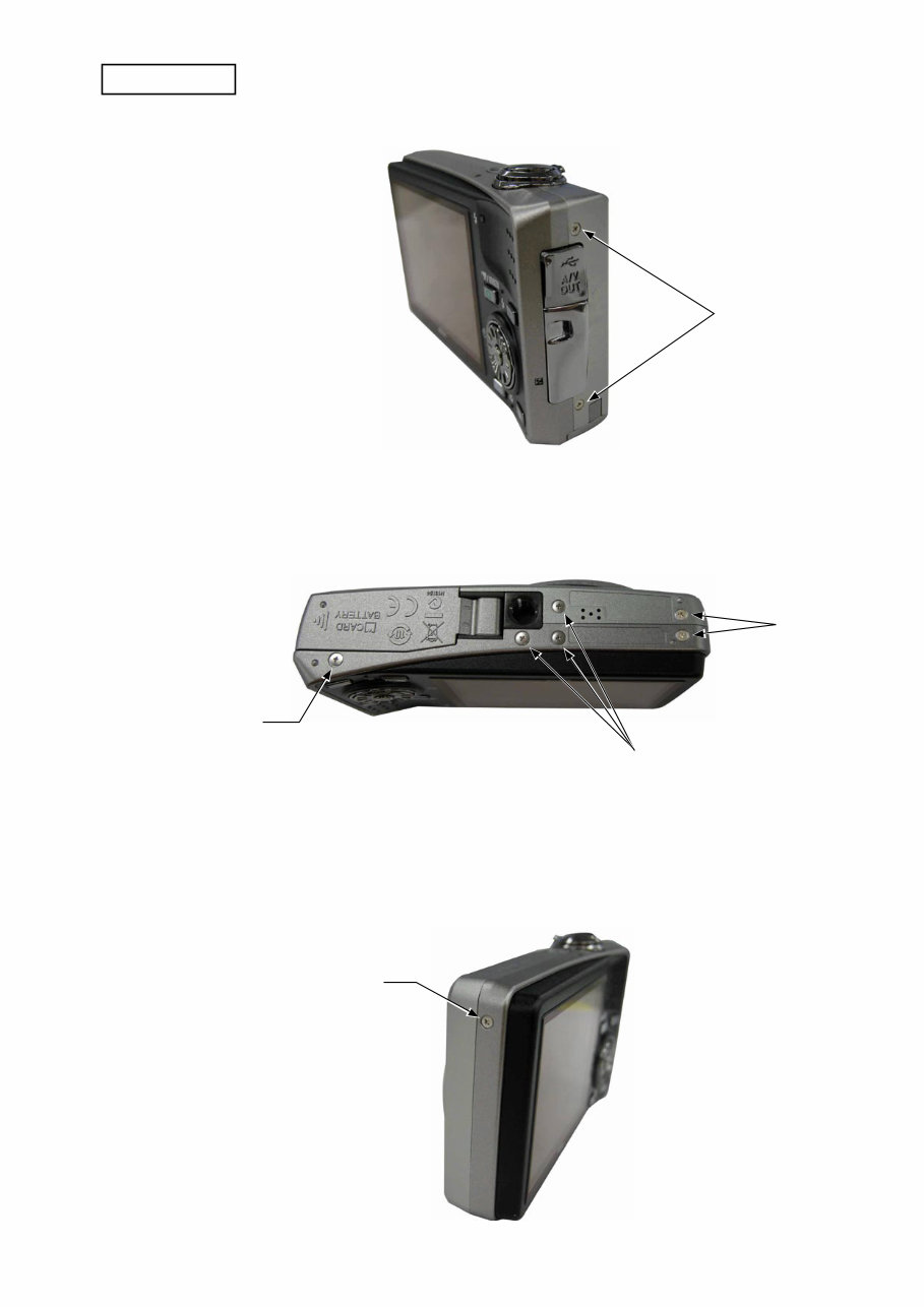
External screws
・ Take out the two screws (#102).
#102 × 2
・ Take out the four screws (#101).
・ Take out the two screws (#102).
#102 × 2
#101 × 3
#101
・ Take out the screw (#102).
#102
INC
VMA41417-R.3779.A
- D ・ S630 -
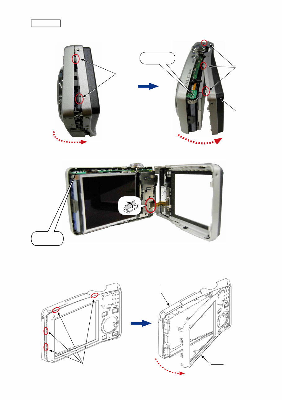
Unhook here.
Unhook here.
Rear cover
・ Remove the rear cover (#117) from the decoration cover (#115) by unhooking at four places.
#117
#115
・Disconnect the FPC.
・ Remove the rear cover (#101) by unhooking at five places.
Electric shock
hazard!
Electric shock
hazard!
Unhook here (Four places).
Rear cover unit
INC
VMA41417-R.3779.A
- D ・ S630 -
#114
#121
#118
#119
#114
#114
#120
#120
#122
#116
#117
#113
#114
#112
#115
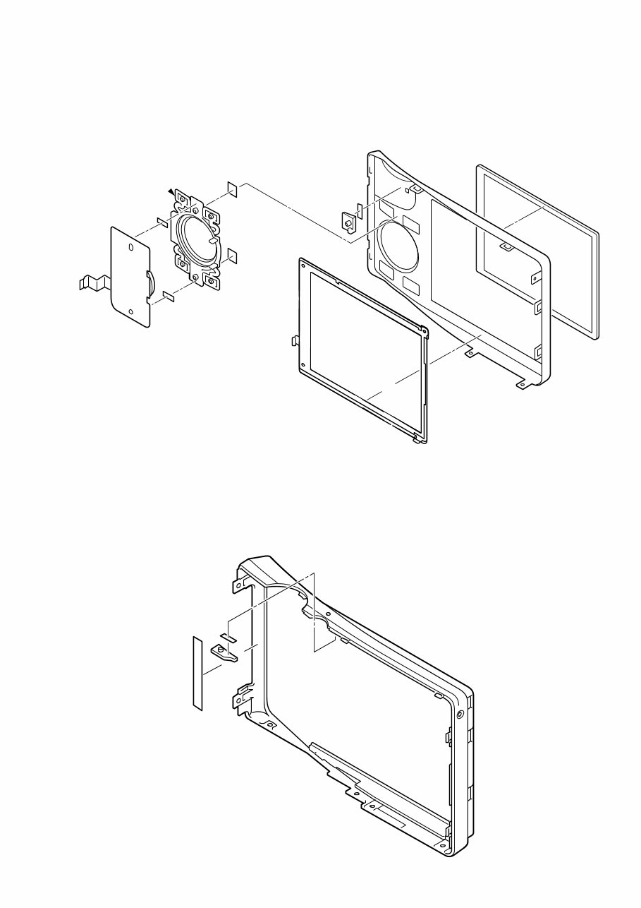
・ Peel off the monitor cover (#122) and the holder (#116).
・ Remove the control unit (#118).
・ Remove the control cover (#119).
・ Remove the LED window (#121).
・ Peel off the double stick tape (#112).
・ Remove the LED window (#113).
INC
VMA41417-R.3779.A
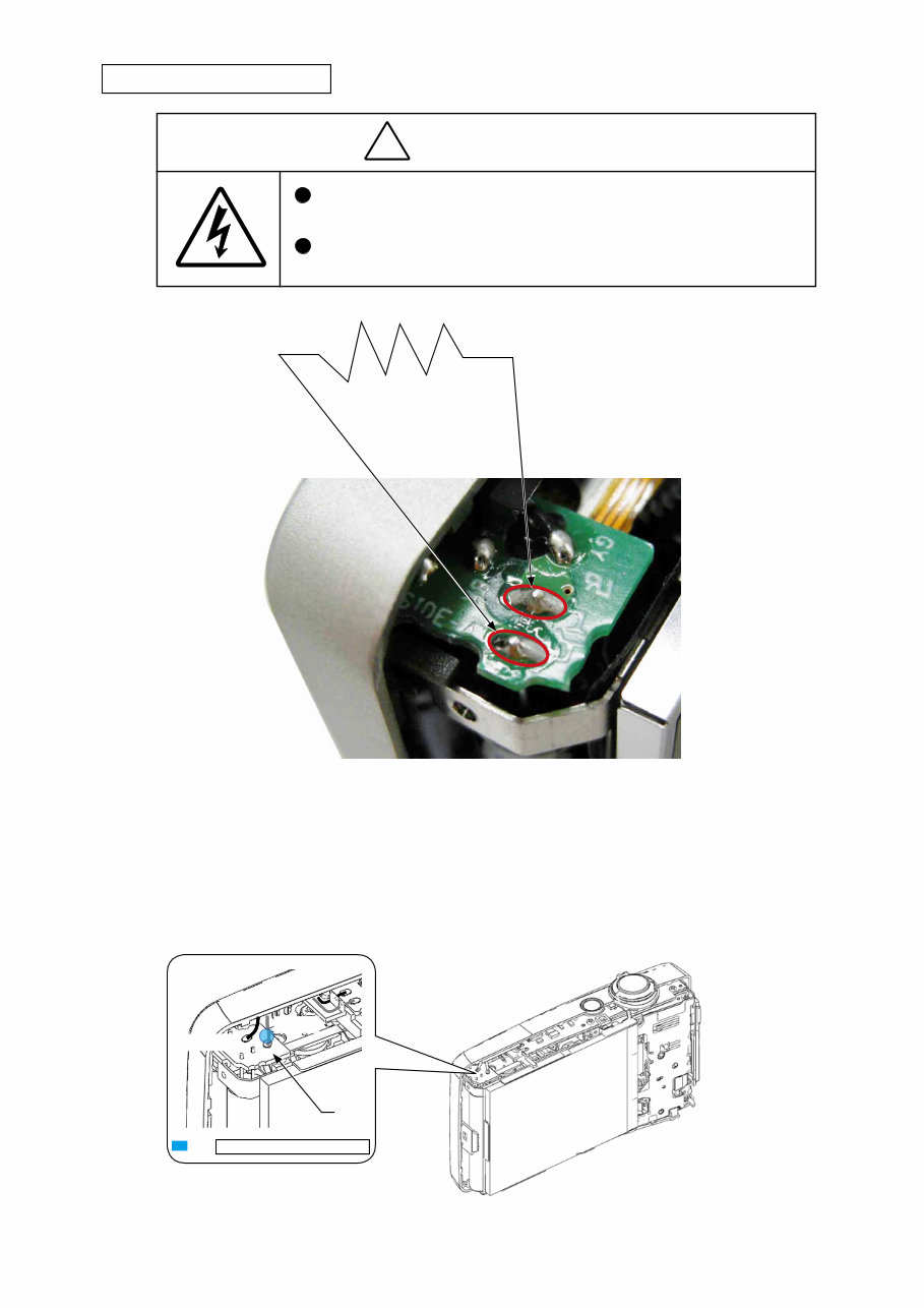
- D6 ・ S630 -
2K Ω /5W
・ Remove the adhesive C-8008B (BLACK) that bonds the wire (Gray) and condenser unit (#236).
area
[Gray]
[Black]
#236
Discharge of Main condenser
WARNING
There are high voltage parts inside. Be careful of this electric shock,
when you remove the cover.
You must discharge the main condenser according to the instruction
of this repair manual after you remove the cover.
!
Adhesive : C-8008B(BLACK)
INC
VMA41417-R.3779.A
- D・ S630 -
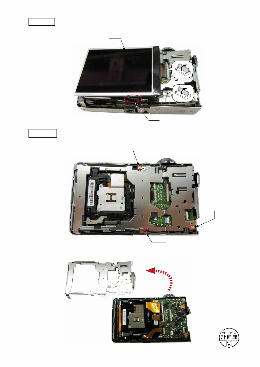
・ Take out the screw (#105).
・ Take out the two screws (#106).
#105
#106
#106
LCD holder
・ Disconnect the the two FPCs.
・ Remove the LCD unit (#111).
#111
LCD unit
Retainer plate
・ Remove the LCD holder (#19) from the camera body.
#19
Changed Page △× 1
March.6.2009
△ (Deletion)
INC
You're Reading a Preview
What's Included?
Fast Download Speeds
Online & Offline Access
Access PDF Contents & Bookmarks
Full Search Facility
Print one or all pages of your manual
$27.99
$36.99
Viewed 20 Times Today


Secure transaction
What's Included?
Fast Download Speeds
Online & Offline Access
Access PDF Contents & Bookmarks
Full Search Facility
Print one or all pages of your manual
$27.99
$36.99
This Service & Repair manual is an essential resource for both professional technicians and DIY enthusiasts. It provides detailed instructions for:
- Disassembly and reassembly
- Repair and upgrade
- Part replacement
- Service information
- Troubleshooting
- Software updating
- Adjustments and corrections
These manuals are fully illustrated with pictures and step-by-step instructions, making it easier to troubleshoot and repair your camera. All pages are printable, allowing you to have the necessary information at hand in your home, office, or repair shop.
Language: English
Format: PDF - Platform: Windows & MAC


