

p right b Nik n rp rati n
ll Rights Reser ed
載
Printed in Japan Februar
V R
R P R NU L
V

V R
CONTENTS
SPECIFICATIONS
Disassembly
WARNING
REAR COVER
DISASSEMBLY OF REAR COVER
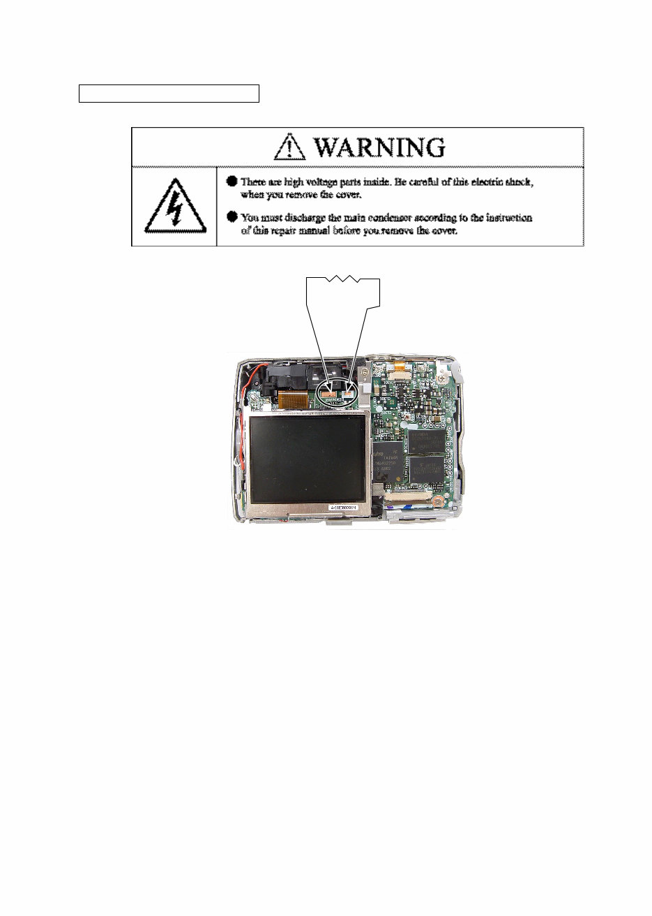
Discharging of main condenser
FRONT COVER
DISASSEMBLY OF FRONT COVER
TRIPOD SOCKET
LCD
SPEAKER HOLDER
MICROPHONE
MONITOR HOLDER
SB UNIT
WIRE HOLDER
TB-1 PCB
CONDENSER HOLDER
LENS UNIT
Points to notice when disassembling / (re)assembling Lens unit
Tools required for FFD inspection and adjustment
FINDER UNIT
ZOOM MOTOR UNIT
DISASSEMBLY OF ZOOM MOTOR UNIT
CCD FRAME
BARRIER UNIT
FIXED BARREL
DISASSEMBLY OF FIXED BARREL
2ND LENS GROUP UNIT
SHUTTER
STRAIGHT BARREL
KEY BARREL TURN BARREL
1ST LENS GROUP UNIT
ASSEMBLY
1ST LENS GROUP UNIT
KEY BARREL TURN BARREL
STRAIGHT BARREL
SHUTTER

V R
2ND LENS GROUP UNIT
ASSEMBLY OF FIXED BARREL
FIXED BARREL
CCD FRAME
ASSEMBLY OF ZOOM MOTOR UNIT
ZOOM MOTOR UNIT
FFD Inspection and adjustment (*FFD:Flange Focal Distance)
Preparation
FFD inspection and adjustment
FFD adjustment
BARRIER UNIT
Operation inspection
FINDER UNIT
Resolution inspection
LENS UNIT
CONDENSER HOLDER
TB-1 PCB
WIRE HOLDER
SB UNIT
MONITOR HOLDER
MICROPHONE
SPEAKER HOLDER
LCD
TRIPOD SOCKET
ASSEMBLY OF FRONT COVER
FRONT COVER
ASSEMBLY OF REAR COVER
REAR COVER
ADJUSTMENT
DISCRIPTION OF CIRCUIT
ELECTRICITY
OVERALL WIRING
CP1(DMA)CIRCUIT DIAGRAM
CP1(SYA) CIRCUIT DIAGRAM
CP1(CAA) CIRCUIT DIAGRAM
CP1(PWA) CIRCUIT DIAGRAM
CP1(STA) CIRCUIT DIAGRAM
ST1 CIRCUIT DIAGRAM

V R
TB1 CIRCUIT DIAGRAM
TB2 CIRCUIT DIAGRAM
OVERALL BLOCK DIAGRAM
CCD BLOCK DIAGRAM
LENS BLOCK DIAGRAM
ASIC BLOCK DIAGRAM
SYSTEM CONTROL BLOCK DIAGRAM
POWER BLOCK DIAGRAM
FUSE arrangement (CP1 PCB)
INSPECTION STANDARDS
Tool List

V R
M
Type E5600 digital camera
Effective pixels 5.1 million
CCD
Image size (pixels)
1/2.5 high-density CCD; total pixels: 5.36 million
2,592 1,944 (2592)
2,048 1,536 (2048)
1,024 768 (1024)
640 480 (640)
Lens
Focal length
f/-number
Construction
3 Zoom Nikkor
F=5.7 - 17.1 mm
(35-mm [135] camera-format equivalent: 35 - 105 mm)
f/2.9 - f/4.9
Seven elements in six groups
Digital zoom 4 (35-mm [135] camera-format equivalent:420 mm)
Autofocus (AF)
Focus range
Focus-area selection
Contrast-detect through the lens (TTL) AF
30 cm (1') - ; macro mode 4 cm/1.6 (M) -
Center with five-area selection in frame assist mode
Viewfinder
Magnification
Frame coverage
Real-image zoom viewfinder with LED indication
0.3 - 0.76
Approximately 82% horizontal and 82% vertical
Monitor
Frame coverage
(shooting mode)
1.8 , 80,000-dot, amorphous silicon TFT LCD monitor
Approximately 97% horizontal and 97% vertical
Storage Media
File system
File formats
Internal memory (14 MB)/SD memory cards
Compliant with Design Rule for Camera File System (DCF),
Exif 2.2, and Digital Print Order Format (DPOF)
Compressed: JPEG-baseline-compliant, Movies: QuickTime
Exposure
Metering
Exposure control
Range
256-segment matrix metering linked to AF area
(when frame is displayed in frame-assisted scene mode)
Programmed auto exposure with exposure compensation
(-2.0 - +2.0 EV in steps of 1/3 EV)
W: +1.1 - +17.1 EV, T: +2.6 - +18.6 EV
Shutter
Speed
Mechanical and charge-coupled electronic shutter
4 - 1/3,000 s
Aperture
Range
Electronically-controlled preset aperture
Two steps (f/2.9 and f/4.9 [W])
Sensitivity Approximately equivalent to ISO 50
(auto gain of two to four times) (up to equivalent of ISO 200)
Self-timer Ten-second duration
SPECIFICATIONS

V R
M
Built-in Speedlight
Range (approx.)
Flash control
W: 0.4 - 3.3 m/1'4 - 10'10
T: 0.4 - 2.0 m/1'4 - 6'7
Sensor flash system
Interface USB
Video output Can be selected from NTSC and PAL
I/O terminals A/V out/digital I/O
Power sources Two rechargeable Nikon EN-MH1 NiMH batteries
Two LR6 (AA) alkaline batteries
Two ZR6 (AA) nickel manganese batteries
Two FR6/L91 (AA) lithium batteries
EH-62B AC adapter
Number of frames taken in
succession
220 frames (alkaline batteries)
340 frames (EN-MH1)
600 frames (lithium batteries)
Measured at standard temperature (25 /77 F ) with fully charged batteries based on
CIPA standard: zoom adjusted with each shot, flash used in approximately one half of
shots, image type set to Normal.
Dimensions (W H D) 85 60 35 mm (3.3 2.4 1.3 )
Approximate weight 130 g (4.6 oz) without battery or memory card
Operating environment
Temperature
Humidity
0 - 40 (32 - 104 F )
Less than 85% (no condensation)

V R
Disassembly
Points to notice for Lead-free solder products
Lead-free solder is used for this product.
For soldering work, the special solder and soldering iron are required.
Do NOT mix up lead-free solder with traditional solder.
Use the special soldering iron respectively for lead-free solder and lead solder. They cannot
be used in common.
Note : Be sure to remove the SD memory card and batteries before disassembly.
When disassembling, make sure to memorize the processing state of wires, screws to be
fixed and their types, etc.
Because electrical parts are easily damaged by static electricity, make sure that you are
well earthed/grounded.
V R
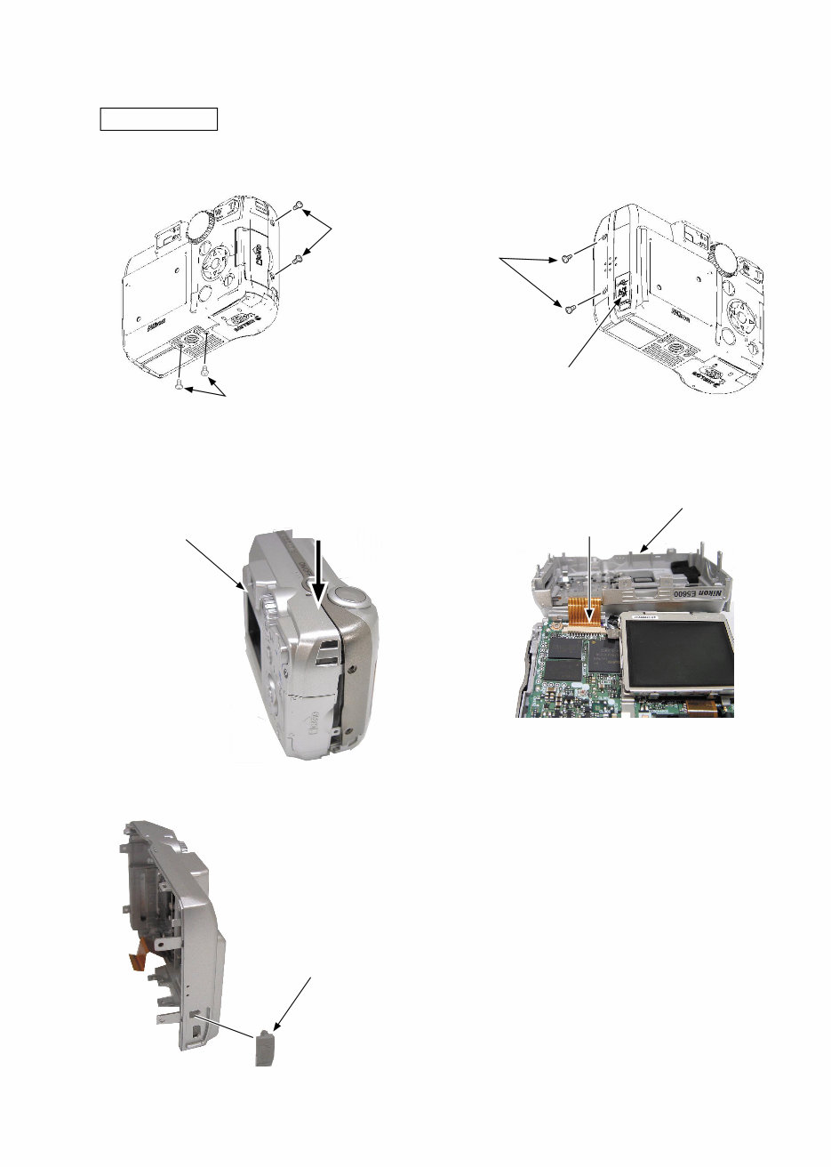
REAR COVER
Remove the four screws [#102]. Remove the two screws [#103].
Open the USB cover [#033].
As pushing the top side of the rear cover unit [#030]
by your finger, perform unhooking.
Open the rear cover unit [#030] slowly backward and
remove the FPC.
Remove the USB cover [#033].
Rear cover unit [#030]
FPC
Push.
Rear cover unit [#030]
Screw [#103]
USB cover [#033]
USB cover [#033]
Screw [#102]
Screw [#102]
V R
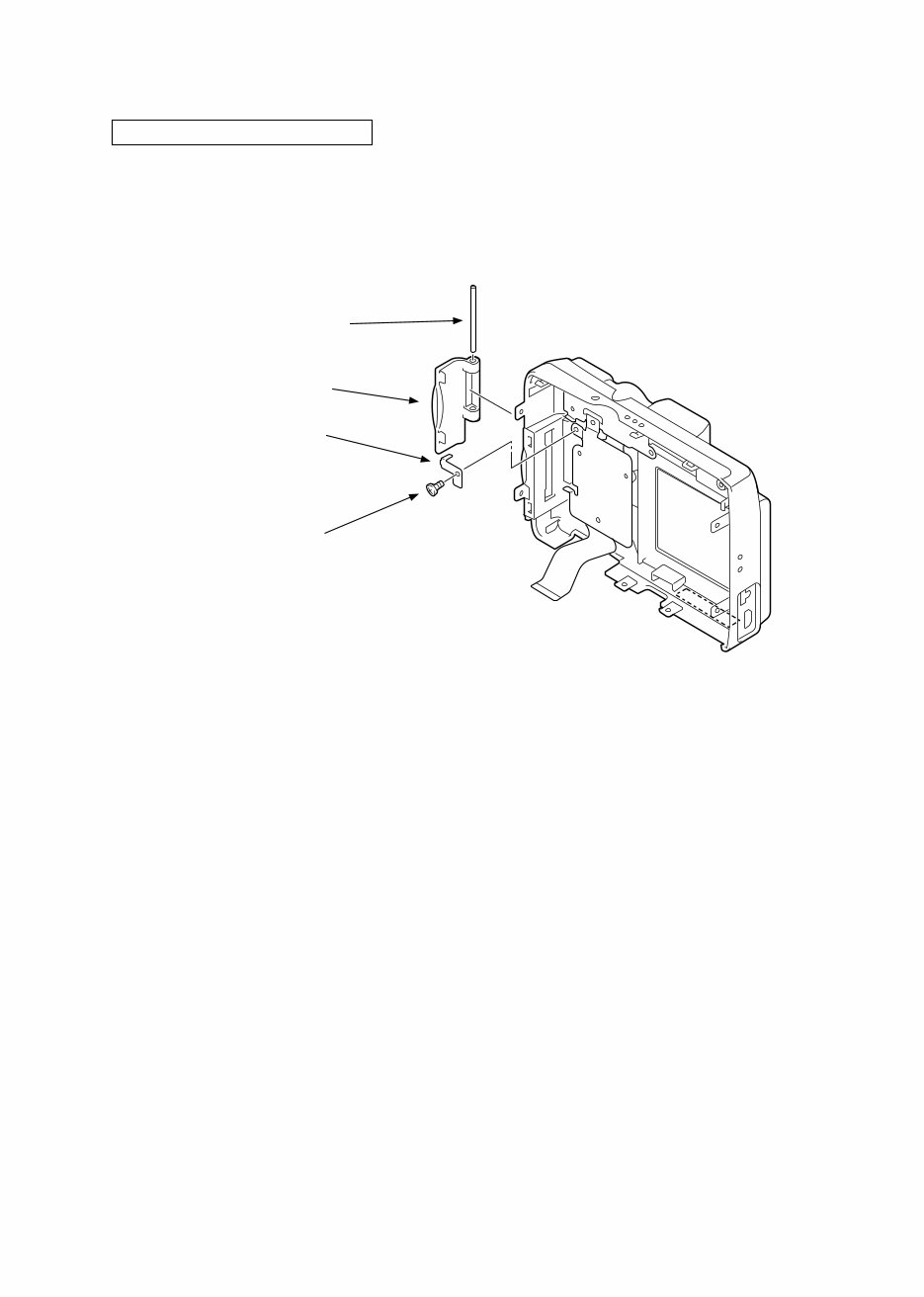
Remove the screw [#104].
Remove the earth shaft [#029].
Remove the cover shaft [#009].
Remove the SD cover [#037].
DISASSEMBLY OF REAR COVER
Earth shaft [#029]
Screw [#104]
SD cover [#037]
Cover shaft [#009]
V R
Discharging of main condenser
2KΩ/5W
You're Reading a Preview
What's Included?
 Lifetime Access
Fast Download Speeds
Online & Offline Access
Access PDF Contents & Bookmarks
Full Search Facility
Print one or all pages of your manual
$36.99
NIKON COOLPIX 5600 CAMERA Service Manual
Viewed 11 Times Today

What's Included?
Lifetime Access
Fast Download Speeds
Online & Offline Access
Access PDF Contents & Bookmarks
Full Search Facility
Print one or all pages of your manual
$36.99

Secure transaction
What's Included?
Lifetime Access
Fast Download Speeds
Online & Offline Access
Access PDF Contents & Bookmarks
Full Search Facility
Print one or all pages of your manual
Description
Fix your Nikon Coolpix 5600 yourself. This service manual covers disassembly, assembly, adjustment, circuit description, and electrical diagnostics with step-by-step photos and diagrams. 116 pages, all printable, works on any device.
Stop waiting for repairs. Download instantly, start working. Whether you need to replace a lens mechanism, troubleshoot power issues, or perform a full rebuild, you have the exact technical steps and parts breakdown right now. No shipping, no delays, no guessing.


