Fujifilm Fuji Finepix Z1 Service Manual & Repair Guide
What's Included?
Lifetime Access
Fast Download Speeds
Offline Viewing
Access Contents & Bookmarks
Full Search Facility
Print one or all pages of your manual
THE COMPONENTS IDENTIFIED WITH THE MARK “ ” ON THE SCHEMATIC DIAGRAM AND IN THE PARTS LIST ARE CRITICAL FOR SAFETY. PLEASE REPLACE ONLY WITH THE COMPONENTS SPECIFIED ON THE SCHEMATIC DIAGRAM AND IN THE PARTS LIST. IF YOU USE PARTS NOT SPECIFIED, IT MAY RESULT IN A FIRE AND AN ELECTRICAL SHOCK. FUJI PHOTO FILM CO., LTD. Ref.No.:ZM00596-102 Printed in Japan 2005.08 DIGITAL CAMERA FinePix Z1 US/CA/EU/EG/GE/ASCH/JP-Model SERVICE MANUAL WARNING BECAUSE THIS PRODUCTIS RoHS LEAD-FREE COMPLIANT, USE THE DESIG- NATED AFTER-SELES PARTS AND THE DESIGNATED LEAD-FREE SOLDER WHEN PERFORMING REPAIRS. (Refer to page 3 to page 6) CAUTION
2 FinePix Z1 Service Manual 7. CAUTION: FOR CONTINUED PROTECTION AGAINST FIRE HAZARD, REPLACE ONLY WITH SAME TYPE 2.5 AMPERES 125V FUSE. ATTENTION: AFIN D'ASSURER UNE PROTECTION PERMANENTE CONTRE LES RISQUES D'INCENDIE, REMPLACER UNIQUEMENT PAR UN FUSIBLE DE MEME, TYPE 2.5 AMPERES, 125 VOLTS. 8. WARNING: TO REDUCE THE ELECTRIC SHOCK, BE CAREFUL TO TOUCH THE PARTS. WARNING! HIGH VOLTAGE SAFETY CHECK-OUT After correcting the original problem, perform the following safety check before return the product to the customer. 1. Check the area of your repair for unsoldered or poorly soldered connections. Check the entire board surface for solder splasher and bridges. 2. Check the interboard wiring to ensure that no wires are “pinched” or contact high-wattage resistors. 3. Look for unauthorized replacement parts, particularly transistors, that were installed during a previous repair. Point them out to the customer and recommend their replacement. 4. Look for parts which, though functioning, show obvious signs of deterioration. Point them out to the customer and recommend their replacement. 5. Check the B + voltage to see it is at the values specified. 6. Make leakage - current measurements to determine that exposed parts are acceptably insulated from the supply circuit before returning the product to the customer. 2.5A 125V 2.5A 125V RISK OF FIRE- REPLACE FUSE AS MARKED
3 CONTENTS FinePix Z1 Service Manual Solder type Relative composition symbol Comments Sn96.5Ag3Cu0.5 A30C5 Displayed symbol: SnAgCu Sn99.3Cu0.7 C7 Sn89Zn8Bi3 Z80B30 Displayed symbol: SnZnBi Sn88In8Ag3.5Bi0.5 N80A35B5 If several different types of solder are used on a board (front or back), all types are shown. E.g.) A30C5/N80A35B5/C7 (front reflow/back reflow/back flow) RoHS lead-free compliance Because this product is RoHS lead-free compliant, use the designated after-sales parts and the designated lead-free solder when performing repairs. <Background & Overview> With the exception of parts and materials expressly excluded from the RoHS directive (*1), all the internal connections and component parts and materials used in this product are lead-free compliant (*2) under the European RoHS directive. *1: Excluded items (list of the main lead-related items) • Lead included in glass used in fluorescent tubes, electronic components and cathode-ray tubes • Lead in high-melting-point solder (i.e. tin-lead solder alloys that contain 85% lead or more) • Lead in ceramic electronic parts (piezo-electronic devices) • Mercury contained in fluorescent tubes is also excluded. *2: Definition of lead-free A lead content ratio of 0.1 wt% or less in the applicable locations (solder, terminals, electronic components, etc.) <Reference> RoHS: The name of a directive issued by the European Parliament aimed at restricting the use of certain designated hazardous substances included in electrical and electronic equipment. Designated substances (6): Lead, mercury, cadmium, hexavalent chromium, polybrominated biphenyls (PBBs) and polybrominated diphenyl ether (PBDE) <Display of lead-free compliance> Lead-free display on installed boards The icon shown below is screen-printed onto boards on which all the electronic components and solder have the lead-free status. (Pb: Lead; A30C5: Relative composition symbol for solder) Pb A30C5 •Relative composition of solder
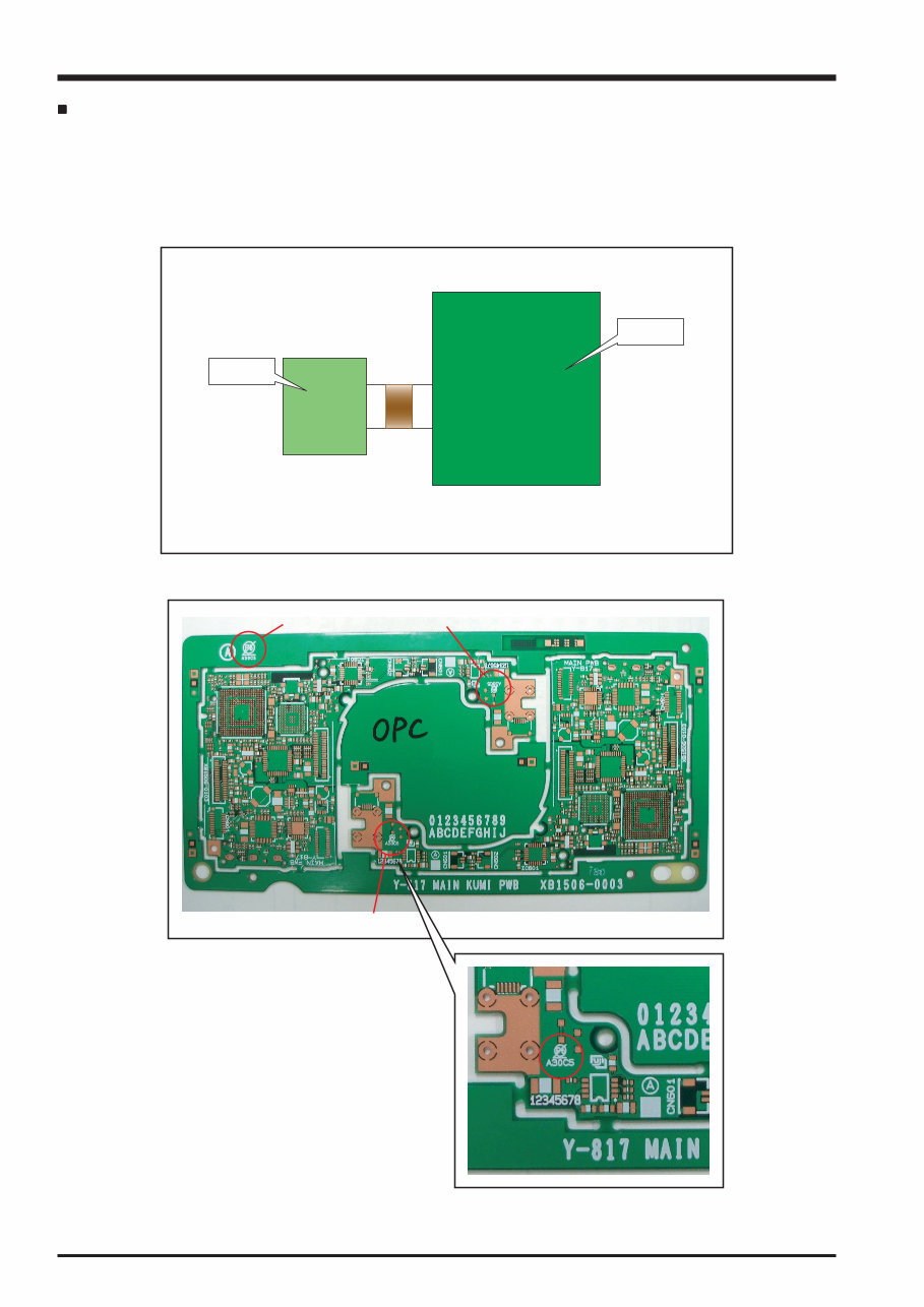
4 FinePix Z1 Service Manual CCD PWB MAIN PWB CN Indicated Indicated *3 *4 *4 Sample display locations Applicable boards: Displayed on boards with a total surface area of 10 cm 2 or more When a product contains multiple boards: • If solder connections are used between the boards, the indication is typically shown on the MAIN board. • When a board uses connectors, the indication is shown on each board. (See the figures below.) Sample configuration: Sample installed board (FinePix Z1) The icons are displayed on an unused section of the board (*3) and on a single substrate (*4). The display location differs from board to board but is shown in a readily visible position.
5 CONTENTS FinePix Z1 Service Manual Difference The solder starts melting later. Poor wetting Solder feed rate is difficult to control. Wetting the insides of through holes is especially difficult. During repairs (or modifications) removing solder from inside through holes is difficult. There is serious carbonization of the soldering iron. The surface is not glossy. 1 2 3 4 5 6 7 Countermeasure The initial melting point of lead-free solder is high, so you have to get used to it. Move the tip of the soldering iron around to heat the entire connection to the melting temperature and assist wetting. Use the solder (wire) diameter and soldering iron that are best suited to connection being soldered. First apply solder to the area immediately around the through hold and then feed the solder into the hole. Use a suitable wicking wire (with a suitable method and heating) and a suction tool. Either put solder onto the soldering iron tip after completing the work, or turn the iron off frequently. Learn to recognize the appearance of the surface. <Lead-free soldering> When carrying out repairs, use a designated lead-free solder, bearing in mind the differing work practices for conventional solder (eutectic) and lead-free solder. Differences in the soldering work for lead-free and eutectic solder When the soldering work practices for eutectic solder and lead-free solder are compared, the main differences are as shown below. In particular, when lead-free solder is used, the solder tends to be less workable than when eutectic solder is used. Accordingly, the soldering techniques used must take that into account. Setting temperature during lead-free soldering • Lead-free solder melting temperature The melting point of eutectic (Sn-Pb) solder is 183°C, while the melting point of lead-free solder (Sn-Ag-Cu) is 30°C higher at 220°C. • Soldering iron tip temperature The temperature setting for the soldering iron used should be such that the tip of the soldering iron is at the correct bonding temperature for the connection. This temperature is normally set at around 100°C higher than the melting point of the solder. However, the actual temperature should take into account the shape and size of the soldering iron tip, the heat tolerance of the connection and the workability of that temperature. • Correct bonding temperature The correct bonding temperature refers not to the temperature of the heat source, but to the bonding temperature that will give the best bond strength. Precautions when soldering with lead-free solder • Soldering iron maintenance Because of the high soldering iron temperature in lead-free soldering, there is rapid carbonization of the flux adhering to the tip of the soldering iron. (1) Always cover the tip of the soldering iron with solder when it is not being used. (2) If the tip is black from carbonization, wipe it gently with a paper towel soaked in alcohol until the solder will wet. • Uniform heating of the board and components To ensure that the lead-free solder wets the entire surface of the pattern and the lands despite its poor wetting characteristics, you must move the tip of the soldering iron over a wide area to raise the temperature of the entire connection.
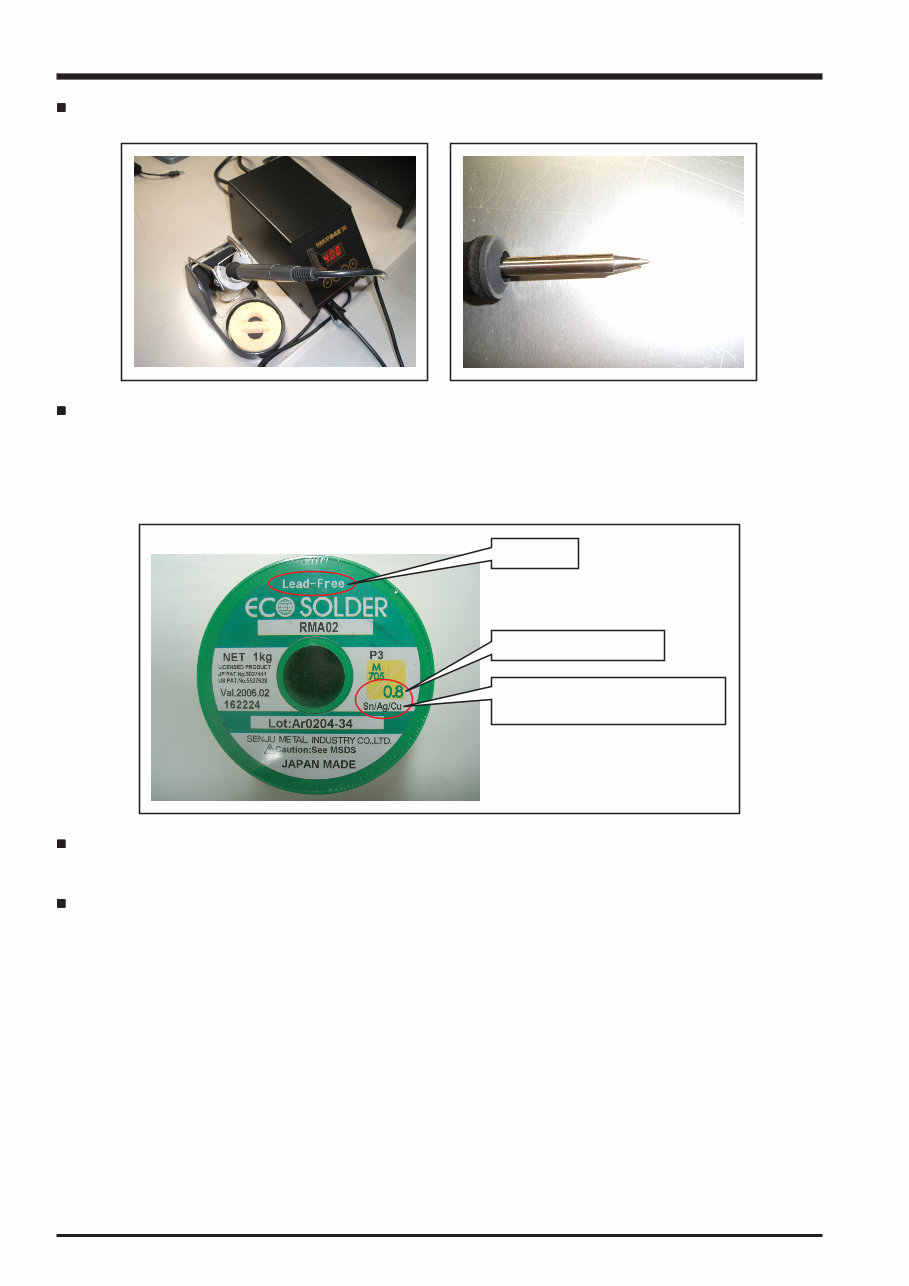
6 FinePix Z1 Service Manual lead-free Wire diameter 0.8mm Solder type (Displayed symbol) SnAgCu Soldering iron A soldering iron with a temperature control is best. Solder wire (thread) Use the lead-free solders specified below. Solder type: Sn96.5Ag3Cu0.5 (Displayed symbol: SnAgCu) Wire diameter: 0.6, 0.8 or 1.0 mm Sample: Flux Conventional flux can be used. Solder application wires (mesh, wicking wire, etc.) Conventional application wires can be used.
7 CONTENTS FinePix Z1 Service Manual CONTENTS 1. General ........................................................... 8 1-1. Product specification .............................................. 8 1-2. Explanation of Terms ............................................ 11 1-3. Names of External Components .......................... 12 2. Disassembly ................................................. 13 2-1. Names of internal Components ............................ 13 2-2. Removing the FRONT MAIN ASSY ..................... 14 2-3. Removing the INNER BLOCK .............................. 15 2-4. Removing the microphone and INNER CABI R ..... 16 2-5. Removing the LCD CONST ................................. 17 2-6. Removing the LENS ASSY .................................. 18 2-7. Removing the ST CONST .................................... 19 2-8. Removing the BATTERY HOLDER ...................... 20 2-9. Removing the BARRIER ASSY ............................ 21 2-10. Removing the KEY UNIT ...................................... 22 3. Schematics ................................................... 23 3-1. Cautions ............................................................... 23 3-2. Basic Block Names and Functions ....................... 23 3-3. Description of Main Block Functions .................... 24 3-3-1. Technical Overview ................................. 24 3-4. Block Diagram ...................................................... 25 3-5. Overall connection Diagram ................................. 26 3-6. Circuit Diagrams ................................................... 27 3-6-1. CAMERA BLOCK ................................... 27 3-6-2. MOTOR BLOCK ..................................... 28 3-6-3. PROCESS BLOCK ................................. 29 3-6-4. DCDC BLOCK ........................................ 30 3-6-5. IPST BLOCK ........................................... 31 3-6-6. LCD BLOCK ........................................... 32 3-6-7. KEY BLOCK ........................................... 33 3-6-8. CHG BLOCK ........................................... 35 3-6-9. AUDIO BLOCK ....................................... 36 3-6-10. MEDIA BLOCK ....................................... 37 3-6-11. VIDEO BLOCK ....................................... 37 3-6-12. MULTI BLOCK ........................................ 38 3-6-13. CCD FPC BLOCK ................................... 39 3-7. Mounted Parts Diagrams ...................................... 40 3-7-1. MAIN PWB ASSY ................................... 40 4. Adjustments .................................................. 42 4-1. Important point Adjustment when Replacing Major Parts .......................................... 42 4-2. Measuring Instruments Used ............................... 42 4-3. Use Jig list ............................................................ 42 4-4. Calibration method of pattern box ........................ 43 4-5. Adjusting soft installation ...................................... 43 4-5-1. Various downloading software decompressions, preservation methods, and notes ................................................ 43 4-5-2. Installation of DSC jig driver ................... 44 4-5-3. Adjusting soft initiation method ............... 44 4-6. Initial Settings of the Adjustment Software ........... 45 4-7. Starting the Adjustment Software ......................... 48 4-8. [R] : Flash Memory Reset ..................................... 51 4-9. [F4] : CCD Data Input ........................................... 53 4-10. [F5] : CAMERA Adjustment .................................. 55 4-11. [F6] : AF Adjustment ............................................. 59 4-12. [F7] : Flash Adjustment ......................................... 62 4-13. [F1] : Battery Voltage Adjustment ......................... 64 4-14. [F11] : Video Adjustment ...................................... 68 4-15. [F8] : Firmware Download .................................... 70 4-16. [F12] : End Setting ................................................ 72 5. Inspection ..................................................... 76 5-1. Required Measuring Equipment ........................... 76 5-2. Connection of Measuring Equipment ................... 76 5-3. Inspection and Factory Settings ........................... 77 6. Parts List ....................................................... 79 6-1. Silver Model .......................................................... 79 6-1-1. Packing and Accessories ........................ 79 6-1-1-1. US-model ................................. 79 6-1-1-2. CA-model ................................. 80 6-1-1-3. EU-model ................................. 81 6-1-1-4. EG-model ................................. 82 6-1-1-5. GE-model ................................. 83 6-1-1-6. AS-model ................................. 84 6-1-1-7. CH-model ................................. 85 6-1-1-8. JP-model .................................. 86 6-1-2. Mecha Block ........................................... 87 6-1-2-1. US/CA/EU/EG/GE/AS/CH-Model ... 87 6-1-2-2. JP-Model .................................. 88 6-2. Black Model .......................................................... 89 6-2-1. Packing and Accessories ........................ 89 6-2-1-1. US-model ................................. 89 6-2-1-2. CA-model ................................. 90 6-2-1-3. EU-model ................................. 91 6-2-1-4. EG-model ................................. 92 6-2-1-5. GE-model ................................. 93 6-2-1-6. AS-model ................................. 94 6-2-1-7. CH-model ................................. 95 6-2-1-8. JP-model .................................. 96 6-2-2. Mecha Block ........................................... 97 6-2-2-1. US/CA/EU/EG/GE/AS/CH-Model ... 97 6-2-2-2. JP-Model .................................. 98 6-3. Red Model (JP-Model only) .................................. 99 6-3-1. Packing and Accessories ........................ 99 6-3-2. Mecha Block ......................................... 101 6-4. Blue Model (JP-Model only) ............................... 103 6-4-1. Packing and Accessories ...................... 103 6-4-2. Mecha Block ......................................... 105 6-5. Electrical parts .................................................... 107 7. Appendix ..................................................... 108 7-1. List of Related Technical Updates Issued .......... 108
8 1. General FinePix Z1 Service Manual 1. General 1-1. Product specification System Model Digital camera FinePix Z1 Effective pixels 5.1 million pixels CCD 1/2.5-inch Super CCD HR Number of total pixels: 5.22 million pixels Storage media xD-Picture Card (16/32/64/128/256/512 MB/1 GB) File format Still image: DCF-compliant Compressed: Exif ver.2.2 JPEG, DPOF-compatible * Design rule for Camera File System compliant DPOF compatible Movie: AVI format, Motion JPEG Audio: WAVE format, Monaural sound Number of recorded pixels Still image: 2592 × 1944 pixels/2736 × 1824 pixels/2048 × 1536 pixels/ 1600 × 1200 pixels/640 × 480 pixels ( / / / / ) Lens Fujinon 3× optical zoom lens F3.5-F4.2 Focal length f=6.1 mm-18.3 mm (Equivalent to approx. 36 mm-108 mm on a 35 mm camera) ( : Equivalent to approx. 38 mm-114 mm on a 35 mm camera) Digital zoom Approx. 5.7× (3× optical zoom lens is used together: Max. zoom scale: 17.1×) Aperture (Wide-angle) F3.5/F5/F8 3 steps Focal range Normal: approx. 60 cm (2.0 ft.) to infinity Macro: approx. 8 cm (3.1 in.) to 80 cm (2.6 ft.) (wide-angle) approx. 45 cm (1.5 ft.) to 80 cm (2.6 ft.) (telephoto) Sensitivity AUTO/Equivalent to ISO 64/100/200/400/800 Photometry TTL 64-zones metering Exposure control Program AE Scene position (NATURAL LIGHT), (PORTRAIT), (LANDSCAPE), (SPORT), (NIGHT) Exposure compensation -2 EV to +2 EV in 1/3 EV-step increments ( ) Shutter speed 4 sec. to 1/1000 sec. (depend on Exposure mode) Focus Mode: Auto focus AF system: TTL contrast-type AF frame selection: AF (CENTER), AF (MULTI) White balance Automatic scene recognition/Preset (Fine, Shade, Fluorescent (Daylight), Fluorescent (Warm White), Fluorescent (Cool White), Incandescent) Self-timer Approx. 10 sec./2 sec. Flash type Auto flash Effective range (AUTO): Wide-angle: approx. 30 cm-3 m (1.0 ft.-9.8 ft.) Telephoto: approx. 60 cm-2.3 m (2.0 ft.-7.5 ft.) Flash mode Auto, Red-Eye Reduction, Forced Flash, Suppressed Flash, Slow Synchro, Red-Eye Reduction + Slow Synchro LCD monitor 2.5 inches, Aspect ratio: 4:3; approx. 115,000 pixels Amorphous silicon TFT, Approx. 100% coverage Movie 640 × 480 pixels/320 × 240 pixels ( / ) (30 frames per second with monaural sound) A series of continuous image can be recorded up to available recording time per xD-Picture Card. Zoom cannot be used during movie recording.
9 1. General FinePix Z1 Service Manual System Photography functions High-speed shooting, Best framing, Post shot assist window, Frame No. memory Playback functions Trimming, Image rotate, Automatic playback, Multi-frame playback, Sorting by date, Voice memo Other functions PictBridge, Exif print, PRINT Image Matching II, Language (English, Francais, Deutsch, , Italiano, , ), World time (Time difference), FinePix photo mode ( -mode) Input/Output Terminals A/V OUT NTSC/PAL-type (with monaural sound, connection via cradle) (Audio/Visual output) Digital input/output USB2.0 High-Speed (connection via cradle) DC input socket AC Power Adapter AC-5VW (included)/AC-5VX (sold separately) (connection via cradle) Power Supply and Others Power supply Use one of the following • Rechargeable Battery NP-40 According to the CIPA (Camera & Imaging Products Association) standard procedure for measuring digital still camera battery consumption (extract): When using a battery, use the battery supplied with the camera. The storage media should be xD-Picture Card. Pictures should be taken at a temperature of +23 o C (+73 o F), with the LCD monitor turned on, the optical zoom moved from full wide-angle to full telephoto (or vice-versa) and back again to its original position every 30 seconds, the flash used at full power every second shot and the camera turned off and then on again once every 10 shots. • Note: As the number of available shots varies depending on the level of charge in battery, the figures shown here for the number of available shots using battery is not guaranteed. The number of available shots will also decline at low tempera- tures. Camera dimensions 90.0 mm × 55.0 mm × 18.6 mm/3.5 in. × 2.2 in. × 0.7 in. (W/H/D) (not including accessories and attachments) Camera mass (weight) Approx. 130 g/4.6 oz. (not including accessories, battery and xD-Picture Card) Weight for photography Approx. 150 g/5.3 oz. (including battery and xD-Picture Card) Operating Conditions Temperature: 0 o C to +40 o C (+32 o F to +104 o F) 80% humidity or less (no condensation) Accessories included NP-40 Rechargeable Battery (1) Soft case included 16 MB, xD-Picture Card (1) Anti-static case (1) included Strap (1) AC Power Adapter AC-5VW (1 set) PictureCradle (1) A/V cable (1) Approx. 1.2 m (3.9 ft.), plug (2.5 mm dia.) to pin-plug ×2 USB cable (mini-B) (1) CD-ROM (1) Software for FinePix CX Owner’s Manual (1) Guide to the number of available frames for battery operation NP-40 (750 mAh) Approx. 170 Battery Type Number of frames
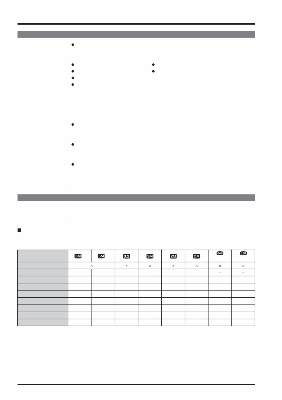
10 1. General FinePix Z1 Service Manual Power Supply and Others Optional accessories xD-Picture Card DPC-16 (16 MB)/DPC-32 (32 MB)/DPC-64 (64 MB)/DPC-128 (128 MB)/ DPC-256 (256 MB)/DPC-512 (512 MB)/DPC-M512 (512 MB)/DPC-M1GB (1 GB) Battery Charger BC-65 Rechargeable Battery NP-40 (750 mAh) AC Power Adapter AC-5VX AC Power Adapter AC-5VH/AC-5VHS Soft Case SC-FXZ1 Image Memory Card Reader DPC-R1 • Compatible with Windows 98/98 SE, Windows Me, Windows 2000 Professional, Windows XP or iMac, Mac OS 8.6 to 9.2.2, Mac OS X (10.1.2 to 10.2.2) and models that support USB as standard. • Compatible with xD-Picture Card of 16 MB to 512 MB, and SmartMedia of 3.3 V, 4 MB to 128 MB. PC Card Adapter DPC-AD • Compatible with xD-Picture Card of 16 MB to 512 MB, and SmartMedia of 3.3 V, 2 MB to 128 MB. CompactFlash Card Adapter DPC-CF • Windows 95/98/98 SE/Me/2000 Professional/XP • Mac OS 8.6 to 9.2/X (10.1.2 to 10.1.5) xD-Picture Card USB Drive DPC-UD1 • Compatible with xD-Picture Card of 16 MB to 512 MB • Windows 98/98 SE/Me/2000 Professional/XP • Mac OS 9.0 to 9.2.2/X (10.0.4 to 10.2.6) Cradle Cradle dimensions (W/H/D) 98.8 mm × 23.2 mm × 40.4 mm/3.9 in. × 0.9 in. × 1.6 in. Cradle mass (weight) Approx. 42 g/1.5 oz. Quality setting DPC-16 (16 MB) DPC-32 (32 MB) DPC-64 (64 MB) DPC-128 (128 MB) DPC-256 (256 MB) Image data size Number of recorded pixels F 2592 1944 2736 1824 2048 1536 1600 1200 640 480 640 480 320 240 N (30 fps) (30 fps) 6 12 25 51 102 2.5 MB DPC-512/M512 (512 MB) DPC-M1GB (1 GB) 205 412 12 25 50 102 204 1.3 MB 409 819 12 25 51 103 207 1.3 MB 414 830 19 40 81 162 325 780 KB 651 1305 25 50 101 204 409 630 KB 818 1639 122 247 497 997 1997 130 KB 3993 7995 13 sec. 27 sec. 55 sec. 111 sec. 223 sec. 7.4 min. 14.9 min. 26 sec. 54 sec. 109 sec. 219 sec. 7.3 min. 14.6 min. 29.3 min. Standard number of available frames/recording time per xD-Picture Card The number of available frames, recording time or file size varies slightly depending on the subjects photographed. Note also that the divergence between standard number of frames and the actual number of frames is greater for xD-Picture Cards with higher capacities.
Are you experiencing issues with your Fujifilm Finepix Z1 Camera? Why spend money on repairs when you can easily do it yourself with the help of this comprehensive service and repair manual? This manual is utilized by the Official Certified Fujifilm Technicians and will guide you through troubleshooting and repairing your camera.
With this manual, you will gain valuable insights into safety precautions, product specifications, troubleshooting, maintenance, disassembly and reassembly, adjustments, system diagrams, exploded views, and a replacement parts list. The manual is meticulously detailed with colored pictures and step-by-step instructions, ensuring the best possible repair and servicing of your device.
It's important to note that this is the official service and repair manual in PDF format, ensuring high resolution and excellent print quality. Upon payment, you will have instant access to the manual without any shipping fees or waiting for postal delivery, enabling you to commence your repairs promptly.
Specifications:
Language: English
Format: PDF
Pages: 90
Platform: Windows and MAC
If you are in search of a specific service manual, feel free to reach out to us with your request. With one of the largest service manual databases available, there's a good chance that we can assist you.
Recently Viewed
5,521,897Happy Clients
2,594,462eManuals
1,120,453Trusted Sellers
15Years in Business
Price:
Actual Price:
Fujifilm Fuji Finepix Z1 Service Manual & Repair Guide