Fujifilm Fuji Finepix S6000fd S6500fd Camera Service Repair Manual INSTANT
What's Included?
Lifetime Access
Fast Download Speeds
Online & Offline Access
Access PDF Contents & Bookmarks
Full Search Facility
Print one or all pages of your manual
THE COMPONENTS IDENTIFIED WITH THE MARK “ ” ON THE SCHEMATIC DIAGRAM AND IN THE PARTS LIST ARE CRITICAL FOR SAFETY. PLEASE REPLACE ONLY WITH THE COMPONENTS SPECIFIED ON THE SCHEMATIC DIAGRAM AND IN THE PARTS LIST. IF YOU USE PARTS NOT SPECIFIED, IT MAY RESULT IN A FIRE AND AN ELECTRICAL SHOCK. FUJI PHOTO FILM CO., LTD. Ref.No.:ZM00647-100 Printed in Japan 2006.09 DIGITAL CAMERA FinePix S6000fd/ S6500fd US/EU/EG/EE/AS/CH/JP-Model SERVICE MANUAL WARNING BECAUSE THIS PRODUCTIS RoHS LEAD-FREE COMPLIANT, USE THE DESIG- NATED AFTER-SELES PARTS AND THE DESIGNATED LEAD-FREE SOLDER WHEN PERFORMING REPAIRS. (Refer to page 3 to page 5) CAUTION
2 FinePix S6000fd/S6500fd Service Manual 7. CAUTION: FOR CONTINUED PROTECTION AGAINST FIRE HAZARD, REPLACE ONLY WITH SAME TYPE 2.5 AMPERES 125V FUSE. ATTENTION: AFIN D'ASSURER UNE PROTECTION PERMANENTE CONTRE LES RISQUES D'INCENDIE, REMPLACER UNIQUEMENT PAR UN FUSIBLE DE MEME, TYPE 2.5 AMPERES, 125 VOLTS. 8. WARNING: TO REDUCE THE ELECTRIC SHOCK, BE CAREFUL TO TOUCH THE PARTS. WARNING! HIGH VOLTAGE SAFETY CHECK-OUT After correcting the original problem, perform the following safety check before return the product to the customer. 1. Check the area of your repair for unsoldered or poorly soldered connections. Check the entire board surface for solder splasher and bridges. 2. Check the interboard wiring to ensure that no wires are “pinched” or contact high-wattage resistors. 3. Look for unauthorized replacement parts, particularly transistors, that were installed during a previous repair. Point them out to the customer and recommend their replacement. 4. Look for parts which, though functioning, show obvious signs of deterioration. Point them out to the customer and recommend their replacement. 5. Check the B + voltage to see it is at the values specified. 6. Make leakage - current measurements to determine that exposed parts are acceptably insulated from the supply circuit before returning the product to the customer. 2.5A 125V 2.5A 125V RISK OF FIRE- REPLACE FUSE AS MARKED
3 FinePix S6000fd/S6500fd Service Manual RoHS lead-free compliance Because this product is RoHS lead-free compliant, use the designated after-sales parts and the designated lead-free solder when performing repairs. <Background & Overview> With the exception of parts and materials expressly excluded from the RoHS directive (*1), all the internal connections and component parts and materials used in this product are lead-free compliant (*2) under the European RoHS directive. *1: Excluded items (list of the main lead-related items) • Lead included in glass used in fluorescent tubes, electronic components and cathode-ray tubes • Lead in high-melting-point solder (i.e. tin-lead solder alloys that contain 85% lead or more) • Lead in ceramic electronic parts (piezo-electronic devices) • Mercury contained in fluorescent tubes is also excluded. *2: Definition of lead-free A lead content ratio of 0.1 wt% or less in the applicable locations (solder, terminals, electronic components, etc.) <Reference> RoHS: The name of a directive issued by the European Parliament aimed at restricting the use of certain designated hazardous substances included in electrical and electronic equipment. Designated substances (6): Lead, mercury, cadmium, hexavalent chromium, polybrominated biphenyls (PBBs) and polybrominated diphenyl ether (PBDE) <Lead-free soldering> When carrying out repairs, use a designated lead-free solder, bearing in mind the differing work practices for conventional solder (eutectic) and lead-free solder. Differences in the soldering work for lead-free and eutectic solder When the soldering work practices for eutectic solder and lead-free solder are compared, the main differences are as shown below. In particular, when lead-free solder is used, the solder tends to be less workable than when eutectic solder is used. Accordingly, the soldering techniques used must take that into account. Difference The solder starts melting later. Poor wetting Solder feed rate is difficult to control. Wetting the insides of through holes is especially difficult. During repairs (or modifications) removing solder from inside through holes is difficult. There is serious carbonization of the soldering iron. The surface is not glossy. 1 2 3 4 5 6 7 Countermeasure The initial melting point of lead-free solder is high, so you have to get used to it. Move the tip of the soldering iron around to heat the entire connection to the melting temperature and assist wetting. Use the solder (wire) diameter and soldering iron that are best suited to connection being soldered. First apply solder to the area immediately around the through hold and then feed the solder into the hole. Use a suitable wicking wire (with a suitable method and heating) and a suction tool. Either put solder onto the soldering iron tip after completing the work, or turn the iron off frequently. Learn to recognize the appearance of the surface.
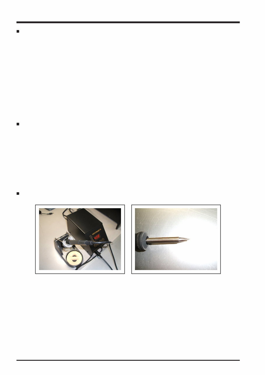
4 FinePix S6000fd/S6500fd Service Manual Setting temperature during lead-free soldering • Lead-free solder melting temperature The melting point of eutectic (Sn-Pb) solder is 183°C, while the melting point of lead-free solder (Sn-Ag-Cu) is 30°C higher at 220°C. • Soldering iron tip temperature The temperature setting for the soldering iron used should be such that the tip of the soldering iron is at the correct bonding temperature for the connection. This temperature is normally set at around 100°C higher than the melting point of the solder. However, the actual temperature should take into account the shape and size of the soldering iron tip, the heat tolerance of the connection and the workability of that temperature. • Correct bonding temperature The correct bonding temperature refers not to the temperature of the heat source, but to the bonding temperature that will give the best bond strength. Precautions when soldering with lead-free solder • Soldering iron maintenance Because of the high soldering iron temperature in lead-free soldering, there is rapid carbonization of the flux adhering to the tip of the soldering iron. (1) Always cover the tip of the soldering iron with solder when it is not being used. (2) If the tip is black from carbonization, wipe it gently with a paper towel soaked in alcohol until the solder will wet. • Uniform heating of the board and components To ensure that the lead-free solder wets the entire surface of the pattern and the lands despite its poor wetting characteristics, you must move the tip of the soldering iron over a wide area to raise the temperature of the entire connection. Soldering iron A soldering iron with a temperature control is best.
5 FinePix S6000fd/S6500fd Service Manual lead-free Wire diameter 0.8mm Solder type (Displayed symbol) SnAgCu Solder wire (thread) Use the lead-free solders specified below. Solder type: Sn96.5Ag3Cu0.5 (Displayed symbol: SnAgCu) Wire diameter: 0.6, 0.8 or 1.0 mm Sample: Flux Conventional flux can be used. Solder application wires (mesh, wicking wire, etc.) Conventional application wires can be used.
6 FinePix S6000fd/S6500fd Service Manual CONTENTS CONTENTS 1. General ........................................................ 1-1 1-1. Product specification .......................................... 1-1 1-2. Explanation of Terms .......................................... 1-4 1-3. Names of External Components ........................ 1-5 2. Disassembly ................................................ 2-1 2-1. Names of internal Components .......................... 2-1 2-2. Removing the REAR CONST ............................. 2-2 2-3. Disassembling the REAR CONST ..................... 2-4 2-4. Removing the MAIN PWB ASSY and FLASH PWB ASSY ............................................ 2-5 2-5. Removing the HOLDER BATTERY .................... 2-7 2-6. Removing the LENS ASSY ................................ 2-8 2-7. Removing the LENS HOLDER ........................... 2-9 2-8. Removing the FLASH CONST .......................... 2-11 2-9. Removing the FRONT CONST ......................... 2-11 2-10. Specifications for the sheet component attachment locations ........................................ 2-12 2-10-1. Affixing the REINFORCEMENT LCD ... 2-12 2-10-2. Affixing the MF SHEET ........................ 2-13 2-10-3. Affixing the FLASH PWB GASKET ...... 2-13 3. Schematics .................................................. 3-1 3-1. Cautions ............................................................. 3-1 3-2. Basic Block Names and Functions ..................... 3-1 3-3. Description of Main Block Functions .................. 3-2 3-3-1. Technical Overview ................................ 3-2 3-4. Block Diagram .................................................... 3-3 3-5. Overall connection Diagram ............................... 3-4 3-6. Circuit Diagrams ................................................. 3-5 3-6-1. AV BLOCK ............................................. 3-5 3-6-2. CAMERA BLOCK .................................. 3-6 3-6-3. DCDC BLOCK ....................................... 3-7 3-6-4. EVF BLOCK ........................................... 3-8 3-6-5. FDI BLOCK ............................................ 3-9 3-6-6. FLASH JACK BLOCK .......................... 3-10 3-6-7. KEY BLOCK .......................................... 3-11 3-6-8. KSW BLOCK ....................................... 3-12 3-6-9. LCD BLOCK ........................................ 3-13 3-6-10. MOTOR BLOCK .................................. 3-14 3-6-11. PMAN BLOCK ..................................... 3-15 3-6-12. PROCESS BLOCK (IO) ....................... 3-16 3-6-.13 PROCESS BLOCK (PW) ..................... 3-17 3-6-14. PROCESS BLOCK (SYS) ................... 3-18 3-6-15. AF LED BLOCK ................................... 3-19 3-6-16. CCD FPC BLOCK ................................ 3-19 3-6-17. CN BLOCK .......................................... 3-20 3-6-18. FSW BLOCK ........................................ 3-20 3-6-19. EMI BLOCK ......................................... 3-21 3-6-20. LCD DATA 7 BLOCK ............................ 3-22 3-6-21. MEDIA BLOCK .................................... 3-23 3-6-22. MSW BLOCK ....................................... 3-23 3-6-23. PLUNGER BLOCK .............................. 3-24 3-6-24. USB BLOCK ........................................ 3-24 3-6-25. RSW BLOCK ....................................... 3-25 3-6-26. XE BLOCK ........................................... 3-25 3-6-27. SSW BLOCK ....................................... 3-26 3-7. Mounted Parts Diagrams .................................. 3-27 3-7-1. FSW PWB ASSY ................................. 3-27 3-7-2. KSW PWB ASSY ................................ 3-28 3-7-3. MSW PWB ASSY ............................... 3-29 3-7-4. RSW PWB ASSY ................................ 3-30 3-7-5. SSW PWB ASSY ................................ 3-31 3-7-6. XE PWB ASSY ................................... 3-32 3-7-7. FLASH PWB ASSY .............................. 3-33 3-7-8. MAIN PWB ASSY ................................ 3-34
7 CONTENTS FinePix S6000fd/S6500fd Service Manual CONTENTS 4. Adjustments ................................................. 4-1 4-1. Important point before Adjustment ..................... 4-1 4-1-1. The handling of image files in internal memory .................................................. 4-1 4-1-2. Important point Adjustment when Replacing Major Parts ............................ 4-2 4-2. Measuring Instruments Used ............................. 4-2 4-3. Use Jig list .......................................................... 4-3 4-4. Calibration method of pattern box ...................... 4-3 4-5. Adjustment software installation ......................... 4-4 4-5-1. Various downloading software decompressions, preservation methods, and notes ............................................... 4-4 4-5-2. Installation of DSC jig driver ................... 4-5 4-5-3. Adjustment software initiation method ... 4-5 4-6. Initial Settings of the Adjustment Software ......... 4-6 4-7. Starting the Adjustment Software ....................... 4-9 4-8. [R] : Flash Memory Reset ................................. 4-12 4-9. [F4] : CCD Defect Correction / OFD Adjustment ............................................... 4-14 4-10. [F5] : Camera Adjustment ................................. 4-18 4-11. [ S ]: Shading compensation adjustment .......... 4-24 4-12. [F6] : AF Adjustment ......................................... 4-29 4-13. [F7] : Flash Adjustment ..................................... 4-32 4-14. [F1] : Battery Voltage Adjustment ..................... 4-34 4-15. [F2] : Mode Dial Adjustment ............................. 4-38 4-16. [F11] : Video Adjustment .................................. 4-40 4-17. [F3] : LCD Adjustment ...................................... 4-42 4-18. [F8] : Firmware Download ................................ 4-44 4-19. [F12] : End Setting ............................................ 4-46 5. Inspection .................................................... 5-1 5-1. Required Measuring Equipment ......................... 5-1 5-2. Connection of Measuring Equipment ................. 5-1 5-3. Inspection and Factory Settings ......................... 5-2 6. Parts List ...................................................... 6-1 6-1. Packing and Accessories ................................... 6-1 6-1-1. US-model ............................................... 6-1 6-1-2. JP-model ................................................ 6-2 6-1-3. EU-model ............................................... 6-3 6-1-4. EG-model ............................................... 6-4 6-1-5. EE-model ............................................... 6-5 6-1-6. EE-model (JP Production) ..................... 6-6 6-1-7. AS-model ............................................... 6-7 6-1-8. CH-model ............................................... 6-8 6-2. Cabi Front Block ................................................. 6-9 6-2-1. US/JP-model .......................................... 6-9 6-2-2. EU/EG/EE-model ..................................... 10 6-2-3. EE-model (JP Production) .................... 6-11 6-2-4. AS-model ............................................. 6-12 6-2-5. CH-model ............................................. 6-13 6-3. Cabi Rear Block ............................................... 6-14 6-3-1. US/EU/EG/EE/AS/CH-model ............... 6-14 6-3-2. JP-mode .............................................. 6-15 6-4. Electrical parts .................................................. 6-17 7. Appendix ...................................................... 7-1 7-1. List of Related Technical Updates Issued .......... 7-1
8 FinePix S6000fd/S6500fd Service Manual MEMO
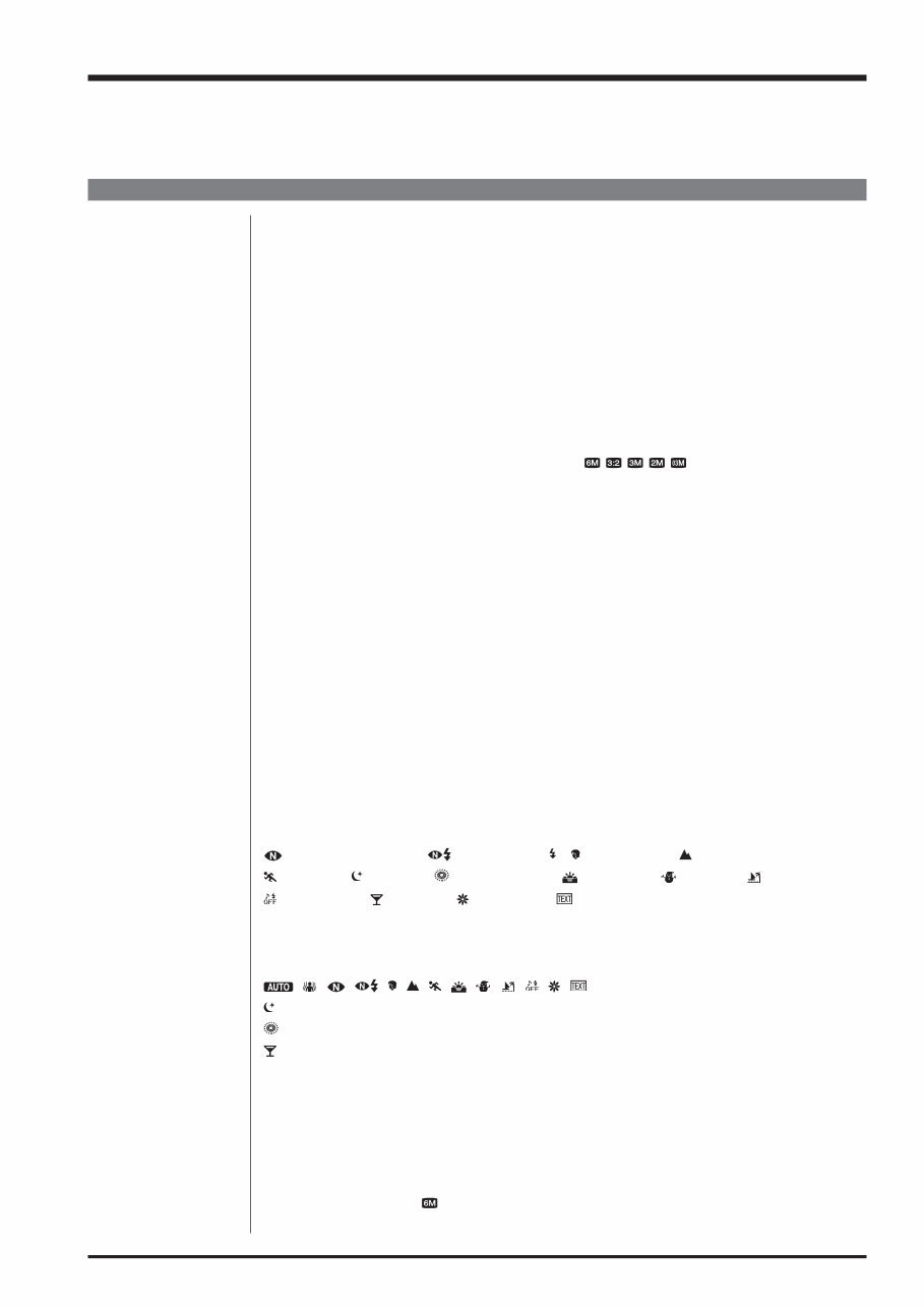
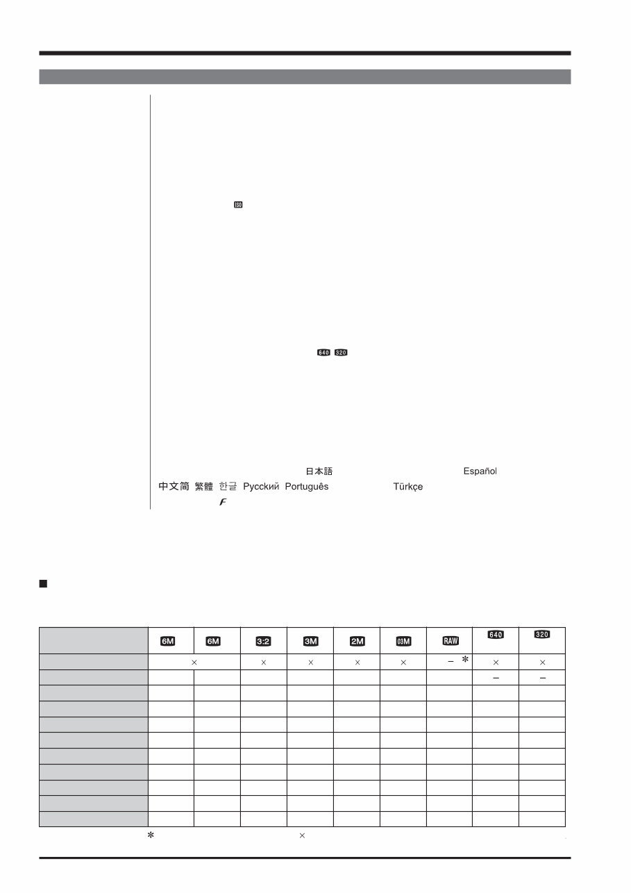
1-1 1. General FinePix S6000fd/S6500fd Service Manual 1. General 1-1. Product specification System Model Digital camera FinePix S6000fd / FinePix S6500fd Effective pixels 6.3 million pixels CCD 1/1.7-inch Super CCD HR Storage media Internal memory (approx. 10 MB)/xD-Picture Card (16/32/64/128/256/512 MB/1 GB/2 GB) File format Still image: DCF-compliant Compressed: Exif ver.2.2 JPEG, DPOF-compatible Uncompressed: CCD-RAW (RAF) *Design rule for Camera File System compliant DPOF compatible Movie: AVI format, Motion JPEG Audio: WAVE format, Monaural sound Number of recorded pixels Still image:2848 × 2136 pixels/3024 × 2016 pixels/2048 × 1536 pixels/ 1600 × 1200 pixels/640 × 480 pixels ( / / / / ) Lens Fujinon 10.7× optical zoom lens F2.8-F4.9 Focal length f=6.2 mm-66.7 mm (Equivalent to approx. 28 mm-300 mm on a 35 mm camera) Digital zoom Approx. 2.0× (10.7× optical zoom lens is used together: Max. zoom scale: approx. 21.4×) Aperture (Wide-angle) F2.8 to F11 Up to 13 steps in 1/3 EV increments Manual/Auto selectable Focal range Normal: Wide-angle: approx. 40 cm (1.3 ft.) to infinity (In High-speed shooting mode: approx. 2.0 m (6.6 ft.) to infinity) Telephoto: approx. 2.0 m (6.6 ft.) to infinity (In High-speed shooting mode: approx. 4.0 m (13.1 ft.) to infinity) Macro: Wide-angle: approx. 10 cm (3.9 in.) to 3.0 m (9.8 ft.) Telephoto: approx. 90 cm (3.0 ft.) to 3.0 m (9.8 ft.) Super macro: approx. 1 cm to 1.0 m (0.4 in. to 3.3 ft.) (Wide-angle only) Sensitivity AUTO/Equivalent to ISO 100/200/400/800/1600/3200 Photometry TTL 256-zones metering Multi, Spot, Average Exposure control Program AE (When using P mode : Program Shift is enabled)/Shutter priority AE/ Aperture priority AE/Manual exposure Scene position (NATURAL LIGHT), (NATURAL & ), (PORTRAIT), (LANDSCAPE), (SPORT), (NIGHT), (FIREWORKS), (SUNSET), (SNOW), (BEACH), (MUSEUM), (PARTY), (FLOWER), (TEXT) Picture Stabilization Available Intelligent Face Detection Available Exposure compensation -2 EV to +2 EV in 1/3 EV-step increments (P, S, A) Shutter speed , , , , , , , , , , , , : 1/4 sec. to 1/4000 sec*. : 4 sec. to 1/500 sec.* : 4 sec. to 1/2 sec.* : 1/45 sec. to 1/1000 sec.* (flash only). P, S, A: 4 sec. to 1/4000 sec.* M: 30 sec. to 1/4000 sec.* *depend on Exposure mode Continuous shooting Top-3: Number of recorded frames: up to 3 frames (Max. 2.2 frames/sec.) Final-3: Number of recorded frames: Last 3 frames before releasing the shutter button (Max. 2.2 frames/sec.) Long-period: Number of recorded frames: Depend on memory size. 1.5 sec. interval at N depending on quality level. (Max. 0.6 frames/sec.) Auto bracketing ± 1/3 EV, ± 2/3 EV, ± 1 EV
1-2 1. General FinePix S6000fd/S6500fd Service Manual System Focus Mode: Single-AF, Continuous AF, Manual focus/One-touch AF (when using Manual focus) AF system: TTL contrast-type, AF-assist illuminator AF frame selection: AF (CENTER), AF (MULTI), AF(AREA) White balance Automatic scene recognition/Preset (Fine, Shade, Fluorescent (Daylight), Fluorescent (Warm White), Fluorescent (Cool White), Incandescent) /Custom Self-timer Approx. 2 sec./10 sec. Flash type Popping the flash up automatically Effective range:( : AUTO): Wide-angle: approx. 60 cm-8.3 m (2.0 ft.-27.2 ft.) Telephoto: approx. 2.0 m-4.6 m (6.6 ft.-15.1 ft.) (Macro): Wide-angle: approx. 30 cm-2.0 m (1.0 ft.-6.6 ft.) Telephoto: approx. 90 cm-2.0 m (3.0 ft.-6.6 ft.) Flash mode Auto, Red-eye Reduction, Forced Flash, Suppressed Flash, Slow Synchro, Red-eye Reduction + Slow Synchro Viewfinder 0.33 inches, approx. 115,000 pixels low-temperature polysilicon TFT color LCD finder, Approx. 100% coverage LCD monitor 2.5 inches, Aspect ratio: 4:3; approx. 235,000 pixels Amorphous silicon TFT color LCD monitor, Approx. 100% coverage Movie 640 × 480 pixels/320 × 240 pixels ( / ) (30 frames per second with monaural sound) A series of continuous image can be recorded depending on the available space on an xD-Picture Card or internal memory. Photography functions Intelligent face detection, High-speed shooting, Best framing, Post shot assist window, Frame No. memory, Histograms Playback functions Intelligent face detection, Trimming, Automatic playback, Multi-frame playback, Sorting by date, Image rotate, Histograms (Highlight warning), Voice memo Other functions PictBridge, Exif print, Language ( , English, Francais, Deutsch, , Italiano, , , , , , Nederlands, ), Time difference, FinePix photo mode ( -mode), Discharging rechargeable batteries Standard number of available frames/recording time per xD-Picture Card and internal memory The number of available frames, recording time or file size varies slightly depending on the subjects photographed. Note also that the divergence between standard number of frames and the actual number of frames is greater for xD-Picture Cards with higher capacities. Quality setting 16 MB 32 MB 64 MB 128 MB 256 MB Image data size Number of recorded pixels F 2848 2136 3024 2016 2048 1536 1600 1200 640 480 640 480 320 240 N (30 fps) (30 fps) 5 10 21 42 85 3.0 MB 512 MB 170 10 6 20 42 84 169 1.5 MB 13.4 MB 339 10 20 42 84 169 1.5 MB 339 19 40 81 162 325 780 KB 651 25 50 101 204 409 630 KB 818 122 6 12 15 77 247 497 997 1997 130 KB 3993 13 sec. 27 sec. 55 sec. 111 sec. 223 sec. 7.4 min. 26 sec. 54 sec. 109 sec. 219 sec. 7.3 min. Internal memory (approx. 10 MB) 3 8 sec. 16 sec. 14.6 min. 1 GB 341 680 680 1305 1639 7995 14.9 min. 29.3 min. 2 GB 680 1360 1360 2558 3198 15992 29.8 min. 58.7 min. Number of recorded pixel is 4048 3036 when displaying images on PC by using FinePixViewer. 0 1 2 4 9 19 38 76 152
Get your hands on the professional technical service and repair manual for the Fujifilm Fuji Finepix S6000fd S6500fd Camera. This comprehensive manual is suitable for both DIY enthusiasts and experienced mechanics, providing easy-to-read text sections, high-quality diagrams, and step-by-step instructions for all repair areas.
The manual comes in PDF format, compatible with all Windows and Mac operating systems. It is designed in English and requires Adobe Reader and WinZip for access. Upon completing the payment, you will receive an instant download link, eliminating the need for shipping and allowing you to commence repairs immediately.
The manual covers general information, disassembly, schematics, adjustments, inspection, parts list, and appendix, ensuring you have all the necessary details at your fingertips. Save on postage and packaging while having the convenience of immediate access to this valuable resource.
Ensure your Fujifilm camera stays in optimal working condition with this cost-effective repair manual.
Thank you for visiting, and have a great day!
Recently Viewed
5,521,897Happy Clients
2,594,462eManuals
1,120,453Trusted Sellers
15Years in Business
Price:
Actual Price:
Fujifilm Fuji Finepix S6000fd S6500fd Camera Service Repair Manual INSTANT