Fujifilm Fuji FinePix M603 Camera Service Repair Manual INSTANT
What's Included?
Lifetime Access
Fast Download Speeds
Online & Offline Access
Access PDF Contents & Bookmarks
Full Search Facility
Print one or all pages of your manual
WARNING THE COMPORNENTS IDENTIFIED BY THE MARK “ ” ON THE SCHEMATHIC DIAGRAM AND IN THE PARTS LIST ARE CRITICAL FOR SAFETY. PLEASE REPLACE ONLY BY THE COMPONENTS SPECIFIED ON THE SCHEMATHIC DIAGRAM AND IN THE PARTS LIST. IF YOU USE WITH PART NUMBER UN-SPECIFIED, IT MAY RESULT IN A FIRE AND AN ELECTORICAL SHOCK. FUJI PHOTO FILM CO.,LTD. Ref.No.:ZM00466-103 Printed in Japan 2002.10(T.S.) U/E/EG-Model SERVICE MANUAL DIGITAL CAMERA FinePix M603
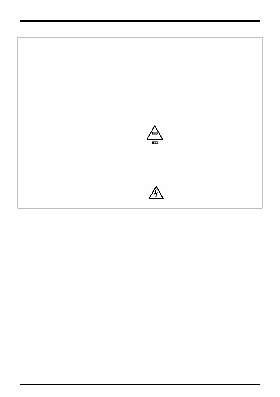
6. Make leakage - current measurements to determine that exposed parts are acceptably insulated from the supply circuit before returning the product to the customer. 7. CAUTION: FOR CONTINUED PROTECTION AGAINST FIRE HAZARD, REPLACE ONLY WITH SAME TYPE 2.5 AMPERES 125V FUSE. ATTENTION: AFIN D'ASSURER UNE PROTECTION PERMANENTE CONTRE LES RISQUES D'INCENDIE, REMPLACER UNIQUEMENT PAR UN FUSIBLE DE MEME, TYPE 2.5 AMPERES, 125 VOLTS. 8. WARNING: TO REDUCE THE ELECTRIC SHOCK, BE CAREFUL TO TOUCH THE PARTS. 2.5A125V 2.5A125V RISK OF FIRE- REPLACE FUSE AS MARKED WARNING! HIGH VOLTAGE SAFETY CHECK-OUT After correcting the original problem, perform the following safety check before return the product to the costomer. 1. Check the area of your repair for unsoldered or poorly sol dered connections. Check the entire board sur face for solder splasher and bridges. 2. Check the interboard wiring to ensure that no wires are pinched or contact high-wattage resistors. 3. Look for unauthorized replacement parts, particu larly tran sistors, that were installed during a previ ous repair. Point them out to the customer and rec ommend their replacement. 4. Look for parts which, though functioning, show obvi ous signs of deterioration. Point them out to the cus tomer and recommend their replacement. 5. Check the B + voltage to see it is at the values specified. FinePix M603 (U/E/EG) SERVICE MANUAL
3 FinePix M603 (U/E/EG) SERVICE MANUAL Table of Contents CONTENTS 1. General 1-1.Product specification ....................................................... 4 1-2.Explanation of Terms ....................................................... 6 1-3.Names of External Components .................................... 7 2. Disassembly 2-1.Names of internal Components ...................................... 8 2-2.Removing R CABI ASSY ................................................. 9 2-3.Removing LCD ASSY ...................................................... 10 2-4.Removing LCD FRAME ................................................... 11 2-5.Removing MAIN BLOCK ................................................. 11 2-6.Removing BOTTOM CABI ASSY ................................... 12 2-7.Removing MAIN PWB ASSY. ......................................... 12 2-8.Removing BATTERY TERMINAL UNIT ......................... 12 2-9.Removing CARD PWB ASSY ......................................... 13 2-10.Removing LENS ASSY .................................................. 13 2-11.Removing SIDE CABI ASSY ........................................ 14 2-12.Removing STROBE CONST ......................................... 14 2-13.Removing BARRIER MOTOR UNIT ............................ 15 2-14.Removing SW PWB ASSY ........................................... 15 3. Schematic 3-1.Cautions ............................................................................. 16 3-2.Basic block name and function explanation ................. 16 3-3.Primary Block Functions Description ............................ 17 3-3-1.Technical Outline .................................................. 17 3-3-2.Block Functions Descriptions .............................. 17 3-4.Block Diagram .................................................................. 18 3-5.Overall Connections ......................................................... 19 3-6.Board mounting diagram ................................................. 20 3-6-1.Printed wiring board of CARD PWB ASSY. ...... 21 3-6-2.Printed wiring board of MAIN PWB ASSY. ....... 21 3-6-3.Printed wiring board of SW PWB ASSY. ........... 22 3-6-4.Printed wiring board of STROBE CONST. ....... 22 4. Adjustment 4-1.Important point Adjustment when Replacing Major Parts .. 23 4-2.The order of adjustment when Major Parts are replaced ... 23 4-3.Measuring Instruments Used .......................................... 23 4-4.Use Jig list ......................................................................... 23 4-5.Calibration method of pattern box ................................. 24 4-6.Various downloading software decompressions, preservation methods, and notes ......................................... 24 4-7.Install the DSC jig driver and the PC adjustment software. 25 4-8.Setting up the Adjustment Software .............................. 26 4-9.Starting the Adjustment Software .................................. 28 4-10.[F4] CCD Defect Correction Adjustment ..................... 30 4-11.[F5] CAM Adjustment .................................................... 33 4-12.[F6] AF Adjustment ........................................................ 36 4-13.[F7] Flash Adjustment ................................................... 38 4-14.[F1] Battery Voltage Adjustment .................................. 40 4-15.[F12] End Setting ........................................................... 44 4-16.[F8] Firmware Download ............................................... 49 5. Inspection 5-1.Required Measuring Equipment ..................................... 51 5-2.Connection of Measuring Equipment ............................ 51 5-3.Inspection and Factory Settings .................................... 51 6. Parts List 6-1.Part list of U-Model .......................................................... 53 6-1-1.Packing and Accessories ..................................... 53 6-1-2.Cabinet F block ..................................................... 54 6-1-3.Internal block and Cabinet R block .................... 55 6-2.Part list of E-Model .......................................................... 56 6-2-1.Packing and Accessories ..................................... 56 6-2-2.Cabinet F block ..................................................... 57 6-2-3.Internal block and Cabinet R block .................... 58 6-3.Part list of EG-Model ....................................................... 59 6-3-1.Packing and Accessories ..................................... 59 6-3-2.Cabinet F block ..................................................... 60 6-3-3.Internal block and Cabinet R block .................... 61 6-4.Electrical Parts ................................................................. 62 6-4-1.Electrical Parts (U-Model) .................................... 62 6-4-2.Electrical Parts (E/EG-Model) ............................. 62 7. Appendix 7-1.List of Related Technical Updates Issued .................... 63
4 1.General FinePix M603 (U/E/EG) SERVICE MANUAL 1.General 1-1. Product specification System Model Digital camera FinePix M603 Number of effective pixels 3.1million pixels CCD sensor 1/1.7 inch Super CCD in an interwoven pattern Number of total pixels 3.3 million pixels Number of recorded pixels Still image: 2832 × 2128 pixels (6.03 million pixels)/2048 × 1536 pixels/1280 × 960 pixels/640 × 480 pixels Movie: 640 × 480 pixels (30 frames per second or 15 frames per second with monaural sound) 320 × 240 pixels (15 frames per second with monaural sound) Storage media xD-Picture Card (16MB to 128MB), Microdrive File format Still image: JPEG (Exif ver. 2.2) * Design rule for Camera File System compliant DPOF compatible Movie: AVI format, Motion JPEG Audio: WAV format Sensitivity Equivalent to ISO 160/200/400/800/1600 Lens Super EBC Fujinon 2× optical zoom lens Focus distance f = 8.7 mm-17.4 mm (Equivalent to 38 mm-76 mm on a 35 mm camera) Exposure control TTL 64-zones metering, Program AE, Exposure compensation available in Manual photography mode White balance Auto (In Manual modes, 7 positions can be selected.) Focal range Normal: Approx. 60 cm (2.0 ft.) to infinity Macro: Approx. 20 cm (7.9 in.) to 80 cm (2.6 ft.) Shutter Variable-speed, 1/4 sec. to 1/2000 sec. Aperture F3.2, F4, F5.2, F6.8, F8.8, F11 (automatically selected) Focus TTL contrast-type, Auto focus Self-Timer 10 sec. timer clock Erase modes ERASE FRAME, ERASE ALL FRAMES, FORMAT (initialize) LCD monitor 2.5 inches, low-temperature polysilicon TFT 118,000 pixels Flash Auto flash using flash control sensor Effective range: Wide-angle: Approx. 0.6 m-4.0 m (2.0 ft.-13.1 ft.) Telephoto-angle: Approx. 0.6 m-3.0 m (2.0 ft.-9.8 ft.) Flash modes: Auto, Red-Eye Reduction, Forced Flash, Suppressed Flash, Slow Synchro Video output NTSC (U.S.A./Canada model)/PAL (Europe model) Standard number of available shots/recording time per Media Image Data Size Microdrive 340MB Microdrive 1GB DPC-128 (128MB) DPC-64 (64MB) DPC-32 (32MB) DPC-16 (16MB) 147 443 53 26 13 6 311 938 113 56 28 13 589 1729 215 107 53 26 1119 3285 398 198 99 49 2729 8213 997 497 247 122 Approx. 10.0 min. Approx. 30.2 min. Approx. 220 sec. Approx. 109 sec. Approx. 54 sec. Approx. 26 sec. No. of recorded pixels Quality mode Approx. Approx. 1.2MB 2.4MB 2048 × 1536 Approx. 590KB 1280 × 960 Approx. 320KB Approx. 130KB 640 × 480 Approx. 5.1 min. Approx. 15.3 min. Approx. 111 sec. Approx. 55 sec. Approx. 27 sec. Approx. 13 sec. MOVIE Approx. 19.5 min. Approx. 58.7 min. Approx. 7.1 min. Approx. 213 sec. Approx. 106 sec. Approx. 52 sec. 6M F 6M N 0.3M (15 fps) (30 fps) (15 fps) 3M 1M 2832 × 2128
5 1.General FinePix M603 (U/E/EG) SERVICE MANUAL Input/Output Terminals DC Input To connect the AC power Adapter AC-5VS/AC-5VH/AC-5VHS (USB) socket For file transfer to a computer and connection to the optional cradle A/V Output Stereo mini-jack (1) Power Supply and Others Power supply Use one of the following Rechargeable Battery NP-60/NP-120 (sold separately) or AC Power Adapter AC-5VS/AC-5VHS Available shots/time using the battery (When fully charged) The number of shots shown here is an approximate guide to the number of con- secutive shots that can be taken based on 50% flash usage at normal tempera- tures. However, the actual number of available shots will vary depending on the ambient temperature when the camera is used and the amount of charge in the battery. The number of available shots will be lower in cold conditions. Conditions for use Temperature: 0 o C to +40 o C (+32 o F to +104 o F) 80% humidity or less (no condensation) Camera dimensions 64.5 mm × 93.3 mm × 31.6 mm/2.5 in. × 3.7 in. × 1.2 in. (W/H/D) (not including accessories and attachments) Camera mass (weight) 210 g/7.4 oz. (not including accessories, battery, xD-Picture Card or Microdrive) Weight for photography Approx. 240 g/8.5 oz. (including battery NP-60 and xD-Picture Card) Accessories l NP-60 Rechargeable Battery (1) Soft case included l 16 MB, xD-Picture Card (1) Supplied with: Anti-static case (1) l Strap (1) l LCD monitor hood (1) l Handgrip (1) l AC-5VS/AC-5VHS AC Power Adapter (1) Approx. 2 m (6.6 ft.) connection cord l A/V Cable (approx. 1.5 m (4.9 ft.), mini-plug (2.5 mm dia.) to pin-plug cable ×2) (1) l USB Interface Set (1) CD-ROM: Software for FinePix SX (1) FinePix M603 Special USB cable with Noise Suppression core (1) Software Quick Start Guide (1) l Owners Manual (1) Optional Accessories l xD-Picture Card DPC-16 (16MB)/DPC-32 (32MB)/DPC-64 (64MB)/DPC-128 (128MB) l BC-65 Battery Charger l NP-60/NP-120 Rechargeable Battery l AC-5VH/AC-5VHS AC Power Adapter l PictureCradle CP-FX 603 l SC-FX 603 l DPC-R1 Image Memory Card Reader Compatible with Windows 98/98 SE, Windows Me, Windows 2000 Profes- sional, Windows XP or iMac, Mac OS 8.6 to 9.2, Mac OS X (10.1.2 to 10.1.5) and models that support USB as standard. l DM-R1 Image Memory Card Reader Compatible with Windows 98 SE, Windows 2000 Professional (read-only), iMac DV and Power Macintosh PCs with FireWire as a standard feature. Mac OS 8.5.1 to 9.1. l DPC-AD PC Card Adapter Battery Type Media Type NP-60 xD-Picture Card Microdrive No. of still images Playback time No. of still images Movie shooting time Playback time 130 NP-120 230 120 min. 190 min. 120 220 50 min. 90 min. 70 min. 140 min.
6 1.General FinePix M603 (U/E/EG) SERVICE MANUAL 1-2.Explanation of Terms AF/AE Lock On the FinePix M603, pressing the shutter button down half way locks the focus and exposure settings (AF and AE lock). If you want to focus on a subject that is not centered in the frame or change the picture composition after the exposure is set, you can obtain good results by changing the composition after the AF and AE settings are locked. Auto Power Save Function If the camera is not used in any way for 30 seconds, this function switches fea- tures such as the LCD monitor off (Sleep mode) to prevent battery depletion and the waste of power when the AC power adapter is connected. If the camera is then left unused for a further period, the Auto Power Save function switches the camera off. This period can be set to 2 minutes or 5 minutes on this camera. l The Auto Power Off function does not operate in PC mode, during automatic playback, or if it is disabled during setup. DPOF Digital Print Order Format DPOF is a format used for recording information on a storage media (image memory card, etc.) that allows you to specify which of the frames shot using a digital camera are printed and how many prints are made of each image. EV A number that denotes Exposure Value. The EV is determined by the brightness of the subject and sensitivity (speed) of the film or CCD. The number is larger for bright subjects and smaller for dark subjects. As the brightness of the subject changes, a digital camera maintains the amount of light hitting the CCD at a con- stant level by adjusting the aperture and shutter speed. When the amount of light striking the CCD doubles, the EV increases by 1. Like- wise, when the light is halved, the EV decreases by 1. Frame rate (fps) The frame rate is a unit used to indicate the number of images (frames) played back per second. This camera shoots movie files at 10 consecutive frames per second, a rate that is expressed as 10 fps. By comparison, TV images are played at 30 fps. JPEG Joint Photographics Experts Group A file format used for compressing and saving color images. The compression ratio can be selected, but the higher the compression ratio, the poorer the quality of the expanded image. Motion JPEG A type of AVI (Audio Video Interleave) file format that handles images and sound as a single file. Images in the file are recorded in JPEG format. Motion JPEG can be played back by QuickTime 3.0 or later. PC Card A generic term for cards that meet the PC Card Standard. PC Card Standard A standard for PC cards determined by the PCMCIA. PCMCIA Personal Computer Memory Card International Association (US). Smear A phenomenon specific to CCDs whereby white streaks appear on the image when there is a very strong light source, such as the sun or reflected sunlight, in the photography screen. VGA/QVGA Graphics standards for PCs. Images are displayed at 640 × 480 and 320 × 240 pixels respectively. WAVE A standard format used on Windows systems for saving audio data. WAVE files have the .WAV file extension and the data can be saved in either compressed or uncompressed format. Uncompressed recording is used on this camera. WAVE files can be played back on a personal computer using the following software: Windows : MediaPlayer Macintosh: QuickTime Player * QuickTime 3.0 or later White Balance Whatever the kind of the light, the human eye adapts to it so that a white object still looks white. On the other hand, devices such as digital cameras see a white sub- ject as white by first adjusting the color balance to suit the color of the ambient light around the subject. This adjustment is called matching the white balance. A function that automatically matches the white balance is called an Automatic White Balance function. Exif Print Exif Print Format is a newly revised digital camera file format that contains a vari- ety of shooting information for optimal printing.
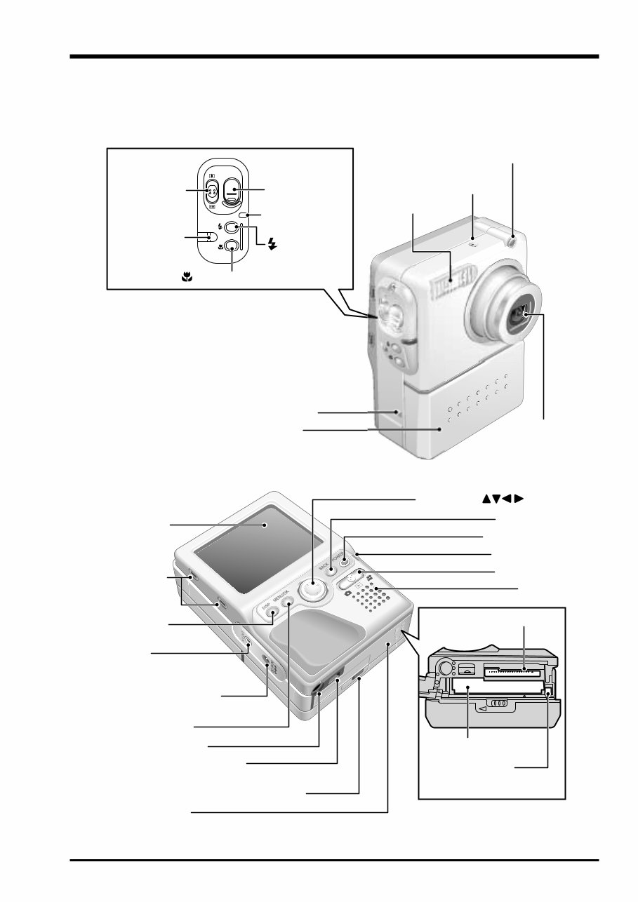
7 1.General FinePix M603 (U/E/EG) SERVICE MANUAL 1-3.Names of External Components LCD monitor Hood mount LCD monitor DISP button A/V OUT (Audio visual output)socket DC IN 5V(power input) socket MENU/OK button Slot cover Tripod mount Battery cover lock release catch Connection terminal/ Connection terminal cover 4-direction ( ) button BACK button Indicator lamp POWER button Speaker xD-Picture Card slot Microdrive slot Microdrive eject button Mode switch Microphone Flash Shutter button Flash button Macro button Strap mount Handgrip mount Battery cover Zoom switch Flash control sensor Self-timer lamp Lens
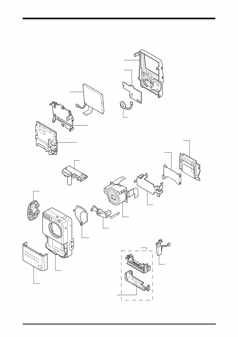
8 2. Disassembly FinePix M603 (U/E/EG) SERVICE MANUAL 2. Disassembly 2-1.Names of internal Components CARD COVER BATTERY PANEL ASSY STROBE CONST F CABI ASSY BARRIER ASSY BARRIER MOTOR UNIT SIDE CABI ASSY LENS ASSY MAIN FRAME CARD PWB ASSY EJECTOR MAIN PWB ASSY LCD ASSY LCD FRAME SPEAKER ASSY SW PWB ASSY R CABI ASSY BATTERY TERMINAL UNIT BOTTOM CABI ASSY
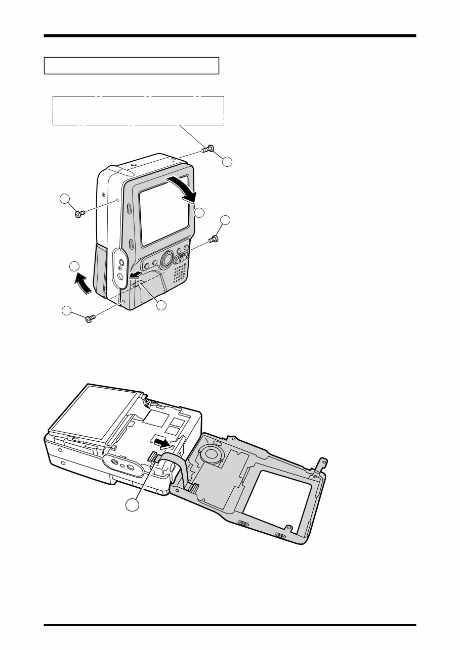
9 2. Disassembly FinePix M603 (U/E/EG) SERVICE MANUAL (1) Remove BATTERY PANEL ASSY in the direction of the arrow. (2) Remove five screws. (3) Remove R CABI ASSY in the direction of the arrow. [ Assembly ] Tighten the screw so as not to make the space in "R CABI ASSY" and "F CABI ASSY". 2-2.Removing R CABI ASSY Remove in the order indicated by circled numbers. <Step1> <Step2> (4) Remove connector (CN501). Screw of special shape. Use the driver of Jig number (ZJ00583-100). 2 2 1 1 2 2 3 4
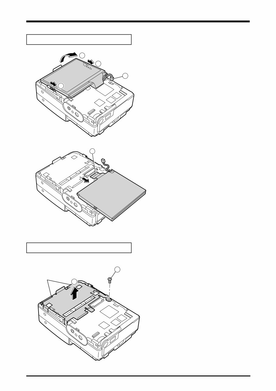
10 2. Disassembly FinePix M603 (U/E/EG) SERVICE MANUAL 2-3.Removing LCD ASSY (1) Remove CN700. (2) Move LCD ASSY in the direction of the arrow. (3) Raise LCD ASSY in the direction of the arrow. (4) Remove the lock of CN200, and remove LCD ASSY. <Step1> <Step2> Remove in the order indicated by circled numbers. (1) Remove one screw. (2) Remove LCD FRAME in the direction of the arrow. 2-4.Removing LCD FRAME <Step1> Remove in the order indicated by circled numbers. 1 2 2 3 4 hook 1 2 [ Assembly ] Assemble LCD ASSY in the reverse order of disassembling. [ Assembly ] Put the hole of LCD FLAME in two places in the hook of F CABI ASSY.
Get your hands on the complete professional technical service and repair manual for the Fujifilm Fuji FinePix M603 Camera. This manual is designed for both the do-it-yourselfer and the experienced mechanic, featuring easy-to-read text sections, top quality diagrams, and step-by-step instructions for all areas of repair. It is an inexpensive way to ensure your camera continues to work properly.
The manual comes in PDF format, compatible with all versions of Windows and Mac, and requires Adobe Reader and Win. Upon completing the payment, you will receive instant access to the manual without any shipping fees or waiting for postal delivery.
The manual covers general information, disassembly, schematics, adjustments, inspection, parts list, and appendix, providing you with immediate access to the information you need to start your repairs right away. Save money on postage and packaging and have the manual at your fingertips immediately.
Thanks for visiting, and have a nice day!
Recently Viewed
5,521,897Happy Clients
2,594,462eManuals
1,120,453Trusted Sellers
15Years in Business
Price:
Actual Price:
Fujifilm Fuji FinePix M603 Camera Service Repair Manual INSTANT