Fujifilm Fuji Finepix A340 Service Manual & Repair Guide
What's Included?
Lifetime Access
Fast Download Speeds
Online & Offline Access
Access PDF Contents & Bookmarks
Full Search Facility
Print one or all pages of your manual
WARNING THE COMPORNENTS IDENTIFIED BY THE MARK “ ” ON THE SCHEMATHIC DIAGRAM AND IN THE PARTS LIST ARE CRITICAL FOR SAFETY. PLEASE REPLACE ONLY BY THE COMPONENTS SPECIFIED ON THE SCHEMATHIC DIAGRAM AND IN THE PARTS LIST. IF YOU USE WITH PART NUMBER UN-SPECIFIED, IT MAY RESULT IN A FIRE AND AN ELECTORICAL SHOCK. FUJI PHOTO FILM CO.,LTD. Ref.No.:ZM00546-101 Printed in Japan 2004.04(T.S.) JP/US/EU/EG/GE/CA/AS-Model SERVICE MANUAL DIGITAL CAMERA A340
2 FinePix A340 SERVICE MANUAL 7. CAUTION: FOR CONTINUED PROTECTION AGAINST FIRE HAZARD, REPLACE ONLY WITH SAME TYPE 2.5 AMPERES 125V FUSE. ATTENTION: AFIN D'ASSURER UNE PROTECTION PERMANENTE CONTRE LES RISQUES D'INCENDIE, REMPLACER UNIQUEMENT PAR UN FUSIBLE DE MEME, TYPE 2.5 AMPERES, 125 VOLTS. 8. WARNING: TO REDUCE THE ELECTRIC SHOCK, BE CAREFUL TO TOUCH THE PARTS. 2.5A125V 2.5A125V RISK OF FIRE- REPLACE FUSE AS MARKED WARNING! HIGH VOLTAGE SAFETY CHECK-OUT After correcting the original problem, perform the following safety check before return the product to the customer. 1. Check the area of your repair for unsoldered or poorly soldered connections. Check the entire board surface for solder splasher and bridges. 2. Check the interboard wiring to ensure that no wires are “pinched” or contact high-wattage resistors. 3. Look for unauthorized replacement parts, particularly transistors, that were installed during a previous repair. Point them out to the customer and recommend their replacement. 4. Look for parts which, though functioning, show obvious signs of deterioration. Point them out to the customer and recommend their replacement. 5. Check the B + voltage to see it is at the values specified. 6. Make leakage - current measurements to determine that exposed parts are acceptably insulated from the supply circuit before returning the product to the customer.
3 Table of Contents FinePix A340 SERVICE MANUAL CONTENTS Page Page 1. General 1-1. Product specification .......................................................... 4 1-2. Explanation of Terms ......................................................... 6 1-3. Names of External Components ....................................... 7 2. Disassembly 2-1. Names of internal Components ........................................ 8 2-2. Removing CABI R ASSY ................................................... 9 2-3. Removing LCD CONST ..................................................... 9 2-5. Removing ST BLOCK ...................................................... 10 2-4. Removing DSC BLOCK ................................................... 10 2-6. Method of disassembling ST BLOCK ............................. 11 2-7. Removing LENS BLOCK ................................................. 11 2-8. Removing ENGINE PWB ASSY ...................................... 12 2-9. Removing BATTERY HOLDER ASSY ........................... 13 2-10. Removing LENS BARRIER ........................................... 13 3. Schematic 3-1. Cautions ............................................................................. 15 3-2. Basic block name and function explanation .................. 15 3-3.Functions of Primary Blocks ............................................. 16 3-3-1.Technical Outline .................................................... 16 3-3-2.MAIN Board Block Functions ................................ 16 3-3-3.ENGINE Board Block Functions ........................... 16 3-4. Block Diagram ................................................................... 17 3-5. Overall Connections ......................................................... 18 3-6. Board mounting diagram ................................................. 19 3-6-1. Printed wiring board of MAIN PWB ASSY ......... 19 3-6-2. Printed wiring board of ENGINE PWB ASSY .... 20 3-6-3. Printed wiring board of RSW PWB ASSY .......... 21 3-7.Circuit diagram .................................................................. 22 3-7-1. RSW BLOCK Circuit ............................................. 22 3-7-2. ENGINE BLOCK Circuit ........................................ 23 3-7-3. MAIN BLOCK Circuit ............................................. 24 4.Adjustment 4-1. Important point Adjustment when Replacing Major Parts .... 25 4-2. Measuring Instruments Used .......................................... 25 4-3. Use Jig list ......................................................................... 25 4-4. Method of remodeling Fx-A310Batt. jig ......................... 26 4-5. Calibration method of pattern box .................................. 27 4-6. Adjusting soft installation ................................................ 27 4-6-1. Various downloading software decompressions, preservation methods, and notes ................................... 27 4-6-2. Installation of DSC jig driver ................................ 28 4-6-3. Adjusting soft initiation method ........................... 28 4-7. Initial Settings of the Adjustment Software ................... 29 4-8. Starting the Adjustment Software ................................... 32 4-9. [R] : Flash Memory Reset ................................................ 35 4-10. [F5] : CAM Adjustment ................................................... 37 4-11. [F4] CCD Defect Correction Adjustment ..................... 40 4-12. [F6] : AF Adjustment ...................................................... 42 4-13. [F7] : Flash Adjustment ................................................. 44 4-14. [F1] : Battery Voltage Adjustment ................................ 46 4-15. [F3] : LCD Adjustment ................................................... 50 4-16. [F11] : Video Adjustment ............................................... 52 4-17. [F12] : End Setting ......................................................... 54 4-19. [F8] : Firmware Download ............................................. 58 5. Inspection 5-1. Required Measuring Equipment ..................................... 60 5-2. Connection of Measuring Equipment ............................. 60 5-3. Inspection and Factory Settings ..................................... 60 6. Parts List 6-1. Packing and Accessories ................................................ 62 6-1-1. US-MODEL ............................................................. 62 6-1-2. EU-MODEL ............................................................. 63 6-1-3. EG-MODEL ............................................................ 64 6-1-4. GE-MODEL ............................................................ 65 6-1-5. CA-MODEL ............................................................. 66 6-1-6. AS-MODEL ............................................................. 67 6-1-7. CH-MODEL ............................................................ 68 6-1-8. JP-MODEL ............................................................. 69 6-2. Mechanical parts (ALL-MODEL) ..................................... 70 6-3. Electronic parts ................................................................. 71 7.Appendix 7-1.Function of display for Firmware Version ...................... 72 7-2.List of Related Technical Updates Issued ...................... 73
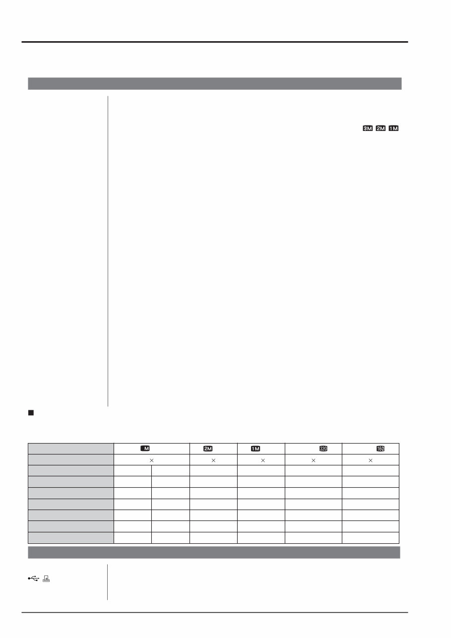
4 1.General FinePix A340 SERVICE MANUAL System Model Digital camera FinePix A340 Number of effective pixels 4.0 million pixels CCD sensor 1/2.7 inch square pixel CCD Number of total pixels 4.23 million pixels Number of recorded pixels Still image: 2272 × 1704 pixels/1600 × 1200 pixels/1280 × 960 pixels ( / / ) Movie: 320 × 240 pixels (10 frames per second without sound) 160 × 120 pixels (10 frames per second without sound) Storage media xD-Picture Card (16/32/64/128/256/512 MB) File format Still image: JPEG (Exif ver. 2.2) * Design rule for Camera File System compliant DPOF compatible Movie: AVI format, Motion JPEG Lens Fujinon 3× optical zoom lens, F2.8-F4.8 Aperture F2.8 to F4.8/F5.6 to F9.5 (automatically selected) Focal length f=5.7 mm to 17.1 mm (Equivalent to 38 mm to 114 mm on a 35 mm camera) Focal range Normal: Approx. 0.6 m (2.0 ft.) to infinity Macro: Approx. 0.1 m (3.9 in.) to 0.8 m (2.6 ft.) Shutter speed 2 sec. to 1/2000 sec. (combined with mechanical shutter) Focus TTL contrast-type, Auto focus Sensitivity Equivalent to ISO100 (at flash off) Photometry TTL 64-zones metering Exposure control Program AE Exposure compensation -2.1 EV to +1.5 EV in 0.3-step increments (in Manual mode) White balance Auto Manual modes, 7 positions can be selected Viewfinder Real image optical Approx. 80% coverage LCD monitor 1.5-inches, 60,000-pixel Amorphous silicon TFT, Approx. 90% coverage Flash Auto flash using flash control sensor Effective range: Wide-angle: Approx. 0.6 m to 3.5 m (2.0 ft. to 11.5 ft.) (Approx. 0.3 m to 0.8 m (1.0 ft. to 2.6 ft.): Macro) Telephoto: Approx. 0.6 m to 3.0 m (2.0 ft. to 9.8 ft.) Flash modes: Auto, Red-Eye Reduction, Forced Flash, Suppressed Flash, Slow Synchro*, Red-Eye Reduction + Slow Synchro* * In Manual mode Self-Timer 10 sec. Video output NTSC/PAL selectable Input/Output Terminals Video output socket 2.5 mm dia. jack (USB) socket For file transfer to a computer and connection to the optional cradle DC Input Socket for specified AC power adapter AC-3V (sold separately) Connection for the AC Power Adapter AC-3VW bundled with the cradle (sold separately) 1.General 1-1. Product specification Standard number of available frames/recording time per xD-Picture Card The number of available frames, recording time or file size varies slightly depending on the subjects photographed. Note also that the divergence between standard number of available frames and the actual number of available frames is greater for xD-Picture Cards with higher capacities. Quality Setting DPC-16 (16 MB) DPC-32 (32 MB) DPC-64 (64 MB) DPC-128 (128 MB) DPC-256 (256 MB) Image Data Size Number of recorded pixels 4M 8 16 33 66 134 FINE 1.5 MB NORMAL 760 KB 2272 1704 2M 25 50 101 204 409 620 KB 1600 1200 1M 33 68 137 275 550 460 KB 1280 960 Movie Approx. 98 sec. Approx. 199 sec. Approx. 6.6 min. Approx. 13.3 min. Approx. 26.7 min. – 320 240 Movie Approx. 5.6 min. Approx. 11.3 min. Approx. 22.7 min. Approx. 45.5 min. Approx. 91.2 min. DPC-512 (512 MB) 268 16 32 66 132 266 532 818 1101 Approx. 53.5 min. Approx. 182.5 min. – 160 120 4
5 1.General FinePix A340 SERVICE MANUAL Power Supply and Others Power supply Use one of the following: • 2×AA-size alkaline batteries • Rechargeable Battery NH-10 (sold separately) • 2×AA-size Ni-MH (Nickel-Metal Hydride) batteries (sold separately) • AC-3VW (PictureCradle CP-FXA10, sold separately) • AC Power Adapter AC-3V (sold separately) The number of available frames for battery operation given here is a guide to the number of consecutive shots that can be taken under FUJIFILM test conditions. • Batteries used: alkaline batteries bundled with the camera fully charged Ni-MH batteries or the NH-10 Rechargeable Battery • Shooting conditions: Measured at normal temperature with 50% flash use • Note: Because the number of available frames that can be taken varies depending on the capacities of alkaline batteries and the amount of charge in Ni-MH bat- teries or NH-10 Rechargeable Battery, the figures given here for the number of frames that can be taken using batteries are not guaranteed. At low tempera- tures, fewer pictures can be taken when the camera is running on batteries. Conditions for use Temperature: 0 o C to +40 o C (+32 o F to +104 o F); 80% humidity or less (no condensation) Camera dimensions 104.1 mm × 61.5 mm × 31.3 mm/4.1 in. × 2.4 in. × 1.2 in. (W/H/D) (not including accessories and attachments) Camera mass (weight) Approx. 145 g/5.1 oz. (not including accessories, batteries and xD-Picture Card) Weight for photography Approx. 193 g/6.8 oz. (including batteries and xD-Picture Card) Accessories 16 MB, xD-Picture Card (1) Included with: Anti-static case (1) LR6 AA-size alkaline Batteries (2) Strap (1) Video cable (1) 2.5 mm dia. plug-to-pin plug Approx. 1.5 m (4.9 ft.) USB cable with Noise Suppression core (1) Cradle adapter for FinePix A330 (1) CD-ROM: Software for FinePix AX (1) Owner’s Manual (1) Optional Accessories xD-Picture Card DPC-16 (16 MB)/DPC-32 (32 MB)/DPC-64 (64 MB)/DPC-128 (128 MB)/ DPC-256 (256 MB)/DPC-512 (512 MB) AC Power Adapter AC-3V Fujifilm Rechargeable Battery 2HR-3UF Fujifilm Battery Charger with Battery BK-NH/BK-NH2 (With Euro type or UK type plug) PictureCradle CP-FXA10 Rechargeable Battery NH-10 Carrying Case SC-FXA02 Image Memory Card Reader DPC-R1 • Compatible with Windows 98/98 SE, Windows Me, Windows 2000 Pro- fessional, Windows XP or iMac, Mac OS 8.6 to 9.2.2, Mac OS X (10.1.2 to 10.2.2) and models that support USB as standard. • Compatible with xD-Picture Card of 16 MB to 512 MB, and SmartMedia of 3.3V, 4 MB to 128 MB. PC Card Adapter DPC-AD • Compatible with xD-Picture Card of 16 MB to 512 MB, and SmartMedia of 3.3V, 2 MB to 128 MB. CompactFlash Card Adapter DPC-CF • Windows 95/98/98 SE/Me/2000 Professional/XP • Mac OS 8.6 to 9.2/X (10.1.2 to 10.1.5) xD-Picture Card USB Drive DPC-UD1 • Compatible with xD-Picture Card of 16 MB to 512 MB • Windows 98/98 SE/Me/2000 Professional/XP • Mac OS 9.0 to 9.2/X (10.0.4 to 10.2.6) Guide to the number of available frames for battery operation Alkaline batteries Approx. 140 frames Approx. 250 frames Rechargeable Battery NH-10 Approx. 220 frames Approx. 340 frames Ni-MH batteries 2300 mAh Approx. 290 frames Approx. 460 frames Battery Type With LCD monitor ON With LCD monitor OFF
6 1.General FinePix A340 SERVICE MANUAL 1-2. Explanation of Terms Deactivated batteries: Leaving an Ni-MH battery unused in storage for a long period may cause a rise in the level of substances that inhibit current flow inside the battery and result in a dormant battery. A battery in this state is referred to as deactivated. Because current flow is inhibited in a deactivated Ni-MH battery, the battery’s original level of performance cannot be achieved. DPOF: Digital Print Order Format DPOF is a format used for recording information on a storage media (image memory card, etc.) that allows you to specify which of the frames shot using a digital camera are to be printed and how many prints are made of each image. EV: A number that denotes Exposure Value. The EV is determined by the brightness of the subject and sensitivity (speed) of the film or CCD. The number is larger for bright subjects and smaller for dark subjects. As the brightness of the subject changes, a digital camera maintains the amount of light hitting the CCD at a con- stant level by adjusting the aperture and shutter speed. When the amount of light striking the CCD doubles, the EV increases by 1. Like- wise, when the light is halved, the EV decreases by 1. Frame rate (fps): The frame rate refers to the number of images (frames) that are photographed or played back per second. For example, when 10 frames are continuously photo- graphed in a 1-second interval, the frame rate is expressed as 10 fps. For reference, TV images are displayed at 30 fps. JPEG : Joint Photographics Experts Group A file format used for compressing and saving color images. The higher the com- pression rate, the greater the loss of quality in the decompressed (restored) im- age. Memory effect: If an Ni-MH battery is repeatedly charged without first being fully discharged, its performance may drop below its original level. This is referred to as the “memory effect”. Motion JPEG: A type of AVI (Audio Video Interleave) file format that handles images and sound as a single file. Images in the file are recorded in JPEG format. Motion JPEG can be played back by QuickTime 3.0 or later. PC Card: A generic term for cards that meet the PC Card Standard. PC Card Standard: A standard for PC cards determined by the PCMCIA. PCMCIA: Personal Computer Memory Card International Association (US). White Balance: Whatever the kind of the light, the human eye adapts to it so that a white object still looks white. On the other hand, devices such as digital cameras see a white subject as white by first adjusting the color balance to suit the color of the ambi- ent light around the subject. This adjustment is called matching the white bal- ance. Exif Print: Exif Print Format is a newly revised digital camera file format that contains a vari- ety of shooting information for optimal printing.
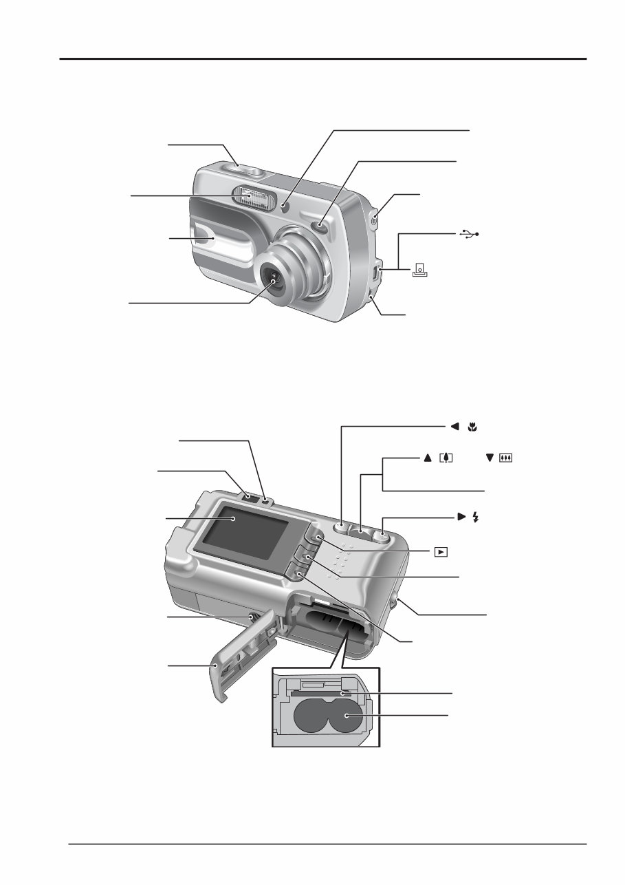
7 1.General FinePix A340 SERVICE MANUAL 1-3. Names of External Components VIDEO OUT (Video output) socket Self-timer lamp Shutter button DC IN 3V (Power input) socket Viewfinder window Power switch / lens cover Flash Cradle connection socket (USB)socket Lens xD-Picture Card slot Battery compartment Tripod mount Viewfinder Battery cover Viewfinder lamp LCD monitor DISP (Display) / BACK button Strap mount MENU / OK button / (Tele), / (Wide) / (Flash) button / (Macro) button Zoom switch ON (Playback) button
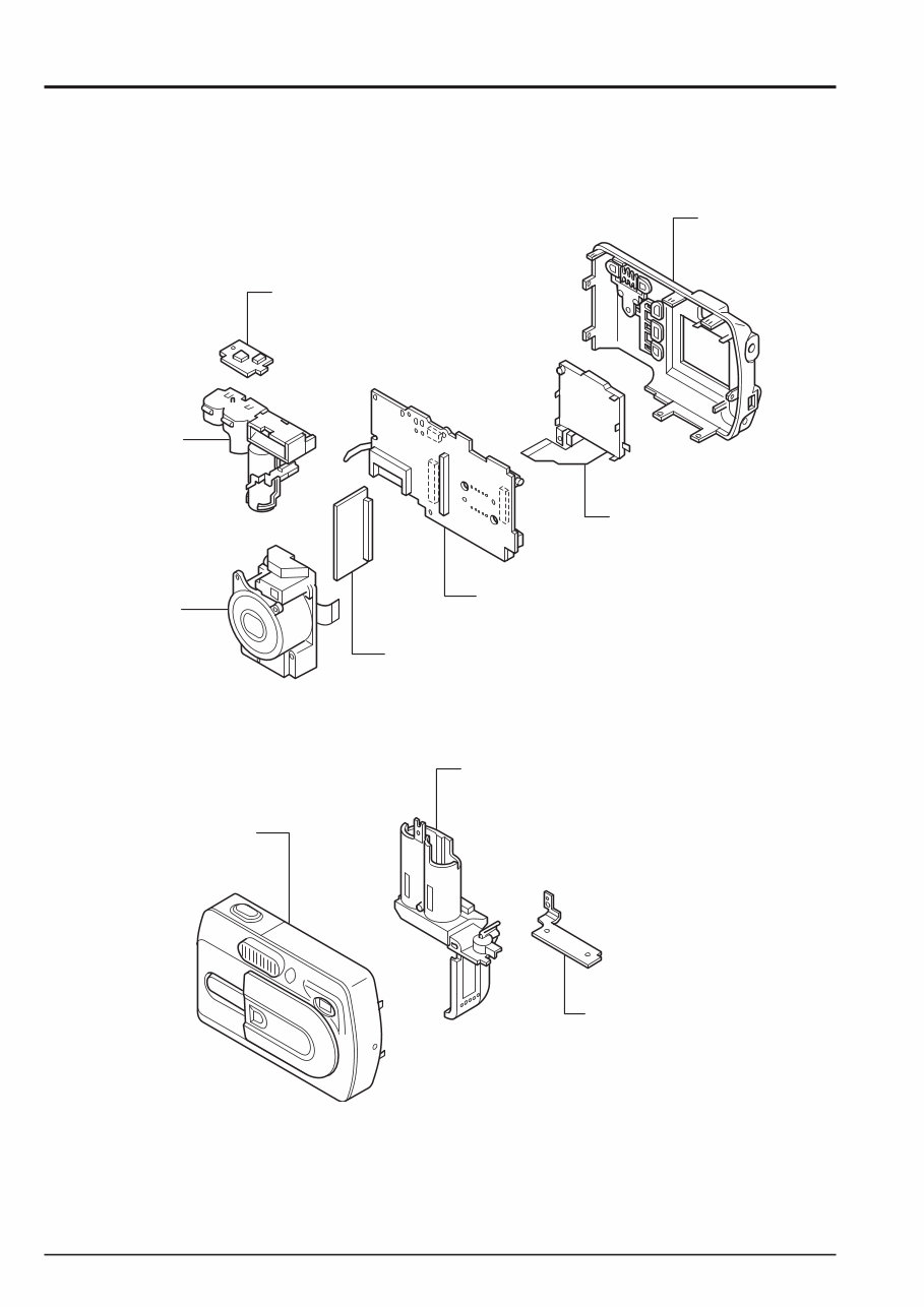
8 2. Disassembly FinePix A340 SERVICE MANUAL 2.Disassembly 2-1. Names of internal Components CABI R ASSY LCD CONST RSW PWB ASSY ENGINE PWB ASSY MAIN PWB ASSY ST BLOCK LENS BLOCK CABI F ASSY BATT ASSY BOTTOM PLATE
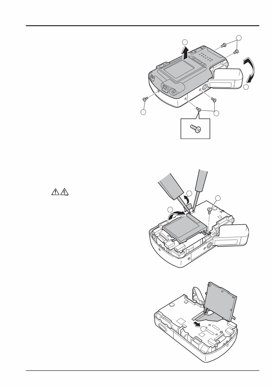
9 2. Disassembly FinePix A340 SERVICE MANUAL 2-2. Removing CABI R ASSY * Remove in the order indicated by circled numbers. < Step 1 > (1) Remove five screws. (** Remove it when there is a battery.) (2) Remove the battery cover. (3) Remove CABI R ASSY in the direction of the arrow. [ Assembly ] (1) Assemble it in the reverse order of disassembling. (2) Tighten the screw so as not to make the space in "CABI R ASSY" and "CABI F ASSY". Screw of special shape. Use the driver of Jig number (ZJ00583-100). 2-3. Removing LCD CONST * Remove in the order indicated by circled numbers. < Step 1 > (1) Peel off the UL tape, and discharge the flash. (2) Remove one screws. (3) Raise LCD CONST. < Step 2 > (4) Remove the lock of the connector, and remove LCD CONST. 1 1 1 2 3 1 2 3 4
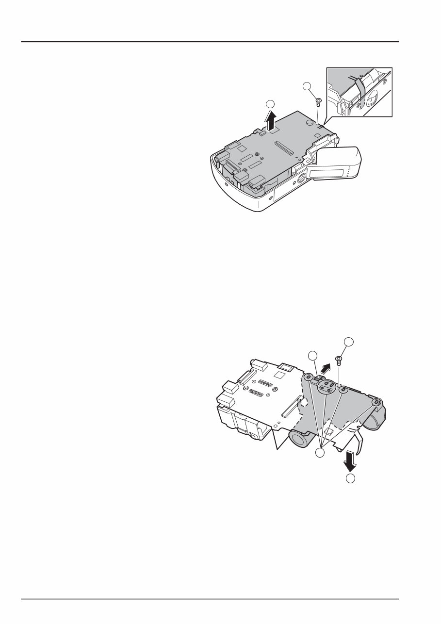
10 2. Disassembly FinePix A340 SERVICE MANUAL 2-4. Removing DSC BLOCK * Remove in the order indicated by circled numbers. < Step 1 > (1) Remove one screws. (2) Remove DSC BLOCK in the direction of the arrow. [ Assembly ] (1) Assemble it in the reverse order of disassembling. 2-5. Removing ST BLOCK * Remove in the order indicated by circled numbers. < Step 1 > (1) Pull out FFC from the connector. (2) Remove solder in seven places. (3) Remove one screws. (4) Remove ST BLOCK in the direction of the arrow. [ Assembly ] (1) Assemble it in the reverse order of disassembling. 1 2 2 4 3 1
Is your Fujifilm Finepix A340 Camera letting you down?
Why replace or spend lots of money on repairs while you can do it yourself? This service and repair manual is used by the Official Certified Fujifilm Technicians. It will help you to troubleshoot and repair your Camera!
Contents:
1 General
1-1 Product specification
1-2 Explanation of Terms
1-3 Names of External Components
2 Disassembly
2-1 Names of internal Components
2-2 Removing CABI R ASSY
2-3 Removing LCD CONST
2-5 Removing ST BLOCK
2-4 Removing DSC BLOCK
2-6 Method of disassembling ST BLOCK
2-7 Removing LENS BLOCK
2-8 Removing ENGINE PWB ASSY
2-9 Removing BATTERY HOLDER ASSY
2-10 Removing LENS BARRIER
3 Schematic
3-1 Cautions
3-2 Basic block name and function explanation
3-3 Functions of Primary Blocks
3-3-1 Technical Outline
3-3-2 MAIN Board Block Functions
3-3-3 ENGINE Board Block Functions
3-4 Block Diagram
3-5 Overall Connections
3-6 Board mounting diagram
3-6-1 Printed wiring board of MAIN PWB ASSY
3-6-2 Printed wiring board of ENGINE PWB ASSY
3-6-3 Printed wiring board of RSW PWB ASSY
3-7 Circuit diagram
3-7-1 RSW BLOCK Circuit
3-7-2 ENGINE BLOCK Circuit
3-7-3 MAIN BLOCK Circuit
4 Adjustment
4-1 Important point Adjustment when Replacing Major Parts
4-2 Measuring Instruments Used
4-3 Use Jig list
4-4 Method of remodeling Fx-A310Batt jig
4-5 Calibration method of pattern box
4-6 Adjusting soft installation
4-6-1 Various accessing software decompressions, preservation methods, and notes
4-6-2 Installation of DSC jig driver
4-6-3 Adjusting soft initiation method
4-7 Initial Settings of the Adjustment Software
4-8 Starting the Adjustment Software
4-9 [R] : Flash Memory Reset
4-10 [F5] : CAM Adjustment
4-11 [F4] CCD Defect Correction Adjustment
4-12 [F6] : AF Adjustment
4-13 [F7] : Flash Adjustment
4-14 [F1] : Battery Voltage Adjustment
4-15 [F3] : LCD Adjustment
4-16 [F11] : Video Adjustment
4-17 [F12] : End Setting
4-19 [F8] : Firmware
5 Inspection
5-1 Required Measuring Equipment
5-2 Connection of Measuring Equipment
5-3 Inspection and Factory Settings
6 Parts List
6-1 Packing and Accessories
6-1-1 US-MODEL
6-1-2 EU-MODEL
6-1-3 EG-MODEL
6-1-4 GE-MODEL
6-1-5 CA-MODEL
6-1-6 AS-MODEL
6-1-7 CH-MODEL
6-1-8 JP-MODEL
6-2 Mechanical parts (ALL-MODEL)
6-3 Electronic parts
7 Appendix
7-1 Function of display for Firmware Version
7-2 List of Related Technical Updates Issued
This service manual is very detailed with colored pictures and step-by-step instructions on how to repair/service this device the best way there is!
Please note: this is the OFFICIAL service and repair manual in .PDF format, no scanned-in or bootlegged copy. This manual is made in high resolution, so when you print the pages you need it is all in great quality!
***INSTANT access***
After your payment, you will have instant access to your manual! No shipping fee, no waiting on postal delivery, you can start doing your repairs right away!
Specifications
Language: English
Format: .PDF
Pages: 74
Platform: Windows and MAC
Looking for a service manual but can't find it anywhere? Please contact us with your request! As you can see we've got one of the largest service manual databases out there, so a good chance we can help you out!
Recently Viewed
5,521,897Happy Clients
2,594,462eManuals
1,120,453Trusted Sellers
15Years in Business
Price:
Actual Price:
Fujifilm Fuji Finepix A340 Service Manual & Repair Guide