FUJIFILM FINEPIX S5700 + 5700 Service & Repair Manual
What's Included?
Lifetime Access
Fast Download Speeds
Online & Offline Access
Access PDF Contents & Bookmarks
Full Search Facility
Print one or all pages of your manual
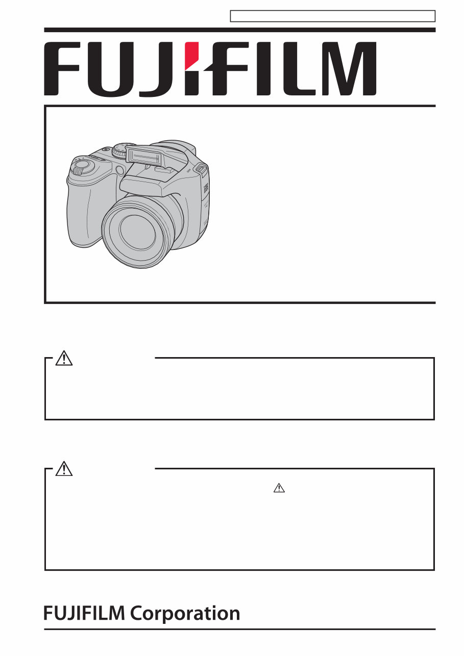
DIGITAL CAMERA FinePix S5700/ S700 SERVICE MANUAL US/EU/EG/EE/AS/CH/JP-model Ref.No.: ZM00676-101 Printed in Japan 2007.04 WARNING THE COMPONENTS IDENTIFIED WITH THE MARK " " ON THE SCHEMATIC DIAGRAM AND IN THE PARTS LIST ARE CRITICAL FOR SAFETY. PLEASE REPLACE ONLY WITH THE COMPONENTS SPECIFIED ON THE SCHEMATIC DIAGRAM AND IN THE PARTS LIST. IF YOU USE PARTS NOT SPECIFIED, IT MAY RESULT IN A FIRE AND AN ELECTRICAL SHOCK. CAUTION BECAUSE THIS PRODUCTIS RoHS LEAD-FREE COMPLIANT, USE THE DESIGNATED AFTER-SELES PARTS AND THE DESIGNATED LEAD-FREE SOLDER WHEN PERFORMING REPAIRS. (Refer to page 3 to page 5) Confidential: FUJIFILM Service Center Use Only
FinePix S5700/S700 Service Manual 2 Confidential: FUJIFILM Service Center Use Only 1. Check the area of your repair for unsoldered or poorly soldered connections. Check the entire board surface for solder splasher and bridges. 2. Check the interboard wiring to ensure that no wires are "pinched" or contact high-wattage resistors. 3. Look for unauthorized replacement parts, particularly transistors, that were installed during a previous repair. Point them out to the customer and recommend their replacement. 4. Look for parts which, though functioning, show obvious signs of deterioration. Point them out to the customer and recommend their replacement. 5. Check the B + voltage to see it is at the values specified. 6. Make leakage - current measurements to determine that exposed parts are acceptably insulated from the supply circuit before returning the product to the customer. 7. CAUTION: FOR CONTINUED PROTECTION AGAINST FIRE HAZARD, REPLACE ONLY WITH SAME TYPE 2.5 AMPERES 125V FUSE. ATTENTION: AFIN D'ASSURER UNE PROTECTION PERMANENTE CONTRE LES RISQUES D'INCENDIE, REMPLACER UNIQUEMENT PAR UN FUSIBLE DE MEME, TYPE 2.5 AMPERES, 125 VOLTS. 8. WARNING: TO REDUCE THE ELECTRIC SHOCK, BE CAREFUL TO TOUCH THE PARTS. SAFETY CHECK-OUT After correcting the original problem, perform the following safety check before return the product to the customer. WARNING! HIGH VOLTAGE 2.5A 125V 2.5A 125V RISK OF FIRE- REPLACE FUSE AS MARKED
FinePix S5700/S700 Service Manual 3 Confidential: FUJIFILM Service Center Use Only RoHS lead-free compliance Because this product is RoHS lead-free compliant, use the designated after-sales parts and the designated lead-free solder when performing repairs. <Background & Overview> With the exception of parts and materials expressly excluded from the RoHS directive (*1) , all the internal connections and component parts and materials used in this product are lead-free compliant (*2) under the European RoHS directive. *1:Excluded items (list of the main lead-related items) • Lead included in glass used in fluorescent tubes, electronic components and cathode-ray tubes • Lead in high-melting-point solder (i.e. tin-lead solder alloys that contain 85% lead or more) • Lead in ceramic electronic parts (piezo-electronic devices) • Mercury contained in fluorescent tubes is also excluded. *2: Definition of lead-free A lead content ratio of 0.1 wt% or less in the applicable locations (solder, terminals, electronic components, etc.) <Reference> RoHS: The name of a directive issued by the European Parliament aimed at restricting the use of certain designated hazardous substances included in electrical and electronic equipment. Designated substances (6): Lead, mercury, cadmium, hexavalent chromium, polybrominated biphenyls (PBBs) and polybrominated diphenyl ether (PBDE) <Lead-free soldering> When carrying out repairs, use a designated lead-free solder, bearing in mind the differing work practices for conventional solder (eutectic) and lead-free solder. Differences in the soldering work for lead-free and eutectic solder When the soldering work practices for eutectic solder and lead-free solder are compared, the main differences are as shown below. In particular, when lead-free solder is used, the solder tends to be less workable than when eutectic solder is used. Accordingly, the soldering techniques used must take that into account. Difference Countermeasure 1 The solder starts melting later. The initial melting point of lead-free solder is high, so you have to get used to it. 2 Poor wetting Move the tip of the soldering iron around to heat the entire connection to the melting temperature and assist wetting. 3 Solder feed rate is difficult to control. Use the solder (wire) diameter and soldering iron that are best suited to connection being soldered. 4 Wetting the insides of through holes is especially difficult. First apply solder to the area immediately around the through hold and then feed the solder into the hole. 5 During repairs (or modifications) removing solder from inside through holes is difficult. Use a suitable wicking wire (with a suitable method and heating) and a suction tool. 6 There is serious carbonization of the soldering iron. Either put solder onto the soldering iron tip after completing the work, or turn the iron off frequently. 7 The surface is not glossy. Learn to recognize the appearance of the surface.
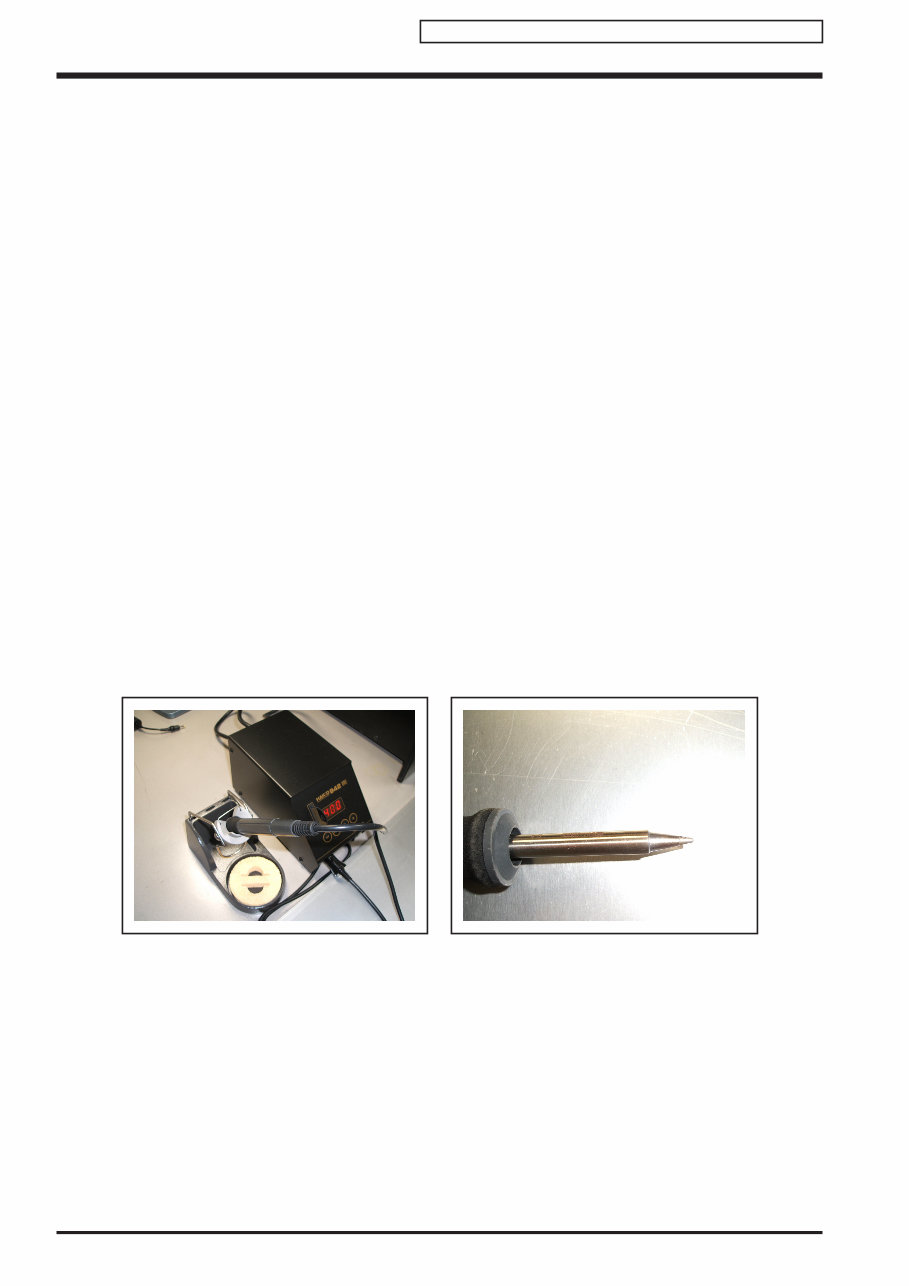
FinePix S5700/S700 Service Manual 4 Confidential: FUJIFILM Service Center Use Only Setting temperature during lead-free soldering • Lead-free solder melting temperature The melting point of eutectic (Sn-Pb) solder is 183°C, while the melting point of lead-free solder (Sn-Ag-Cu) is 30°C higher at 220°C. • Soldering iron tip temperature The temperature setting for the soldering iron used should be such that the tip of the soldering iron is at the correct bonding temperature for the connection. This temperature is normally set at around 100°C higher than the melting point of the solder. However, the actual temperature should take into account the shape and size of the soldering iron tip, the heat tolerance of the connection and the workability of that temperature. • Correct bonding temperature The correct bonding temperature refers not to the temperature of the heat source, but to the bonding temperature that will give the best bond strength. Precautions when soldering with lead-free solder • Soldering iron maintenance Because of the high soldering iron temperature in lead-free soldering, there is rapid carbonization of the flux adhering to the tip of the soldering iron. (1) Always cover the tip of the soldering iron with solder when it is not being used. (2) If the tip is black from carbonization, wipe it gently with a paper towel soaked in alcohol until the solder will wet. • Uniform heating of the board and components To ensure that the lead-free solder wets the entire surface of the pattern and the lands despite its poor wetting characteristics, you must move the tip of the soldering iron over a wide area to raise the temperature of the entire connection. Soldering iron A soldering iron with a temperature control is best.
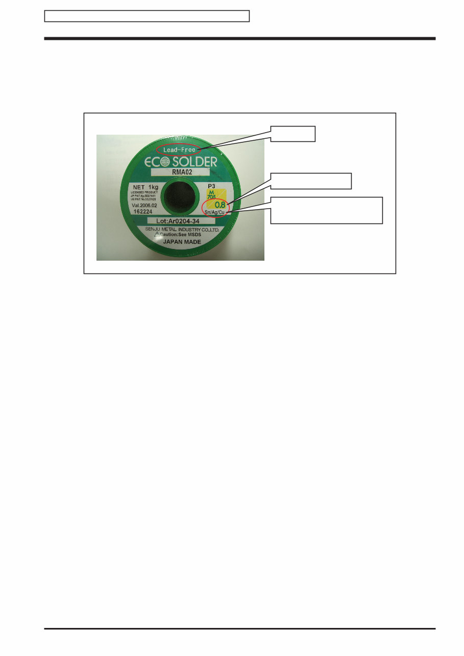
FinePix S5700/S700 Service Manual 5 Confidential: FUJIFILM Service Center Use Only Solder wire (thread) Use the lead-free solders specified below. Solder type: Sn96.5Ag3Cu0.5 (Displayed symbol: SnAgCu) Wire diameter: 0.6, 0.8 or 1.0 mm Sample: Flux Conventional flux can be used. Solder application wires (mesh, wicking wire, etc.) Conventional application wires can be used. lead-free Wire diameter 0.8mm Solder type (Displayed symbol) SnAgCu
FinePix S5700/S700 Service Manual 6 Confidential: FUJIFILM Service Center Use Only MEMO
FinePix S5700/S700 Service Manual 7 CONTENTS Confidential: FUJIFILM Service Center Use Only CONTENTS 1. General ....................................................... 1-1 1-1. Product specification............................................ 1-1 1-2. Explanation of Terms ........................................... 1-4 1-3. Names of External Components .......................... 1-5 2. Disassembly ............................................... 2-1 2-1. Names of internal Components ........................... 2-1 2-2. Removing the REAR CONST .............................. 2-2 2-3. Disassembling the REAR CONST ....................... 2-3 2-4. Removing the LCD .............................................. 2-4 2-5. Removing the COMPL PWB,CP-1 ...................... 2-5 2-6. Removing the SIDE CABI .................................... 2-7 2-7. Removing the LENS ............................................ 2-8 2-8. Removing the CCD PWB................................... 2-10 2-9. Removing the FLASH UNIT and EVF UNIT ...... 2-11 2-9-1. Disassembling the FLASH UNIT .......... 2-12 2-9-2. Disassembling the ST HOLDER .......... 2-14 2-10. Disassembling the LENS TOP HOLDER ........... 2-16 2-11. Disassembling the CABI FRONT....................... 2-18 2-12. Affixing locations for SPACERS and SHEETS ..2-19 2-12-1. Attaching the SPACER to the COMPL PWB,CP-1 .............................. 2-19 2-12-2. Attaching the CCD SPACER to the COMPL PWB,CA-1 .............................. 2-19 2-12-3. Attaching the SHEET and SPACER to the LCD HOLDER ............ 2-20 2-12-4. Attaching the MAIN/LCD SPACER and SHEET SHADE to the LCD.................. 2-20 2-12-5. Attaching the LCD SPACER A to the CABI BACK .......................................... 2-21 2-12-6. Attaching the LENS SPACER to the LENS HOLDER TOP............................ 2-21 3. Schematics ................................................. 3-1 3-1. Description of CCD circuit operation.................... 3-1 3-1-1. Overview ................................................ 3-1 3-1-2. IC931 (CCD imager) .............................. 3-1 3-1-3. IC901 (V driver) and IC905 (H driver) .... 3-1 3-1-4. IC905 (CDS, AGC and A/D converter) ... 3-1 3-2. Description of CP1 circuit operation .................... 3-2 3-2-1. Circuit Description .................................. 3-2 3-2-2. Outline of Operation ............................... 3-2 3-2-3. LCD Block .............................................. 3-2 3-2-4. EVF Block .............................................. 3-2 3-2-5. Lens Drive Block .................................... 3-3 3-3. Description of PWA Power Circuit Operation ....... 3-4 3-3-1. Overview ................................................ 3-4 3-4. Description of ST1 flash circuit operation ............ 3-5 3-4-1. Charging circuit ...................................... 3-5 3-4-2. Flash Circuit .......................................... 3-5 3-5. Description of SYA circuit operation..................... 3-6 3-5-1. Configuration and Functions .................. 3-6 3-5-2. Internal Communications Paths ............. 3-7 3-5-3. Key Operations ...................................... 3-7 3-5-4. Power Supply Control ............................ 3-8 3-6. Block Diagram ..................................................... 3-9 3-7. Overall connection Diagram .............................. 3-10 3-8. Circuit Diagrams ................................................ 3-11 3-8-1. CA1 BLOCK ......................................... 3-11 3-8-2. CCD BLOCK ........................................ 3-12 3-8-3. CP1 BLOCK (DMA).............................. 3-13 3-8-4. CP1 BLOCK (PWA) ............................. 3-14 3-8-5. CP1 BLOCK (STA) ............................... 3-15 3-8-6. CP1 BLOCK (SYA)............................... 3-16 3-8-7. CP1 BLOCK (TCA) .............................. 3-17 3-8-8. FLASH BLOCK .................................... 3-18 3-8-9. MAIN LCD DRIVER BLOCK ................ 3-19 3-8-10. POWER BLOCK .................................. 3-20 3-8-11. SYSTEM CONTROL BLOCK ............... 3-21 3-8-12. LENS BLOCK....................................... 3-23 3-8-13. PW1 BLOCK ........................................ 3-24 3-8-14. TB1 BLOCK ......................................... 3-25 3-8-15. TB1 BLOCK ......................................... 3-25 3-9. Mounted Parts Diagrams ................................... 3-26 3-9-1. CA1 PWB ASSY................................... 3-26 3-9-2. PW1 PWB ASSY .................................. 3-28 3-9-3. TB1 PWB ASSY ................................... 3-29 3-9-4. TB2 PWB ASSY ................................... 3-29 3-9-5. MAIN PWB ASSY................................. 3-31
FinePix S5700/S700 Service Manual 8 CONTENTS Confidential: FUJIFILM Service Center Use Only 4. Adjustments ............................................... 4-1 4-1. Important point before adjustment ....................... 4-1 4-1-1. The handling of image files in internal memory .................................................. 4-1 4-1-2. Adjustment when Replacing Major Parts ............................ 4-2 4-2. Measuring instruments used................................ 4-2 4-3. Use jig .................................................................. 4-2 4-4. Calibration method of pattern box........................ 4-3 4-5. Adjustment software installation .......................... 4-3 4-5-1. Various downloading software decompressions, preservation methods, and notes ............................................... 4-3 4-6. Connecting to the PC for Adjustment................... 4-4 4-7. Adjustment Software Description......................... 4-5 4-8. MAIN PWB ASSY initialization............................. 4-6 4-9. LENS Adjustment............................................... 4-10 4-10. AWB Adjustment ................................................ 4-13 4-11. CCD Defect Detection ....................................... 4-15 4-12. CCD Black Defect Detection.............................. 4-17 4-13. Updating the Firmware ...................................... 4-19 4-14. Completion Settings........................................... 4-22 5. Inspection ................................................... 5-1 5-1. Required Measuring Equipment .......................... 5-1 5-2. Connection of Measuring Equipment................... 5-1 5-3. Inspection and Factory Settings .......................... 5-2 CONTENTS 6. Parts List .................................................... 6-1 6-1. Silver model ......................................................... 6-1 6-1-1. Packing and Accessories ....................... 6-1 6-1-1-1. US-model (S700) ................... 6-1 6-1-1-2. EU-model (S5700) ................. 6-2 6-1-1-3. EG-model (S5700) ................. 6-3 6-1-1-4. EE-model (S5700) .................. 6-4 6-1-1-5. AS-model (S5700) .................. 6-5 6-1-1-6. CH-model (S5700) ................. 6-6 6-1-1-7. JP-model (S5700) .................. 6-7 6-1-2. Mechanical Block 1 ................................ 6-9 6-1-2-1. US/EU/EG/EE/AS/ CH-model (S5700/S700) ........ 6-9 6-1-2-2. JP-model (S5700) ................ 6-10 6-1-3. Mechanical Block 2 .............................. 6-11 6-1-3-1. US-model (S700) ................. 6-11 6-1-3-2. EU/EG/EE-model (S5700) ...6-12 6-1-3-3. CH-model (S5700) ............... 6-13 6-1-3-4. AS/JP-model (S5700) .......... 6-14 6-1-4. Flash Block........................................... 6-15 6-1-4-1. US-model (S700) ................. 6-15 6-1-4-2. EU/EG/EE/AS/CH/ JP-model (S5700) ................ 6-16 6-2. Black model ....................................................... 6-17 6-2-1. Packing and Accessories ..................... 6-17 6-2-1-1. US-model (S700) ................. 6-17 6-2-1-2. EU-model (S5700) ............... 6-18 6-2-1-3. EG-model (S5700) ............... 6-19 6-2-1-4. EE-model (S5700) ................ 6-20 6-2-1-5. AS-model (S5700) ................ 6-21 6-2-1-6. CH-model (S5700) ............... 6-22 6-2-1-7. JP-model (S5700) ................ 6-23 6-2-2. Mechanical Block 1 .............................. 6-25 6-2-2-1. US/EU/EG/EE/AS/ CH-model (S5700/S700) ...... 6-25 6-2-2-2. JP-model (S5700) ................ 6-26 6-2-3. Mechanical Block 2 .............................. 6-27 6-2-3-1. US-model (S700) ................. 6-27 6-2-3-2. EU/EG/EE-model (S5700) ...6-28 6-2-3-3. CH-model (S5700) ............... 6-29 6-2-3-4. AS/JP-model (S5700) .......... 6-30 6-2-4. Flash Block........................................... 6-31 6-2-4-1. US-model (S700) ................. 6-31 6-2-4-2. EU/EG/EE/AS/CH/ JP-model (S5700) ................ 6-32 6-3. Electrical parts ................................................... 6-33 7. Appendix .................................................... 7-1 7-1. List of Related Technical Updates Issued ............ 7-1
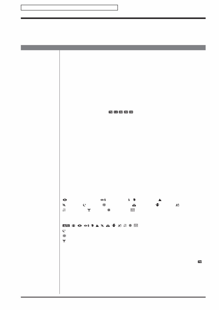
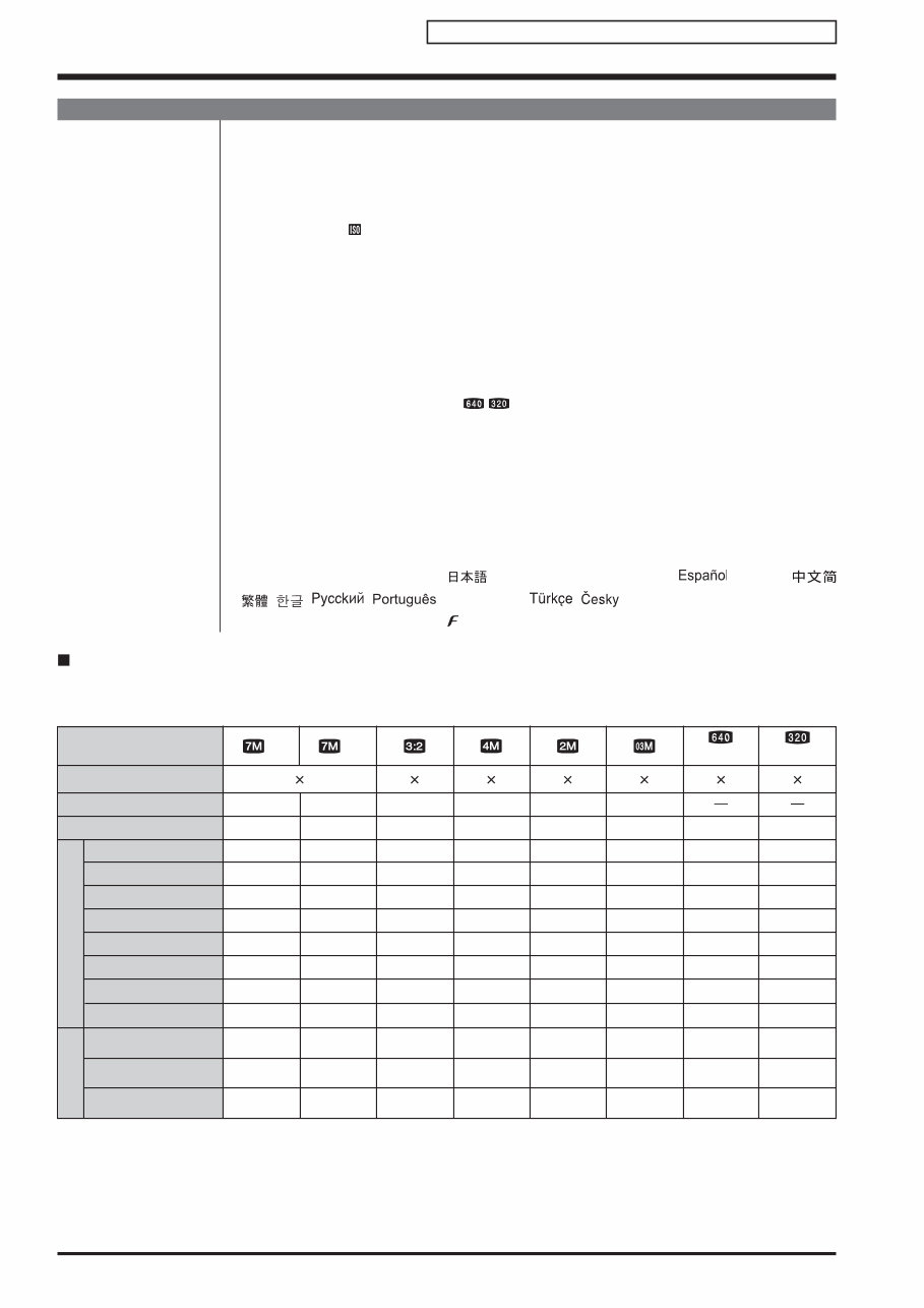
FinePix S5700/S700 Service Manual 1-1 1. General Confidential: FUJIFILM Service Center Use Only 1. General 1-1. Product specification System Model Digital camera FinePix S5700 / FinePix S700 Effective pixels 7.1 million pixels CCD 1/2.5-inch CCD Storage media Internal memory (approx. 27 MB)/xD-Picture Card (16/32/64/128/256/512 MB/1 GB/2 GB)/ SD Memory Card (FUJIFILM recommendation) File format Still image: DCF-compliant Compressed: Exif ver.2.2 JPEG, DPOF-compatible *Design rule for Camera File System compliant/DPOF compatible Movie: AVI format, Motion JPEG Audio: WAVE format, Monaural sound Number of recorded pixels Still image: 3072 × 2304 pixels/3072 × 2048 pixels/2304 × 1728 pixels/1600 × 1200 pixels/ 640 × 480 pixels ( / / / / ) Lens Fujinon 10× optical zoom lens F3.5 Focal length f=6.33 mm-63.3 mm (Equivalent to approx. 38 mm-380 mm on a 35 mm camera) Digital zoom Approx. 4.8× (10× optical zoom lens is used together: Max. zoom scale: approx. 48×) Aperture (Wide-angle) F3.5 to F13.6 in 1/3 EV increments Manual/Auto selectable Focal range Normal: Wide-angle: approx. 30 cm (1.0 ft.) to infinity (In High-speed shooting mode: approx. 1.0 m (3.3 ft.) to infinity) Telephoto: approx. 1.0 m (3.3 ft.) to infinity (In High-speed shooting mode: approx. 1.0 m (3.3 ft.) to infinity) Macro: Wide-angle: 4 cm to 3.0 m (1.6 in. to 9.8 ft.) Telephoto: 60 cm to 3.0 m (2.0 ft. to 9.8 ft.) Super macro: approx. 1 cm to 1.0 m (0.4 in. to 3.3 ft.) (Wide-angle only) Sensitivity AUTO/Equivalent to ISO 64/100/200/400/800/1600 (Standard output sensitivity) Photometry TTL 256-zones metering Multi, Spot, Average Exposure control Program AE (When using P mode : Program Shift is enabled)/Shutter priority AE/ Aperture priority AE/Manual exposure Scene position (NATURAL LIGHT), (NATURAL & ), (PORTRAIT), (LANDSCAPE), (SPORT), (NIGHT), (FIREWORKS), (SUNSET), (SNOW), (BEACH), (MUSEUM), (PARTY), (FLOWER), (TEXT) Picture Stabilization Available Exposure compensation -2 EV to +2 EV in 1/3 EV-step increments (P, A, S) Shutter speed , , , , , , , , , , , , : 1/4 sec. to 1/1000 sec*. : 3 sec. to 1/1000 sec.* : 4 sec. to 1/2 sec.* : 1/4 sec. to 1/1000 sec.* (flash only). P, A, S: 4 sec. to 1/1000 sec.* M: 4 sec. to 1/1000 sec.* *depend on Exposure mode Continuous shooting Top-3: Number of recorded frames: up to 3 frames (Max. 1.4 frames/sec.) Long-period: Number of recorded frames: Depend on memory size. 1.7 sec. interval at N depending on quality level. (Max. 0.6 frames/sec.) Auto bracketing ± 1/3 EV, ± 2/3 EV, ± 1 EV Focus Mode: Single AF, Continuous AF, Manual focus AF system: TTL contrast-type, AF-assist illuminator AF frame selection: AF (CENTER), AF (MULTI), AF(AREA)
FinePix S5700/S700 Service Manual 1-2 1. General Confidential: FUJIFILM Service Center Use Only System White balance Automatic scene recognition/Preset (Fine, Shade, Fluorescent (Daylight), Fluorescent (Warm White), Fluorescent (Cool White), Incandescent) /Custom Self-timer Approx. 2 sec./10 sec. Flash type Popping the flash up automatically Effective range: ( : 800): approx. 50 cm-6.2 m (1.6 ft.-20 ft.) (Macro): approx. 30 cm-3.0 m (1.0 ft.-9.8 ft.) Flash mode Auto, Red-eye Reduction, Forced Flash, Suppressed Flash, Slow Synchro, Red-eye Reduction + Slow Synchro Viewfinder 0.24 inches, approx. 230,000 pixels low-temperature polysilicon TFT color LCD finder, Approx. 97% coverage LCD monitor 2.5 inches, Aspect ratio: 4:3; approx. 230,000 pixels low-temperature polysilicon TFT color LCD monitor, Approx. 97% coverage Movie 640 × 480 pixels/320 × 240 pixels ( / ) (30 frames per second with monaural sound) A series of continuous image can be recorded depending on the available space on an Memory Card or internal memory. Photography functions High-speed shooting, Best framing, Post shot assist window, Frame No. memory, Histograms Playback functions Trimming, Slide Show, Multi-frame playback, Sorting by date, Image rotate, Histograms (Highlight warning), Voice memo Other functions PictBridge, Exif print, Language ( , English, Francais, Deutsch, , Italiano, , , , , , Nederlands, , , Magyar, Polski, Svenska), Time difference, FinePix photo mode ( -mode), Discharging rechargeable batteries Standard number of available frames/recording time per xD-Picture Card, SD Memory Card and internal memory The number of available frames, recording time or file size varies slightly depending on the subjects photographed. Note also that the divergence between standard number of frames and the actual number of frames is greater for Memory Card with higher capacities. (30 fps) 3072 2048 1600 1200 640 480 640 480 3.5MB 4 9 18 36 73 7 147 294 1.8MB 9 18 36 73 146 15 293 586 1.6MB 10 20 41 82 164 17 329 659 980KB 16 32 64 128 257 27 515 1031 630KB 25 51 102 204 410 44 819 1640 130KB 124 249 499 999 1999 215 3995 7996 17 sec. 34 sec. 70 sec. 2.3 min. 4.7 min. 9.3 min. 18.7 min. 30 sec. 3072 2304 2304 1728 586 1163 1305 2063 3199 15995 142 283 319 499 793 3868 285 568 638 999 1589 7746 568 1127 1265 2000 3100 15504 Quality setting 16 MB 32 MB 64 MB 128 MB 256 MB Image data size Number of recorded pixels xD-Picture Card SD Memory Card 512 MB Internal memory (approx. 27 MB) 1 GB 2 GB 512 MB 1 GB 2 GB 36.8 min. 9 min. 18.1 min. 35.6 min. (30 fps) 320 240 27 sec. 55 sec. 1.8 min. 3.7 min. 7.4 min. 14.8 min. 29.6 min. 47 sec. 59.2 min. 14.3 min. 28.7 min. 57.4 min. F N
Are you a Fujifilm camera owner in need of maintenance or repair? This official service repair manual is essential for saving time and money on upkeep. Whether you're a basic or advanced user, this manual provides invaluable assistance for addressing important camera issues.
This repair manual offers guidance on disassembly, repair, schematics, circuit diagrams, block diagrams, maintenance, adjustments, parts replacement, and more. Produced by the manufacturer, it provides accurate information, high-quality photos, and step-by-step instructions tailored to your specific camera model.
Manual Details:
Format: PDF
Pages: 134
Language: English
Compatible: Windows/Mac
Printable Pages: Yes
If you need Adobe Reader to open the file, you can download it for free from here.
Ensure a successful repair with this well-organized and comprehensive manual designed to meet your camera's specific needs. Purchase from us for guaranteed satisfaction. Feel free to contact us with any questions. Thank you.
Recently Viewed
5,521,897Happy Clients
2,594,462eManuals
1,120,453Trusted Sellers
15Years in Business
Price:
Actual Price:
FUJIFILM FINEPIX S5700 + 5700 Service & Repair Manual