— 2 — ENGLISH JAPANESE ENGLISH JAPANESE HVR-V1J/V1U/V1N/V1E/V1P/V1C SPECIFICATIONS These specifications are extracted from instruction manual of HVR-V1U/V1N. System Video recording system (HDV) 2 rotary heads, Helical scanning system Video recording system (DVCAM (DV)) 2 rotary heads, Helical scanning system Still image recording system Exif Ver. 2.2* 1 Audio recording system (HDV) Rotary heads, MPEG-1 Audio Layer-2, Quantization: 16 bits Fs48kHz (stereo) transfer rate: 384 kbps Audio recording system (DVCAM (DV)) Rotary heads, PCM system Quantization: 12 bits Fs32kHz (channel 1/2 stereo), Quantization: 16 bits Fs48kHz (channel 1/2 stereo) Video signal NTSC color, EIA standards 1080/60i specification Usable cassette Mini DV cassette with the mark printed or Mini DVCAM cassette with mark printed Tape speed (HDV) Approx. 18.812 mm/s Tape speed (DVCAM) Approx. 28.218 mm/s Tape speed (DV SP) Approx. 18.812 mm/s Recording/playback time (HDV) 63 min (using a PHDVM-63DM cassette) Recording/playback time (DVCAM) 41 min (using a PHDVM-63DM cassette) Recording/playback time (DV SP) 63 min (using a PHDVM-63DM cassette) Fast forward/rewind time Approx. 2 min 40 s (using a PHDVM- 63DM cassette and rechargeable battery pack) Approx. 1 min 45 s (using a PHDVM- 63DM cassette and AC Adaptor) Viewfinder Electric viewfinder (color, black and white) Image device 4.5 mm (1/4 type) 3CMOS sensor Recording Pixels (HDV/DV 16:9 still recording): Max. 1.20 Mega (1 440 × 810) pixels * 2 Gross: Approx. 1 120 000 pixels Effective (movie, 16:9): 1 037 000 pixels Effective (movie, 4:3): 778 000 pixels Effective (still, 16:9): 1 037 000 pixels Effective (still, 4:3): 778 000 pixels Lens Carl Zeiss Vario-Sonnar T 20 × (Optical), Approx. 30 × (Digital, when [D.EXTENDER] is set to [ON]) Focal length f=3.9 - 78 mm (5/32 ~ 3 1/8 in.) When converted to a 35 mm still camera * 3 37.4 - 748 m m (1 1/2 ~ 29 1/2 in.) (16:9), 45.7 - 914 m m (1 13/16 ~ 36 in.) (4:3) F1.6 - 2.8 Filter diameter: 62 mm (2 1/2 in.) Color temperature Indoor (3 200 K), Outdoor (5 800 K) Minimum illumination 4 lx (lux) (F 1.6) * 1 “Exif” is a file format for still images, established by the JEITA (Japan Electronics and Information Technology Industries Association). Files in this format can have additional information such as your camcorder’s setting information at the time of recording. * 2 Still image resolution is obtained by the unique pixel array of Sony’s ClearVid CMOS Sensor and image processing system (new Enhanced Imaging Processor). * 3 The focal length figures are actual figures resulting from wide angle pixel read out. Output connectors AUDIO/VIDEO output 10-pin connector Video signal: 1 Vp-p, 75Ω (ohms), unbalanced Luminance signal: 1 Vp-p, 75Ω (ohms), unbalanced Chrominance signal: 0.286 Vp-p (burst signal), 75Ω (ohms), unbalanced Audio signal: 461 mV (at load impedance 47 kΩ (kilohms)), Output impedance with less than 2.2 kΩ (kilohms) COMPONENT OUT jack Y: 1 Vp-p, 75Ω (ohms), unbalanced PB/ PR, CB/CR: +/- 350 mV, 75Ω (ohms), unbalanced HDMI OUT jack TypeA (19-pin) Input/Output connectors LANC jack Stereo mini-minijack (Ø 2.5 mm) INPUT1/INPUT2 jack XLR3-pin, female, -60 dBu: 3kΩ (kilohms) +4 dBu: 10kΩ (kilohms) (0 dBu=0.775 Vrms) USB jack mini-B HDV/DV jack i.LINK interface (IEEE 1394, 4-pin connector S100) LCD screen Picture 8.8 cm (3.5 type, aspect ratio 16:9) Total dot number 211 200 (960 × 220) General Power requirements DC 7.2 V (battery pack) DC 8.4 V (AC Adaptor) Average power consumption* During camera recording using the viewfinder with normal brightness: HDV recording 6.8 W DVCAM (DV) recording 6.6 W During camera recording using the LCD with normal brightness: HDV recording 6.8 W DVCAM (DV) recording 6.6 W Operating temperature 0 °C to + 40 °C (32 °F to 104 °F) Storage temperature -20 °C to + 60 °C (-4 °F to + 140 °F) Dimensions (approx.) 145 × 184 × 431 mm (5 3/4 × 7 1/4 × 17 in.) (w/h/d) including the projecting parts 145 × 184 × 431 mm (5 3/4 × 7 1/4 × 17 in.) (w/h/d) including the projecting parts with batterypack NP-F570 Mass (approx.) 1.5 kg (3 lb 6 oz) main unit only 1.9 kg (4 lb 2 oz) including the NP- F570 rechargeable battery pack, cassette (PHDVM-63DM), and lens hood with lens cover, microphone Supplied accessories AC Adaptor (1) Power cord (1) Wireless Remote Commander (1) A/V connecting cable (1) Component video cable (1) USB cable (1) Large eyecup (1) Rechargeable battery pack NP-F570 (1) Lens hood with lens cover (1) Wind Screen (1) Microphone (1) CD-ROM “Manuals for Digital HD Video Camera Recorder” (1) Operating Guide (1) See page 5-38. * When using the supplied microphone AC Adaptor AC-L15A Power requirements AC 100 - 240 V, 50/60 Hz Current consumption 0.35 - 0.18 A Power consumption 18 W Output voltage DC 8.4 V* Operating temperature 0 °C to 40 °C (32 °F to 104 °F) Storage temperature -20 °C to + 60 °C (-4 °F to + 140 °F) Dimensions (approx.) 56 × 31 × 100 mm (2 1/4 × 1 1/4 × 4 in.) (w/h/d) excluding the projecting parts Mass (approx.) 190 g (6.7 oz) excluding the power cord * See the label on the AC Adaptor for other specifications. Rechargeable batterypack NP-F570 Maximum output voltage DC 8.4 V Output voltage DC 7.2 V Capacity 15.8 Wh (2 200 mAh) Dimensions (approx.) 38.4 × 20.6 × 70.8 mm (1 9/16 × 13/16 × 2 7/8in.) (w/h/d) Mass (approx.) 100 g (3.5 oz) Operating temperature 0 °C to 40 °C (32 °F to 104 °F) Type Lithium ion Design and specifications are subject to change without notice.
— 4 — HVR-V1J/V1U/V1N/V1E/V1P/V1C • Abbreviation AR : Argentine model AUS : Australian model BR : Brazilian model CH : Chinese model CND : Canadian model EE : East European model HK : Hong Kong model J : Japanese model JE : Tourist model KR : Korea model NE : North European model Model information table Model HVR-V1J HVR-V1U HVR-V1N HVR-V1E HVR-V1P HVR-V1C Destination J US, CND E AEP E CH Color system NTSC NTSC NTSC PAL PAL PAL
— 5 — ENGLISH JAPANESE ENGLISH JAPANESE HVR-V1J/V1U/V1N/V1E/V1P/V1C SAFETY-RELATED COMPONENT WARNING!! COMPONENTS IDENTIFIED BY MARK 0 OR DOTTED LINE WITH MARK 0 ON THE SCHEMATIC DIAGRAMS AND IN THE PARTS LIST ARE CRITICAL TO SAFE OPERATION. REPLACE THESE COMPONENTS WITH SONY PARTS WHOSE PART NUMBERS APPEAR AS SHOWN IN THIS MANUAL OR IN SUPPLEMENTS PUBLISHED BY SONY. 1. Check the area of your repair for unsoldered or poorly-soldered connections. Check the entire board surface for solder splashes and bridges. 2. Check the interboard wiring to ensure that no wires are "pinched" or contact high-wattage resistors. 3. Look for unauthorized replacement parts, particularly transistors, that were installed during a previous repair. Point them out to the customer and recommend their replacement. 4. Look for parts which, through functioning, show obvious signs of deterioration. Point them out to the customer and recommend their replacement. 5. Check the B+ voltage to see it is at the values specified. 6. Flexible Circuit Board Repairing • Keep the temperature of the soldering iron around 270˚C during repairing. • Do not touch the soldering iron on the same conductor of the circuit board (within 3 times). • Be careful not to apply force on the conductor when soldering or unsoldering. Unleaded solder Boards requiring use of unleaded solder are printed with the lead- free mark (LF) indicating the solder contains no lead. (Caution: Some printed circuit boards may not come printed with the lead free mark due to their particular size.) : LEAD FREE MARK Unleaded solder has the following characteristics. • Unleaded solder melts at a temperature about 40°C higher than ordinary solder. Ordinary soldering irons can be used but the iron tip has to be applied to the solder joint for a slightly longer time. Soldering irons using a temperature regulator should be set to about 350°C. Caution: The printed pattern (copper foil) may peel away if the heated tip is applied for too long, so be careful! • Strong viscosity Unleaded solder is more viscous (sticky, less prone to flow) than ordinary solder so use caution not to let solder bridges occur such as on IC pins, etc. • Usable with ordinary solder It is best to use only unleaded solder but unleaded solder may also be added to ordinary solder. SAFETY CHECK-OUT After correcting the original service problem, perform the following safety checks before releasing the set to the customer. CAUTION Danger of explosion if battery is incorrectly replaced. Replace only with the same or equivalent type. ATTENTION AU COMPOSANT AYANT RAPPORT À LA SÉCURITÉ! LES COMPOSANTS IDENTIFÉS PAR UNE MARQUE 0 SUR LES DIAGRAMMES SCHÉMATIQUES ET LA LISTE DES PIÈCES SONT CRITIQUES POUR LA SÉCURITÉ DE FONCTIONNEMENT. NE REMPLACER CES COMPOSANTS QUE PAR DES PIÈSES SONY DONT LES NUMÉROS SONT DONNÉS DANS CE MANUEL OU DANS LES SUPPÉMENTS PUBLIÉS PAR SONY.
— 7 — HVR-V1J/V1U/V1N/V1E/V1P/V1C TABLE OF CONTENTS 1. SERVICE NOTE 1-1. Power Supply During Repairs ········································· 1-1 1-2. To Take Out a Cassette when not Eject (Force Eject) ·····1-1 1-3. Setting the “Forced Power On” Mode ····························· 1-1 1-4. Using Service Jig ····························································· 1-2 1-5. Self-diagnosis Function ··················································· 1-2 1-6. Method of Coping with Shift Lens Error ························ 1-4 2. DISASSEMBLY 2-1. Disassembly ····································································· 2-2 2-2. Method of Lens Unit Disassembly ·································· 2-9 3. BLOCK DIAGRAMS 3-1. Overall Block Diagram (1/8) ··········································· 3-1 3-2. Overall Block Diagram (2/8) ··········································· 3-2 3-3. Overall Block Diagram (3/8) ··········································· 3-3 3-4. Overall Block Diagram (4/8) ··········································· 3-4 3-5. Overall Block Diagram (5/8) ··········································· 3-5 3-6. Overall Block Diagram (6/8) ··········································· 3-6 3-7. Overall Block Diagram (7/8) ··········································· 3-7 3-8. Overall Block Diagram (8/8) ··········································· 3-8 3-9. Power Block Diagram (1/4) ············································· 3-9 3-10. Power Block Diagram (2/4) ··········································· 3-10 3-11. Power Block Diagram (3/4) ··········································· 3-11 3-12. Power Block Diagram (4/4) ··········································· 3-12 4. PRINTED WIRING BOARDS AND SCHEMATIC DIAGRAMS 4-1. Frame Schematic Diagrams ············································· 4-1 4-2. Schematic Diagrams ························································ 4-3 4-3. Printed Wiring Boards ··················································· 4-45 4-4. Mounted Parts Location ················································ 4-67 5. REPAIR PARTS LIST 5-1. Exploded Views ·······························································5-2 5-2. Electrical Parts List ······················································· 5-17 Section Title P age 6. ADJUSTMENTS Before Starting Adjustments ····················································· 6-1 1-1. Adjusting Items when Replacing Main Parts and Boards ·············································································· 6-2 1-2. List of Service Tools ························································6-4 6-1. Camera Section Adjustments ··········································· 6-6 1-1. Preparations before Adjustments (CAMERA Section) ··· 6-6 1-2. Initialization of EVR Data ··············································· 6-8 1-3. Camera System Adjustments ········································· 6-31 1-4. Electronic Viewfinder System Adjustments ·················· 6-74 1-5. LCD System Adjustments ············································· 6-79 6-2. Mechanism Section Adjustments ·································· 6-83 1. Preparations for Check, Adjustment and Replacement of Mechanism Block ································ 6-83 2. Periodic Inspection and Maintenance ···························· 6-83 3. Check, Adjustment and Replacement of Mechanical Parts ··························································· 6-89 4. Adjustment ·································································· 6-122 6-3. Video Section Adjustments ········································· 6-129 3-1. Preparations Before Adjustments ································ 6-129 3-2. System Control System Adjustments ·························· 6-131 3-3. Servo and RF System Adjustments ····························· 6-133 3-4. Video System Adjustments ··········································6-136 3-5. Audio System Adjustments ········································· 6-141 6-4. Service Mode ······························································· 6-146 4-1. Adjustment Remote Commander (RM-95) ················· 6-146 4-2. Adjustment Remote Commander (New Lanc Jig) ······ 6-147 4-3. Data Process ································································ 6-148 4-4. Service Mode ······························································· 6-149 Section Title P age * The camera color reproduction frame is shown on page 6-157 to 160.
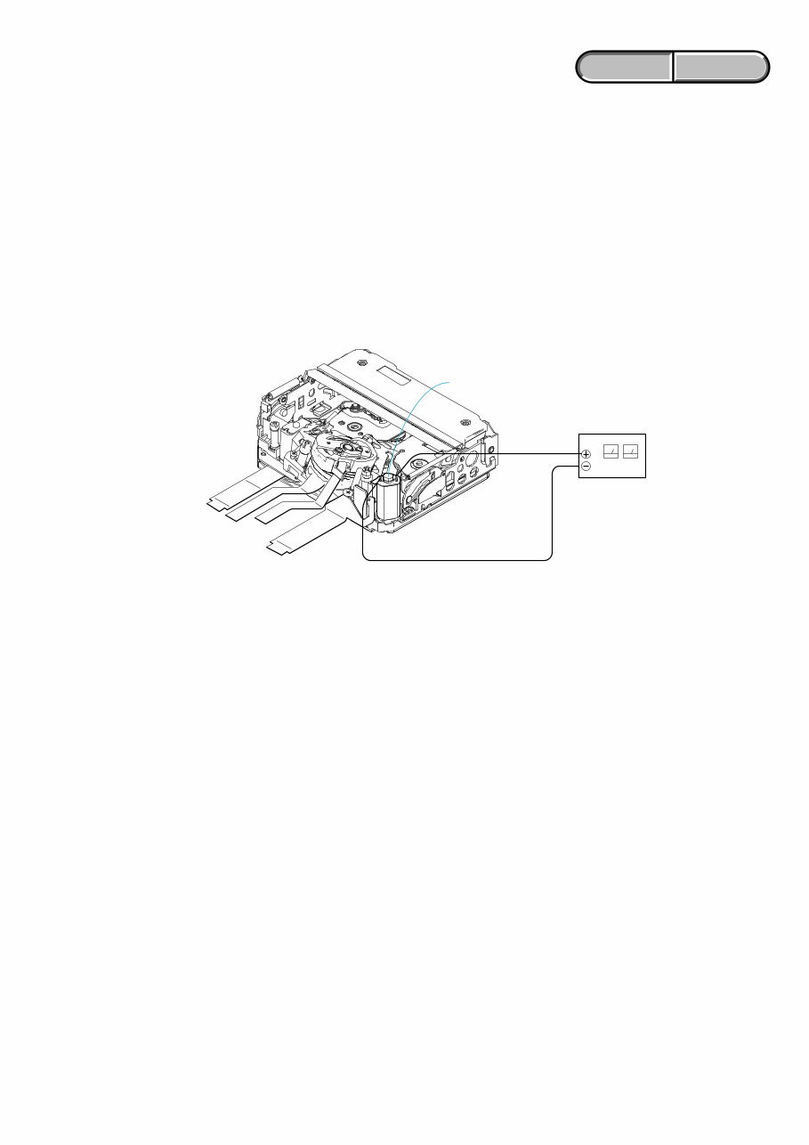
1-1 ENGLISH JAPANESE ENGLISH JAPANESE HVR-V1J/V1U/V1N/V1E/V1P/V1C 1. SERVICE NOTE 1-1. POWER SUPPLY DURING REPAIRS In this unit, about 10 seconds after power is supplied to the battery terminal using the regulated power supply (8.4V), the power is shut off so that the unit cannot operate. These following method is available to prevent this. Method: Use the AC power adaptor (AC-L15A). 1-2. TO TAKE OUT A CASSETTE WHEN NOT EJECT (FORCE EJECT) 1 Refer to “2. DISASSEMBLY” to remove the mechanism deck block. 2 Supply +4.5V from the DC power supply to the loading motor and unload with a pressing the cassette compartment. Loading motor DC power supply (+ 4.5Vdc) 1-3. SETTING THE “FORCED POWER ON” MODE It is possible to turn on power by adjustment remote commander (RM-95 or NEW LANC JIG). Operate the VTR function using the adjustment remote commander. 1-3-1. Setting the “Forced Camera Power ON” Mode 1) Select page: 0, address: 01, and set data:01. 2) Select page: A, address: 10, set data:01 and press the “PAUSE (Write) ” button of the adjustment remote commander. 1-3-2. Setting the “Forced VTR Power ON” Mode 1) Select page: 0, address: 01, and set data:01. 2) Select page: A, address: 10, set data:02 and press the “PAUSE (Write) ” button of the adjustment remote commander. 1-3-3. Exiting the “Forced Power ON” Mode 1) Select page: 0, address: 01, and set data:01. 2) Select page: A, address: 10, set data:00 and press the “PAUSE (Write) ” button of the adjustment remote commander. 3) Select page: 0, address: 01, and set data: 00.
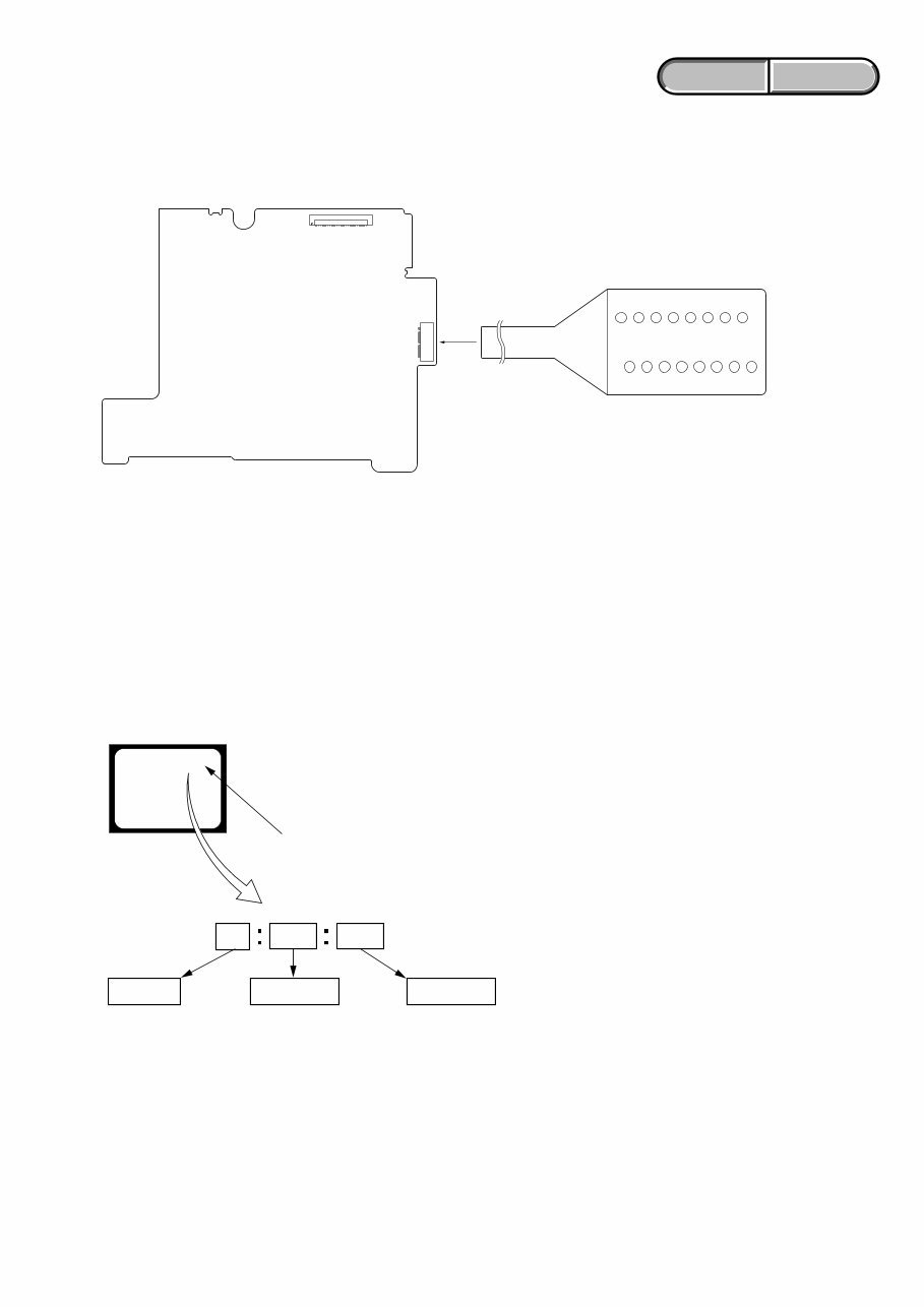
1-2 ENGLISH JAPANESE ENGLISH JAPANESE HVR-V1J/V1U/V1N/V1E/V1P/V1C 1-5. SELF-DIAGNOSIS FUNCTION 1-5-1. Self-diagnosis Function When problems occur while the unit is operating, the self-diagnosis function starts working, and displays on the viewfinder or LCD screen what to do. Details of the self-diagnosis functions are provided in the Instruction manual. 1-5-2. Self-diagnosis Display When problems occur while the unit is operating, the counter of the viewfinder or LCD screen shows a 4-digit display consisting of an alphabet and numbers, which blinks at 3.2 Hz. This 5-character display indicates the “repaired by:”, “block” in which the problem occurred, and “detailed code” of the problem. 1 1 3 1 C Repaired by: Refer to “1-5-3. Self-diagnosis Code Table”. Indicates the appropriate step to be taken. E.g. 31 ....Reload the tape. 32 ....Turn on power again. Block Detailed Code Blinks at 3.2Hz C : Corrected by customer H : Corrected by dealer E : Corrected by service engineer Viewfinder or LCD screen C : 3 1 : 1 1 1-4. USING SERVICE JIG Connect the CPC-7 jig connector (J-6082-382-A) to the CN1014 on the TT-003 board. TT-003 BOARD (SIDE B) CN1014 1 1 16 16 8 9 CPC-7 (J-6082-382-A)
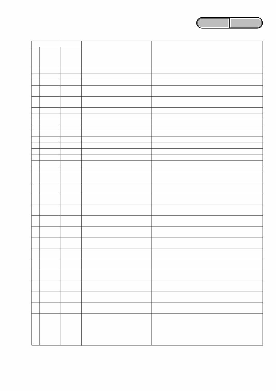
1-3 ENGLISH JAPANESE ENGLISH JAPANESE HVR-V1J/V1U/V1N/V1E/V1P/V1C 1-5-3. Self-diagnosis Code Table C C C C C C C C C C C C C C C C C C C C C C C C C C C C C C Block Function 0 4 2 1 2 2 3 1 3 1 3 1 3 1 3 1 3 1 3 1 3 1 3 1 3 1 3 1 3 1 3 1 3 2 3 2 3 2 3 2 3 2 3 2 3 2 3 2 3 2 3 2 3 2 3 2 3 2 3 2 Detailed Code 0 0 0 0 0 0 1 0 1 1 2 0 2 1 2 2 2 3 3 0 3 1 4 0 4 1 4 2 4 3 4 4 1 0 1 1 2 0 2 1 2 2 2 3 3 0 3 1 4 0 4 1 4 2 4 3 4 4 6 0 Symptom/State Non-standard battery is used. Condensation. Video head is dirty. LOAD direction. Loading does not complete within specified time UNLOAD direction. Loading does not complete within specified time T reel side tape slacking when unloading. S reel side tape slacking when unloading. T reel fault. S reel fault. FG fault when starting capstan. FG fault during normal capstan operations. FG fault when starting drum. PG fault when starting drum. FG fault during normal drum operations. PG fault during normal drum operations. Phase fault during normal drum operations. LOAD direction loading motor time- out. UNLOAD direction loading motor time-out. T reel side tape slacking when unloading. S reel side tape slacking when unloading. T reel fault. S reel fault. FG fault when starting capstan. FG fault during normal capstan operations. FG fault when starting drum. PG fault when starting drum. FG fault during normal drum operations. PG fault during normal drum operations. Phase fault during normal drum operations. Difficult to adjust focus (Cannot initialize focus.) Self-diagnosis Code Repaired by: Correction Use the InfoLITHIUM battery. Remove the cassette, and insert it again after one hour. Clean with the optional cleaning cassette. Load the tape again, and perform operations from the beginning. Load the tape again, and perform operations from the beginning. Load the tape again, and perform operations from the beginning. Load the tape again, and perform operations from the beginning. Load the tape again, and perform operations from the beginning. Load the tape again, and perform operations from the beginning. Load the tape again, and perform operations from the beginning. Load the tape again, and perform operations from the beginning. Load the tape again, and perform operations from the beginning. Load the tape again, and perform operations from the beginning. Load the tape again, and perform operations from the beginning. Load the tape again, and perform operations from the beginning. Load the tape again, and perform operations from the beginning. Remove the battery or power cable, connect, and perform operations from the beginning. Remove the battery or power cable, connect, and perform operations from the beginning. Remove the battery or power cable, connect, and perform operations from the beginning. Remove the battery or power cable, connect, and perform operations from the beginning. Remove the battery or power cable, connect, and perform operations from the beginning. Remove the battery or power cable, connect, and perform operations from the beginning. Remove the battery or power cable, connect, and perform operations from the beginning. Remove the battery or power cable, connect, and perform operations from the beginning. Remove the battery or power cable, connect, and perform operations from the beginning. Remove the battery or power cable, connect, and perform operations from the beginning. Remove the battery or power cable, connect, and perform operations from the beginning. Remove the battery or power cable, connect, and perform operations from the beginning. Remove the battery or power cable, connect, and perform operations from the beginning. Remove the battery or power cable, connect, and perform operations from the beginning. If it does not recover, inspect the focus MR sensor of lens block (Pin wl, ea of CN5802 on the YY-003 board). If not faulty, inspect the focus motor drive circuit (IC6004 on the YY-003 board).
Are you experiencing issues with your Sony HVR-V1 Professional Video Camera? Instead of replacing it, consider upgrading or repairing it yourself with the help of this comprehensive service and repair manual. This manual is utilized by Official Certified Sony Technicians and provides invaluable assistance in troubleshooting and repairing your Video Camera.
Key features of this manual include:
Safety & Precautions
Product Specifications
Disassembly & Reassembly
Troubleshooting
Adjustments
Block Diagrams
Schematic Diagrams
Printed Wiring Boards
Exploded Views
Replacement parts list
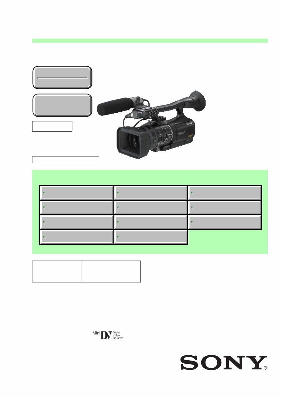
This service manual covers ALL HVR-V1 models, including Sony HVR-V1J, Sony HVR-V1U, Sony HVR-V1N, Sony HVR-V1E, Sony HVR-V1P, and Sony HVR-V1C. It is highly detailed and includes illustrated pictures and step-by-step instructions for optimal device repair and servicing.
Notably, this is the OFFICIAL service and repair manual in PDF format, ensuring the highest resolution for quality printing. You can conveniently print this manual from any printer and computer, with no shipping fees or waiting for postal delivery, providing instant access after payment.
Specifications:
Language: English
Format: PDF
Pages: 504
Platform: Windows and MAC
If you are unable to find a specific service manual, feel free to reach out to us with your request. With the most comprehensive service manual database available, there's a good chance we can assist you!






 Lifetime Access




