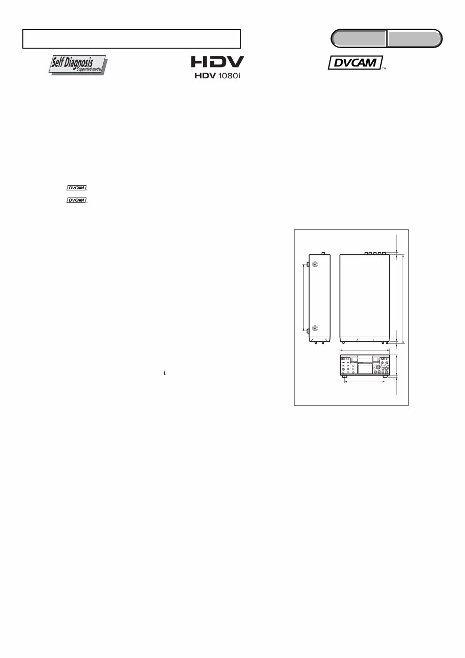
— 4 — HVR-M25J/M25U/M25N/M25E/M25P/M25C Model information table • Abbreviation AR : Argentine model AUS : Australian model BR : Brazilian model CH : Chinese model CND : Canadian model EE : East European model HK : Hong Kong model J : Japanese model JE : Tourist model KR : Korea model NE : North European model Model HVR-M25J HVR-M25U HVR-M25N HVR-M25E HVR-M25P HVR-M25C Destination J US, CND E AEP E CH
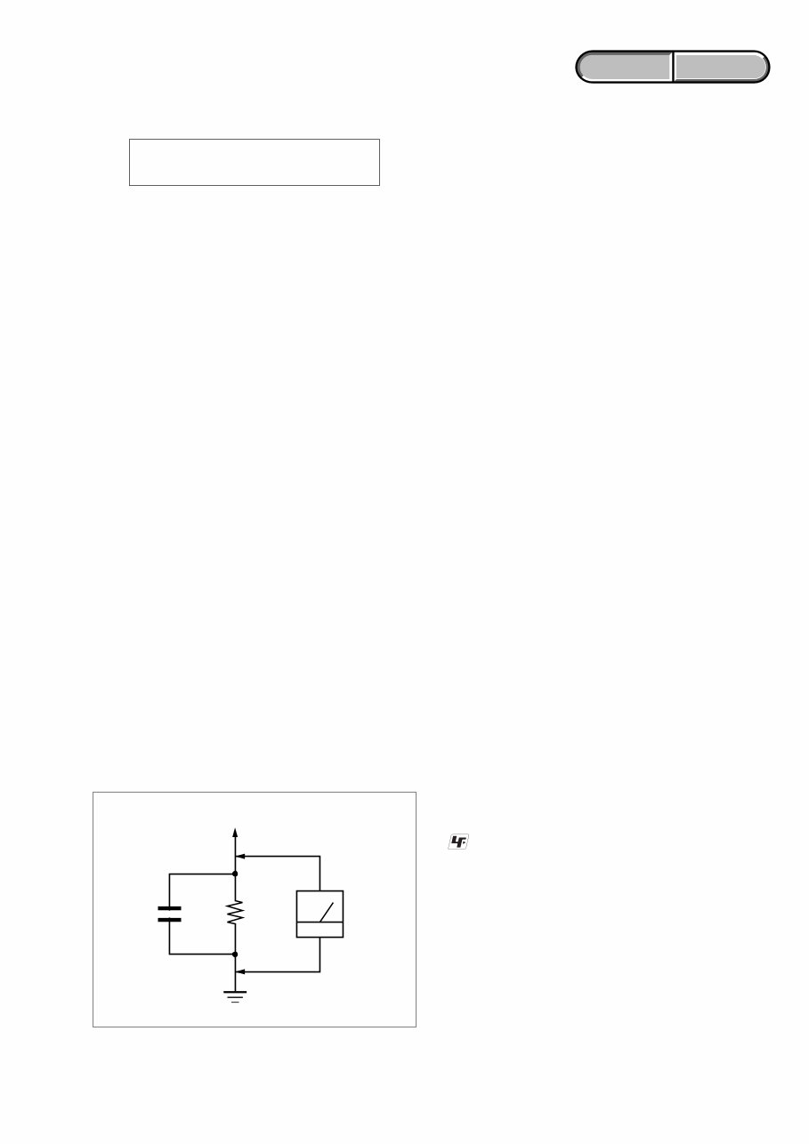
— 5 — HVR-M25J/M25U/M25N/M25E/M25P/M25C ENGLISH JAPANESE ENGLISH JAPANESE SAFETY-RELATED COMPONENT WARNING!! COMPONENTS IDENTIFIED BY MARK 0 OR DOTTED LINE WITH MARK 0 ON THE SCHEMATIC DIAGRAMS AND IN THE PARTS LIST ARE CRITICAL TO SAFE OPERATION. REPLACE THESE COMPONENTS WITH SONY PARTS WHOSE PART NUMBERS APPEAR AS SHOWN IN THIS MANUAL OR IN SUPPLEMENTS PUBLISHED BY SONY. SAFETY CHECK-OUT After correcting the original service problem, perform the following safety checks before releasing the set to the customer. CAUTION Danger of explosion if battery is incorrectly replaced. Replace only with the same or equivalent type. ATTENTION AU COMPOSANT AYANT RAPPORT À LA SÉCURITÉ! LES COMPOSANTS IDENTIFÉS PAR UNE MARQUE 0 SUR LES DIAGRAMMES SCHÉMATIQUES ET LA LISTE DES PIÈCES SONT CRITIQUES POUR LA SÉCURITÉ DE FONCTIONNEMENT. NE REMPLACER CES COMPOSANTS QUE PAR DES PIÈSES SONY DONT LES NUMÉROS SONT DONNÉS DANS CE MANUEL OU DANS LES SUPPÉMENTS PUBLIÉS PAR SONY. 1.5 k Ω 0.15 µF AC Voltmeter (0.75 V) To Exposed Metal Parts on Set Earth Ground 1. Check the area of your repair for unsoldered or poorly-soldered connections. Check the entire board surface for solder splashes and bridges. 2. Check the interboard wiring to ensure that no wires are “pinched” or contact high-wattage resistors. 3. Look for unauthorized replacement parts, particularly transistors, that were installed during a previous repair. Point them out to the customer and recommend their replacement. 4. Look for parts which, though functioning, show obvious signs of deterioration. Point them out to the customer and recommend their replacement. 5. Check the line cord for cracks and abrasion. Recommend the replacement of any such line cord to the customer. 6. Check the B+ voltage to see it is at the values specified. 7. Check the antenna terminals, metal trim, “metallized” knobs, screws, and all other exposed metal parts for AC leakage. Check leakage as described below. UNLEADED SOLDER Boards requiring use of unleaded solder are printed with the lead- free mark (LF) indicating the solder contains no lead. (Caution: Some printed circuit boards may not come printed with the lead free mark due to their particular size) : LEAD FREE MARK Unleaded solder has the following characteristics. • Unleaded solder melts at a temperature about 40 ˚C higher than ordinary solder. Ordinary soldering irons can be used but the iron tip has to be applied to the solder joint for a slightly longer time. Soldering irons using a temperature regulator should be set to about 350 ˚C . Caution: The printed pattern (copper foil) may peel away if the heated tip is applied for too long, so be careful! • Strong viscosity Unleaded solder is more viscous (sticky, less prone to flow) than ordinary solder so use caution not to let solder bridges occur such as on IC pins, etc. • Usable with ordinary solder It is best to use only unleaded solder but unleaded solder may also be added to ordinary solder. LEAKAGE TEST The AC leakage from any exposed metal part to earth ground and from all exposed metal parts to any exposed metal part having a return to chassis, must not exceed 0.5 mA (500 microamperes). Leakage current can be measured by any one of three methods. 1. A commercial leakage tester, such as the Simpson 229 or RCA WT-540A. Follow the manufacturers' instructions to use these instruments. 2. A battery-operated AC milliammeter. The Data Precision 245 digital multimeter is suitable for this job. 3. Measuring the voltage drop across a resistor by means of a VOM or battery-operated AC voltmeter. The “limit” indication is 0.75V, so analog meters must have an accurate low-voltage scale. The Simpson 250 and Sanwa SH-63Trd are examples of a passive VOM that is suitable. Nearly all battery operated digital multimeters that have a 2V AC range are suitable. (See Fig. A) Fig. A Using AC voltmeter to check AC leakage
— 7 — HVR-M25J/M25U/M25N/M25E/M25P/M25C TABLE OF CONTENTS 1. SERVICE NOTE 1- 1. Self-diagnosis Function ··················································· 1-1 2. DISASSEMBLY 2-1. Disassembly ····································································· 2-2 3. BLOCK DIAGRAMS 3-1. Overall Block Diagram (1/7) ··········································· 3-1 3-2. Overall Block Diagram (2/7) ··········································· 3-2 3-3. Overall Block Diagram (3/7) ··········································· 3-3 3-4. Overall Block Diagram (4/7) ··········································· 3-4 3-5. Overall Block Diagram (5/7) ··········································· 3-5 3-6. Overall Block Diagram (6/7) ··········································· 3-6 3-7. Overall Block Diagram (7/7) ··········································· 3-7 3-8. Power Block Diagram (1/3) ············································· 3-8 3-9. Power Block Diagram (2/3) ············································· 3-9 3-10. Power Block Diagram (3/3) ··········································· 3-10 4. PRINTED WIRING BOARDS AND SCHEMATIC DIAGRAMS 4-1. Frame Schematic Diagram ·············································· 4-1 4-2. Schematic Diagrams ························································ 4-3 4-3. Printed Wiring Boards ··················································· 4-31 4-4. Mounted Parts Location ················································ 4-47 5. REPAIR PARTS LIST 5-1. Exploded Views ·······························································5-2 5-2. Electrical Parts List ······················································· 5-11 Section Title P age 6. ADJUSTMENTS Before Starting Adjustments ····················································· 6-1 1-1. Adjusting Items when Replacing Main Parts and Boards ·············································································· 6-2 1-2. List of Service Tools ························································6-3 1-3. Information (Mechanical Section) ··································· 6-5 6-1. Mechanical Section Adjustments ···································· 6-6 6-1-1. Parts Replacement and Preparation for Adjustment ········ 6-6 6-1-2. Periodic Check ································································ 6-8 6-1-3. Parts Replacement ··························································· 6-9 6-1-4. Check and Adjustment ·················································· 6-23 6-2. Video Section Adjustments ··········································· 6-32 2-1. Preparations before Adjustments ··································· 6-32 2-2. Initialization of 8, 9, A, B, C, D, 13, 18, 1A, 1B, 1C, 1D Page Data ································································· 6-35 2-3. System Control System Adjustments ···························· 6-40 2-4. Servo and RF System Adjustments ······························· 6-42 2-5. Video System Adjustments ············································6-45 2-6. LCD System Adjustments ············································· 6-55 2-7. Audio System Adjustments ··········································· 6-58 6-3. Service Mode ································································· 6-65 3-1. Adjustment Remote Commander (RM-95) ··················· 6-65 3-2. Adjustment Remote Commander (New LANC Jig) ····· 6-66 3-3. Data Process ·································································· 6-67 3-4. Service Mode ································································· 6-68 Section Title P age
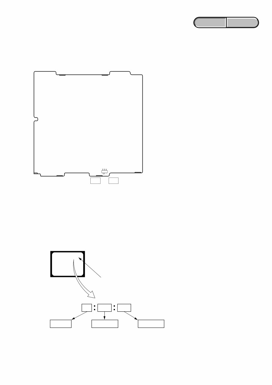
1-1 HVR-M25J/M25U/M25N/M25E/M25P/M25C ENGLISH JAPANESE ENGLISH JAPANESE 1. SERVICE NOTE 1-2-1. Self-diagnosis Function When problems occur while the unit is operating, the self-diagnosis function starts working, and displays on the LCD monitor what to do. Details of the self-diagnosis functions are provided in the Instruction manual. 1-2-2. Self-diagnosis Display When problems occur while the unit is operating, the time code of the LCD monitor shows a 4-digit display consisting of an alphabet and numbers, which blinks at 3.2 Hz. This 5-character display indicates the “repaired by:”, “block” in which the problem occurred, and “detailed code” of the problem. 1 1 3 1 C Repaired by: Refer to “1-2-3. Self-diagnosis Code Table”. Indicates the appropriate step to be taken. E.g. 31 ....Reload the tape. 32 ....Turn on power again. Block Detailed Code Blinks at 3.2Hz C : Corrected by customer H : Corrected by dealer E : Corrected by service engineer LCD monitor C : 3 1 : 1 1 1-2. SELF-DIAGNOSIS FUNCTION 1-1. PRECAUTION ON REPLACING THE VD-036 BOARD Set S4602 of the VD-036 board to the following position. Switch setting S4602 ...................................... 60i (HVR-M25J/M25U/M25N)/50i (HVR-M25E/M25P/M25C) S4602 60i t 50i VD-036 BOARD (SIDE B)
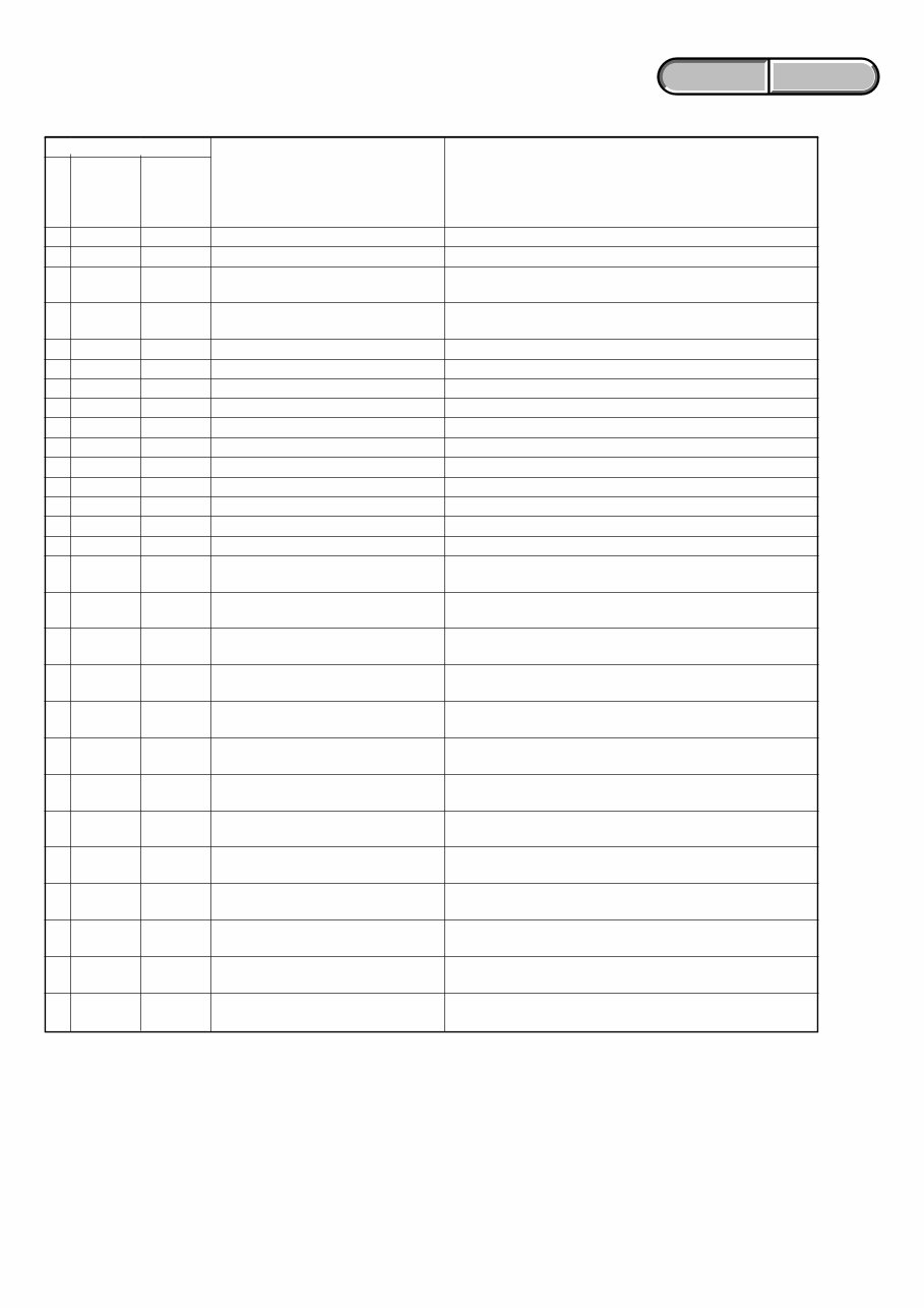
1-2 HVR-M25J/M25U/M25N/M25E/M25P/M25C ENGLISH JAPANESE ENGLISH JAPANESE 1-2-3. Self-diagnosis Code Table C C C C C C C C C C C C C C C C C C C C C C C C C C C C Block Function 2 1 2 2 3 1 3 1 3 1 3 1 3 1 3 1 3 1 3 1 3 1 3 1 3 1 3 1 3 1 3 2 3 2 3 2 3 2 3 2 3 2 3 2 3 2 3 2 3 2 3 2 3 2 3 2 Detailed Code 0 0 0 0 1 0 1 1 2 0 2 1 2 2 2 3 3 0 3 1 4 0 4 1 4 2 4 3 4 4 1 0 1 1 2 0 2 1 2 2 2 3 3 0 3 1 4 0 4 1 4 2 4 3 4 4 Symptom/State Condensation. Video head is dirty. LOAD direction. Loading does not complete within specified time UNLOAD direction. Loading does not complete within specified time T reel side tape slacking when unloading. S reel side tape slacking when unloading. T reel fault. S reel fault. FG fault when starting capstan. FG fault during normal capstan operations. FG fault when starting drum. PG fault when starting drum. FG fault during normal drum operations. PG fault during normal drum operations. Phase fault during normal drum operations. LOAD direction loading motor time- out. UNLOAD direction loading motor time-out. T reel side tape slacking when unloading. S reel side tape slacking when unloading. T reel fault. S reel fault. FG fault when starting capstan. FG fault during normal capstan operations. FG fault when starting drum. PG fault when starting drum. FG fault during normal drum operations. PG fault during normal drum operations. Phase fault during normal drum operations. Self-diagnosis Code Repaired by: Correction Remove the cassette, and insert it again after one hour. Clean with the optional cleaning cassette. Load the tape again, and perform operations from the beginning. Load the tape again, and perform operations from the beginning. Load the tape again, and perform operations from the beginning. Load the tape again, and perform operations from the beginning. Load the tape again, and perform operations from the beginning. Load the tape again, and perform operations from the beginning. Load the tape again, and perform operations from the beginning. Load the tape again, and perform operations from the beginning. Load the tape again, and perform operations from the beginning. Load the tape again, and perform operations from the beginning. Load the tape again, and perform operations from the beginning. Load the tape again, and perform operations from the beginning. Load the tape again, and perform operations from the beginning. Remove the power cable, connect, and perform operations from the beginning. Remove the power cable, connect, and perform operations from the beginning. Remove the power cable, connect, and perform operations from the beginning. Remove the power cable, connect, and perform operations from the beginning. Remove the power cable, connect, and perform operations from the beginning. Remove the power cable, connect, and perform operations from the beginning. Remove the power cable, connect, and perform operations from the beginning. Remove the power cable, connect, and perform operations from the beginning. Remove the power cable, connect, and perform operations from the beginning. Remove the power cable, connect, and perform operations from the beginning. Remove the power cable, connect, and perform operations from the beginning. Remove the power cable, connect, and perform operations from the beginning. Remove the power cable, connect, and perform operations from the beginning.
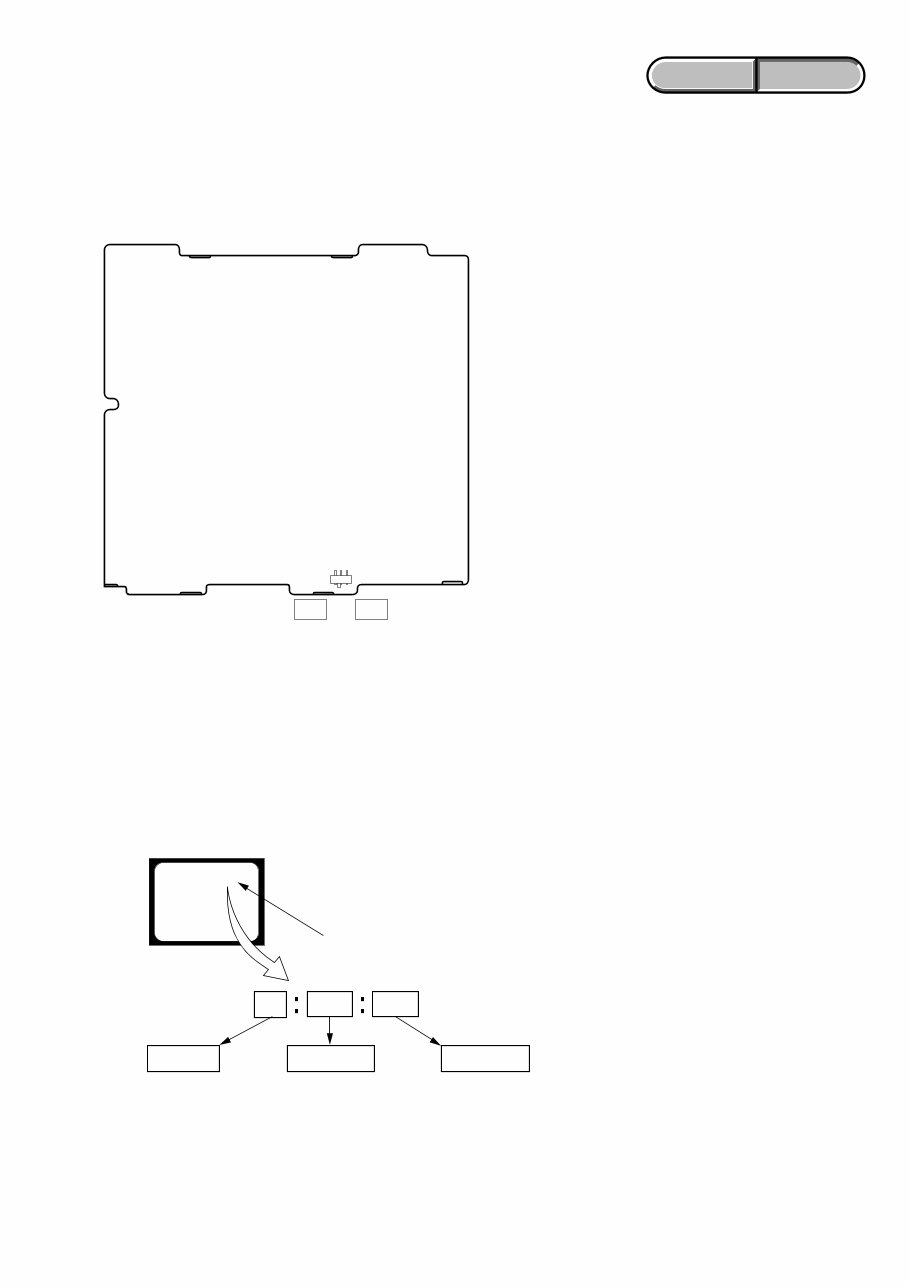
1-3 HVR-M25J/M25U/M25N/M25E/M25P/M25C ENGLISH JAPANESE ENGLISH JAPANESE 1. SERVICE NOTE VD-036基板のS4602は,次のように設定してください。 スイッチ設定 S4602 ...................................... 60i(HVR-M25J/M25U/M25N)/50i(HVR-M25E/M25P/M25C) 1-1. VD-036基板交換時の注意 1-2-1. 自己診断機能について 本機の動作に不具合が生じたとき,自己診断機能が働き, L C D モニタに,どう処置したらよいか判断できる表示を行 います。自己診断機能については取扱説明書にも掲載され ています。 1-2. 自己診断機能 1-2-2. 自己診断表示 本機の動作に不具合が生じたとき,L C D モニタのタイムコー ド表示部分がアルファベットと数字の4 桁表示になり,3 . 2 H z で点滅します。この5 文字の表示によって対応者分類および 不具合の生じたブロックの分類,不具合の詳細コードを示し ます。 1 1 3 1 C 対応者分類 「1-2-3. 自己診断コード表」 を参照 対応方法の違いにより分類 例 31・・・テープを入れ直す 32・・・電源を入れ直す ブロック分類 詳細コード 3.2Hz点滅 C :お客さま自身で対応 H :販売店で対応 E :サービスエンジニア で対応 LCDモニタ C : 3 1 : 1 1 S4602 60i t 50i VD-036 BOARD (SIDE B)
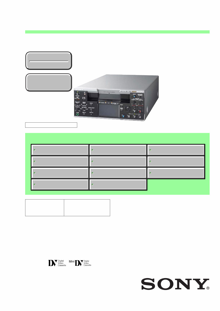
Is your Sony HVR-M25 HDV/DVCAM/DV-SP Player/Recorder causing you trouble? Don't rush to replace it – consider upgrading or repairing it yourself with the help of this comprehensive service and repair manual. This manual is the same one used by Official Certified Sony Technicians and is designed to assist you in troubleshooting and fixing your HDV/DVCAM/DV-SP Player/Recorder.
Contents:
Service Note
Self-Diagnosis Function
Disassembly Instructions
Disassembly
Block Diagrams
Overall Block Diagram
Power Block Diagram
Printed Wiring Boards and Schematic Diagrams
Frame Schematic Diagram
Schematic Diagrams
Printed Wiring Boards
Mounted Parts Location
Repair Parts List
Exploded Views
Electrical Parts List
Adjustments
Adjusting Items when Replacing Main Parts and Boards
List Of Service Tools
Information (Mechanical Section)
Mechanical Section Adjustments
Parts Replacement And Preparation For Adjust
Periodic Check
Parts Replacement
Check And Adjustment
Video Section Adjustments
Preparations Before Adjustments
Initialization Page Data
System Control System Adjustments
Servo And Rf System Adjustments
Video System Adjustments
Lcd System Adjustments
Audio System Adjustments
Service Mode
Adjustment Remote Commander (Rm-95)
Adjustment Remote Commander (New Lanc Jig)
Data Process
Service Mode
This manual covers all HVR-M25 models:
Sony HVR-M25J
Sony HVR-M25U
Sony HVR-M25N
Sony HVR-M25E
Sony HVR-M25P
Sony HVR-M25C
This detailed service manual is illustrated with pictures and step-by-step instructions to guide you through the repair/service process effectively. It is the official service and repair manual in PDF format, ensuring the highest resolution for quality printing from any printer and computer.
With instant access after payment, there are no shipping fees or waiting for postal delivery, allowing you to start your repairs immediately. The manual is available in English and is compatible with Windows and MAC platforms.
If you're looking for a service manual that's not readily available, feel free to contact us with your request. With the largest and most comprehensive service manual database, we may be able to assist you!