

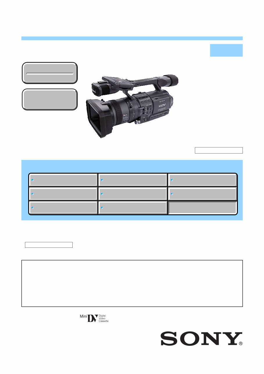
HDR-FX1
US Model
Canadian Model
Korea Model
Japanese Model
HDR-FX1E
AEP Model
UK Model
Australian Model
Chinese Model
Hong Kong Model
HDR-FX1/FX1E
E Model
Tourist Model
SERVICE MANUAL
DIGITAL HD VIDEO CAMERA RECORDER
LEVEL 2
• For ADJUSTMENTS (SECTION 6), refer to SERVICE MANUAL, ADJ (987677051.pdf).
• For INSTRUCTION MANUAL, refer to SERVICE MANUAL, LEVEL 1 (987677041.pdf). (EXCEPT J MODEL)
• For MECHANISM ADJUSTMENTS, refer to the “DV MECHANICAL ADJUSTMENT MANUAL VIII
Z (Z310) MECHANISM ” (EXCEPT J: 9-876-724-12) (J: 9-876-724-02).
• Reference number search on printed wiring boards is available.
• TO TAKE OUT A CASSETTE WHEN NOT EJECT (FORCE EJECT)
Link
SERVICE NOTE
DISASSEMBLY
BLOCK DIAGRAMS
FRAME SCHEMATIC DIAGRAMS
SCHEMATIC DIAGRAMS
PRINTED WIRING BOARDS
REPAIR PARTS LIST
SPECIFICATIONS
SERVICE NOTE
DISASSEMBLY
BLOCK DIAGRAMS
FRAME SCHEMATIC DIAGRAMS
SCHEMATIC DIAGRAMS
PRINTED WIRING BOARDS
REPAIR PARTS LIST
SPECIFICATIONS
Link
Revision History Revision History
Ver. 1.7 2008. 09
On the CD-522, DA-033, DB-018 and VC-367 board
This service manual provides the information that is premised the circuit board replacement service and not intended repair
inside the CD-522, DA-033, DB-018 and VC-367 board.
Therefore, schematic diagram, printed wiring board, waveforms, mounted parts location and electrical parts list of the CD-522,
DA-033, DB-018 and VC-367 board are not shown.
The following pages are not shown.
Mounted parts location ....................... Pages 4-173 to 4-177
Electrical parts list .............................. Pages 5-31 to 5-50
How to use
Acrobat Reader
How to use
Acrobat Reader
Schematic diagram ............................. Pages 4-53 to 4-110
Printed wiring board ............................ Pages 4-151 to 4-166
Waveforms ........................................... Pages 4-169 to 4-170
Sony EMCS Co.
2008I0800-1
©2008.09
Published by Kohda TEC 9-876-770-31
HDR-FX1/FX1E
RMT-840
HDR-FX1/FX1E
Photo : HDR-FX1
Z (Z310) MECHANISM

— 2 —
HDR-FX1/FX1E
SPECIFICATIONS
ENGLISH JAPANESE ENGLISH JAPANESE
System
Video recording system (HDV)
2 rotary heads, Helical scanning system
Video recording system (DV)
2 rotary heads, Helical scanning system
Audio recording system (HDV)
Rotary heads, MPEG-1 Audio Layer2
Quantization: 16 bits (Fs 48 kHz, stereo)
Transfer rate: 384 kbps
Audio recording system (DV)
Rotary heads, PCM system
Quantization: 12 bits (Fs 32 kHz, stereo 1,
stereo 2), 16 bits (Fs 48 kHz, stereo)
Video signal
N
HDR-FX1:
TSC color, EIA standards, 1080/60i
specification
HDR-FX1E:
Usable cassette
Mini DV cassette with the mark
printed
Tape speed (HDV)
Approx. 18.81 mm/s
Tape speed (DV)
SP: Approx. 18.81 mm/s
LP: Approx. 12.56 mm/s
Recording/playback time (HDV)
60 min (using a DVM60 cassette)
Recording/playback time (DV)
SP: 60 min (using a DVM60 cassette)
LP: 90 min (using a DVM60 cassette)
Fast forward/rewind time
Approx. 2 min 40 s (using a DVM60 cassette)
Viewfinder
Electric viewfinder (color)
Image device
6 mm (1/3 type) 3CCD (Charge Coupled
Device)
Gross: Approx. 1 120 000 pixels
Effective: Approx. 1 070 000 pixels
Lens
Carl Zeiss Vario-Sonnar T*
Combined power zoom lens
Filter diameter: 72 mm (2 7/8 in.)
12 (O ptical)
F = 1.6 ~ 2.8
Focal length
4.5 - 54 mm (3/16 - 2 1/4 in.)
When converted to a 35 mm still camera
32.5 - 390 mm (1 5/16 - 15 3/8 in.)
(40 - 480 mm (1 5/8 - 19 in.) in 4:3 TV mode)
Color temperature
[AUTO], [ONE-PUSH A/B], [INDOOR]
(3 200 K), [OUTDOOR] (5 800 K)
Minimum illumination
3 lx (lux) (F 1.6)
Input/Output connectors
Audio/Video input/output
Video signal: 1 Vp-p, 75 Ω (ohms),
unbalanced, sync negative
Audio signal: 327 mV (at load impedance
47 kΩ (kilohms)), Input impedance more than
47 kΩ (kilohms), Output impedance less than
2.2 kΩ (kilohms)
S VIDEO input/output
Luminance signal: 1 Vp-p, 75 Ω (ohms),
un
HDR-FX1:
balanced
Chrominance signal: 0.286 Vp-p, 75 Ω
(ohms), unbalanced
HDR-FX1E:
COMPONENT OUTPUT jack
Y: 1 Vp-p (0.3 V sync negative)
PB/PR, CB/CR: +/- 350 mVp-p, Input
impedance 75 Ω (ohms)
Headphones jack
Stereo minijack (Ø 3.5 mm)
LANC jack
Stereo mini-minijack (Ø 2.5 mm)
MIC jack
Minijack, 0.388 mV low impedance with DC
2.5 to 3.0 V, output impedance 6.8 kΩ
(kilohms) (Ø 3.5 mm), Stereo type
HDV/DV jack
i.LINK Interface (IEEE1394, 4-pin connector
S100)
LCD screen
Picture
8.8 cm (3.5 type)
Total dot number
250 000 (1 120 × 224)
General
Power requirements
DC 7.2 V (battery pack)
DC 8.4 V (AC Adaptor)
Average power consumption (when using the
battery pack)
During camera recording using the viewfinder
w
HDR-FX1:
ith normal brightness:
HDV recording 7.4 W
DV recording 6.9 W
HDR-FX1E:
During camera recording using the LCD with
normal brightness:
H
HDR-FX1:
DV recording 8.0 W
DV recording 7.5 W
HDR-FX1E:
Operating temperature
0°C to 40°C (32°F to 104°F)
Storage temperature
-20°C to + 60°C (-4°F to + 140°F)
Dimensions (approx.)
151 × 181 × 365 mm (6 × 7 1/4 × 14 3/8 in.)
(w/h/d)
Mass (Approx.)
2.0 kg (4 lb 6 1/2 oz) main unit only
2.1 kg (4 lb 10 1/8 oz) including the NP-F570
rechargeable battery pack, DVM60 cassette
and lens hood.
Supplied accessories
See page 5-19.
AC Adaptor AC-L15A/L15B
Power requirements
AC 100 - 240 V, 50/60 Hz
Current consumption
0.35 - 0.18 A
Power consumption
18 W
Output voltage
DC 8.4 V, 1.5 A
Operating temperature
0°C to 40°C (32°F to 104°F)
Storage temperature
-20°C to + 60°C (-4°F to + 140°F)
Dimensions (approx.)
56 × 31 × 100 mm (2 1/4 × 1 1/4 × 4 in.) (w/h/
d) excluding the projecting parts
Mass (approx.)
190 g (6.7 oz) excluding the power cord
Rechargeable battery pack (NP-F570)
Maximum output voltage
DC 8.4 V
Output voltage
DC 7.2 V
Capacity
15.8 Wh (2 200 mAh)
Dimensions (approx.)
38.4 × 20.6 × 70.8 mm
(1 9/16 × 13/16 × 2 7/8 in.) (w/h/d)
Mass (approx.)
100 g (3.5 oz)
Operating temperature
0°C to 40°C (32°F to 104°F)
Type
Lithium ion
Design and specifications are subject to ch
without notice.
PAL color, CCIR standards, 1080/50i
specification
Chrominance signal: 0.3 Vp-p, 75 Ω (ohms),
unbalanced
HDV recording 7.3 W
DV recording 6.9 W
HDV recording 7.9 W
DV recording 7.5 W

— 3 —
HDR-FX1/FX1E
ENGLISH JAPANESE ENGLISH JAPANESE
✄
✄
✄
✄
✄✄
— 4 —
HDR-FX1/FX1E
ENGLISH JAPANESE ENGLISH JAPANESE
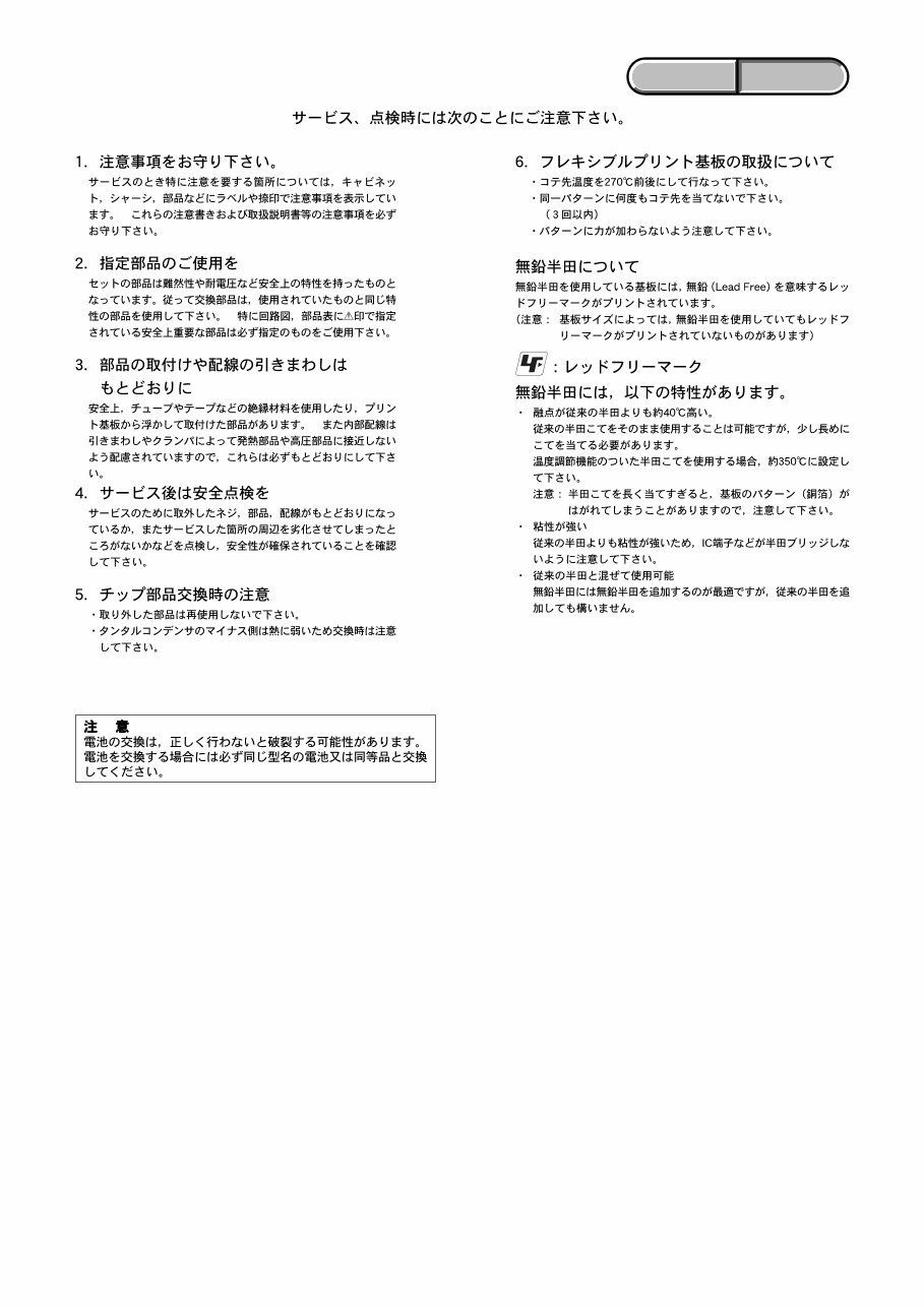
1. Check the area of your repair for unsoldered or poorly-soldered
connections. Check the entire board surface for solder splashes
and bridges.
2. Check the interboard wiring to ensure that no wires are
"pinched" or contact high-wattage resistors.
3. Look for unauthorized replacement parts, particularly
transistors, that were installed during a previous repair. Point
them out to the customer and recommend their replacement.
4. Look for parts which, through functioning, show obvious signs
of deterioration. Point them out to the customer and
recommend their replacement.
5. Check the B+ voltage to see it is at the values specified.
6. Flexible Circuit Board Repairing
• Keep the temperature of the soldering iron around 270˚C
during repairing.
• Do not touch the soldering iron on the same conductor of the
circuit board (within 3 times).
• Be careful not to apply force on the conductor when soldering
or unsoldering.
Unleaded solder
Boards requiring use of unleaded solder are printed with the lead-
free mark (LF) indicating the solder contains no lead.
(Caution: Some printed circuit boards may not come printed with
the lead free mark due to their particular size.)
: LEAD FREE MARK
Unleaded solder has the following characteristics.
• Unleaded solder melts at a temperature about 40°C higher than
ordinary solder.
Ordinary soldering irons can be used but the iron tip has to be
applied to the solder joint for a slightly longer time.
Soldering irons using a temperature regulator should be set to
about 350°C.
Caution: The printed pattern (copper foil) may peel away if the
heated tip is applied for too long, so be careful!
• Strong viscosity
Unleaded solder is more viscous (sticky, less prone to flow) than
ordinary solder so use caution not to let solder bridges occur such
as on IC pins, etc.
• Usable with ordinary solder
It is best to use only unleaded solder but unleaded solder may
also be added to ordinary solder.
SAFETY CHECK-OUT
After correcting the original service problem, perform the following
safety checks before releasing the set to the customer.
SAFETY-RELATED COMPONENT WARNING!!
COMPONENTS IDENTIFIED BY MARK 0 OR DOTTED LINE WITH
MARK 0 ON THE SCHEMATIC DIAGRAMS AND IN THE PARTS
LIST ARE CRITICAL TO SAFE OPERATION. REPLACE THESE
COMPONENTS WITH SONY PARTS WHOSE PART NUMBERS
APPEAR AS SHOWN IN THIS MANUAL OR IN SUPPLEMENTS
PUBLISHED BY SONY.
ATTENTION AU COMPOSANT AYANT RAPPORT
À LA SÉCURITÉ!
LES COMPOSANTS IDENTIFÉS PAR UNE MARQUE 0 SUR LES
DIAGRAMMES SCHÉMATIQUES ET LA LISTE DES PIÈCES SONT
CRITIQUES POUR LA SÉCURITÉ DE FONCTIONNEMENT. NE
REMPLACER CES COMPOSANTS QUE PAR DES PIÈSES SONY
DONT LES NUMÉROS SONT DONNÉS DANS CE MANUEL OU
DANS LES SUPPÉMENTS PUBLIÉS PAR SONY.
CAUTION :
Danger of explosion if battery is incorrectly replaced.
Replace only with the same or equivalent type.
— 5 —
HDR-FX1/FX1E
ENGLISH JAPANESE ENGLISH JAPANESE

— 6 —
HDR-FX1/FX1E
TABLE OF CONTENTS
1. SERVICE NOTE
1-1. SERVICE NOTE ·····························································1-1
1. NOTE FOR REPAIR ·······················································1-1
2. POWER SUPPLY DURING REPAIRS ··························1-2
3. TO TAKE OUT A CASSETTE WHEN NOT EJECT
(FORCE EJECT) ····························································· 1-2
1-2. SELF-DIAGNOSIS FUNCTION ···································· 1-3
1. SELF-DIAGNOSIS FUNCTION ···································· 1-3
2. SELF-DIAGNOSIS DISPLAY ······································· 1-3
3. SELF-DIAGNOSIS CODE TABLE ································1-4
2. DISASSEMBLY
2-1. DISASSEMBLY ······························································2-1
2-2. SERVICE POSITION ····················································· 2-7
2-3. CIRCUIT BOARDS LOCATION ·································2-10
2-4. FLEXIBLE BOARDS LOCATION ······························2-12
3. BLOCK DIAGRAMS
3-1. OVERALL BLOCK DIAGRAM (1/6) ···························3-1
3-2. OVERALL BLOCK DIAGRAM (2/6) ···························3-3
3-3. OVERALL BLOCK DIAGRAM (3/6) ···························3-5
3-4. OVERALL BLOCK DIAGRAM (4/6) ···························3-7
3-5. OVERALL BLOCK DIAGRAM (5/6) ···························3-9
3-6. OVERALL BLOCK DIAGRAM (6/6) ·························3-11
3-7. POWER BLOCK DIAGRAM (1/4) ······························3-13
3-8. POWER BLOCK DIAGRAM (2/4) ······························3-15
3-9. POWER BLOCK DIAGRAM (3/4) ······························3-17
3-10. POWER BLOCK DIAGRAM (4/4) ······························3-19
4. PRINTED WIRING BOARDS AND
SCHEMATIC DIAGRAMS
4-1. FRAME PRINTED WIRING BOARD (1/2) ·················· 4-1
FRAME PRINTED WIRING BOARD (2/2) ·················· 4-3
4-2. SCHEMATIC DIAGRAMS
• CK-143 (FUNCTION KEY)
SCHEMATIC DIAGRAMS ····························4-7
• FP-962 FLEXIBLE BOARD (IRIS DIAL)
SCHEMATIC DIAGRAM ······························4-7
• FP-963 FLEXIBLE BOARD (WB/GAIN SW)
SCHEMATIC DIAGRAM ······························4-7
• FP-965 FLEXIBLE BOARD (LID SW)
SCHEMATIC DIAGRAM ······························4-7
• FK-090 (VTR FUNCTION KEY)
SCHEMATIC DIAGRAM ······························4-9
• IF-122 (RELAY)
SCHEMATIC DIAGRAM ····························4-11
• FP-967 FLEXIBLE BOARD (MR SENSOR)
SCHEMATIC DIAGRAM ····························4-11
• SW-433 (PANEL REV)
SCHEMATIC DIAGRAM ····························4-11
• JK-274 (JACK)
SCHEMATIC DIAGRAM ····························4-13
• LB-106 (EVF BACK LIGHT)
SCHEMATIC DIAGRAM ····························4-15
• MA-431 (INT MIC AMP)
SCHEMATIC DIAGRAM ····························4-17
• MK-017 (FUNCTION KEY)
SCHEMATIC DIAGRAM ····························4-19
• CONTROL SWITCH BLOCK (VS-5610)
SCHEMATIC DIAGRAM ····························4-19
• FP-966 FLEXIBLE BOARD (AUTO LOCK)
SCHEMATIC DIAGRAM ····························4-19
• MR-048 (1/2) (REC/PB RF AMP)
SCHEMATIC DIAGRAM ····························4-21
• MR-048 (2/2) (DRUM/CAPSTAN/LOADING MOTOR
DRIVE)
SCHEMATIC DIAGRAM ····························4-23
• PD-222 (LCD DRIVER, TIMING GENERATOR)
SCHEMATIC DIAGRAM ····························4-25
• SE-150 (PITCH/YAW SENSOR AMP)
SCHEMATIC DIAGRAM ····························4-27
• VA-119 (1/3) (AUDIO IN/OUT)
SCHEMATIC DIAGRAM ····························4-29
• VA-119 (2/3) (VIDEO IN/OUT)
SCHEMATIC DIAGRAM ····························4-31
• VA-119 (3/3) (Y. PB. PR. OUT AMP)
SCHEMATIC DIAGRAM ····························4-33
• FP-975 FLEXIBLE BOARD (RELAY)
SCHEMATIC DIAGRAM ····························4-35
• FP-980 FLEXIBLE BOARD (RELAY, REAR IR)
SCHEMATIC DIAGRAM ····························4-35
• CONTROL SWITCH BLOCK (ZS-5610)
SCHEMATIC DIAGRAM ····························4-35
• FP-959 FLEXIBLE BOARD (BATTERY)
SCHEMATIC DIAGRAM ····························4-37
• FP-961 FLEXIBLE BOARD (FUNCTION KEY, TALLY)
SCHEMATIC DIAGRAM ····························4-37
• FP-977 FLEXIBLE BOARD (RELAY)
SCHEMATIC DIAGRAM ····························4-39
• FP-964 FLEXIBLE BOARD (DV TERMINAL)
SCHEMATIC DIAGRAM ····························4-41
• FP-971 FLEXIBLE BOARD (RELAY)
SCHEMATIC DIAGRAM ····························4-43
• FP-976 FLEXIBLE BOARD (RELAY)
SCHEMATIC DIAGRAM ····························4-45
• FP-981 FLEXIBLE BOARD (RELAY)
SCHEMATIC DIAGRAM ····························4-47
• CONTROL SWITCH BLOCK (CF5610)
SCHEMATIC DIAGRAM ····························4-49
• CONTROL SWITCH BLOCK (PS5610)
SCHEMATIC DIAGRAM ····························4-49
• FP-228/467/826 FLEXIBLE BOARD
SCHEMATIC DIAGRAM ····························4-51
Shematic diagram of the CD-522, DA-033, DB-018 and
VC-367 board are not shown.
Pages from 4-53 to 4-110 are not shown.
• FP-972 FLEXIBLE BOARD (RELAY)
SCHEMATIC DIAGRAM ··························4-111
• FP-974 FLEXIBLE BOARD (RELAY)
SCHEMATIC DIAGRAM ··························4-113
4-3. PRINTED WIRING BOARDS
• CK-143 (FUNCTION KEY)
PRINTED WIRING BOARD ····················· 4-117
• FK-090 (VTR FUNCTION KEY)
PRINTED WIRING BOARD ····················· 4-119
• FP-964 FLEXIBLE (DV TERMINAL)
PRINTED WIRING BOARD ····················· 4-121
• FP-971 FLEXIBLE (RELAY)
PRINTED WIRING BOARD ····················· 4-121
• FP-967 FLEXIBLE (MR SENSOR)
PRINTED WIRING BOARD ····················· 4-122
• FP-975 FLEXIBLE (RELAY)
PRINTED WIRING BOARD ····················· 4-122
• FP-959 FLEXIBLE (BATTERY)
PRINTED WIRING BOARD ····················· 4-123
• FP-980 FLEXIBLE (RELAY, REAR IR)
PRINTED WIRING BOARD ····················· 4-123
• FP-976 FLEXIBLE (RELAY)
PRINTED WIRING BOARD ····················· 4-124
• FP-981 FLEXIBLE (RELAY)
PRINTED WIRING BOARD ····················· 4-124
• FP-977 FLEXIBLE (RELAY)
PRINTED WIRING BOARD ····················· 4-125
— 7 —
HDR-FX1/FX1E
• IF-122 (RELAY)
PRINTED WIRING BOARD ·····················4-127
• JK-274 (JACK)
PRINTED WIRING BOARD ·····················4-129
• FP-972 FLEXIBLE BOARD (RELAY)
PRINTED WIRING BOARD ·····················4-129
• LB-106 (EVF BACK LIGHT)
PRINTED WIRING BOARD ·····················4-131
• FP-974 FLEXIBLE BOARD (RELAY)
PRINTED WIRING BOARD ·····················4-131
• MA-431 (INT MIC AMP)
PRINTED WIRING BOARD ·····················4-133
• MK-017 (FUNCTION KEY)
PRINTED WIRING BOARD ·····················4-135
• FP-228/467/826 FLEXIBLE
PRINTED WIRING BOARD ·····················4-135
• MR-048 (REC/PB RF AMP, DRUM/CAPSTAN/
LOADING MOTOR DRIVE)
PRINTED WIRING BOARD ·····················4-137
• PD-222 (LCD DRIVER, TIMING GENERATOR)
PRINTED WIRING BOARD ·····················4-141
• SE-150 (PITCH/YAW SENSOR AMP)
PRINTED WIRING BOARD ·····················4-145
• SW-433 (PANEL REV)
PRINTED WIRING BOARD ·····················4-145
• VA-119 (AUDIO IN/OUT, VIDEO IN/OUT, Y. PB. PR.
OUT AMP)
PRINTED WIRING BOARD ·····················4-147
Printed wiring board of the CD-522, DA-033, DB-018
and VC-367 board are not shown.
Pages from 4-151 to 4-166 are not shown.
4-4. WAVEFORMS ····························································4-167
Waveforms of the CD-522, DA-033, DB-018 and
VC-367 board are not shown.
Pages from 4-169 to 4-170 are not shown.
4-5. MOUNTED PARTS LOCATION ·······························4-171
Mounted parts location of the CD-522, DA-033,
DB-018 and VC-367 board are not shown.
Pages from 4-173 to 4-177 are not shown.
5. REPAIR PARTS LIST
5-1-1.OVERALL SECTION ····················································· 5-3
5-1-2. CABINET (R) SECTION-1 ············································ 5-4
5-1-3. CABINET (R) SECTION-2 ············································ 5-5
5-1-4. CABINET (L) SECTION ················································ 5-6
5-1-5. HANDLE SECTION-1 ··················································· 5-7
5-1-6. HANDLE SECTION-2 ··················································· 5-8
5-1-7. LCD SECTION ······························································· 5-9
5-1-8. EVF SECTION ······························································ 5-10
5-1-9. CENTER SECTION ······················································ 5-11
5-1-10. MAIN BOARD SECTION (VA, VC, DA, DB)··········5-12
5-1-11. LENS SECTION ························································ 5-13
5-1-12. TERMINAL CABINET SECTION ···························· 5-14
5-1-13. BATTERY SECTION AND DV SECTION ···············5-15
5-1-14. MECHANISM DECK OVERALL (Z310) ················ 5-16
5-1-15. LS CHASSIS BLOCK ASSEMBLY ··························5-17
5-1-16. MECHANICAL CHASSIS BLOCK ASSEMBLY ····5-18
Checking supplied accessories ················································ 5-19
5-2. ELECTRICAL PARTS LIST ········································5-21
Electrical parts list of the CD-522, DA-033, DB-018
and VC-367 board are not shown.
Pages from 5-31 to 5-50 are not shown.
1-1
HDR-FX1/FX1E
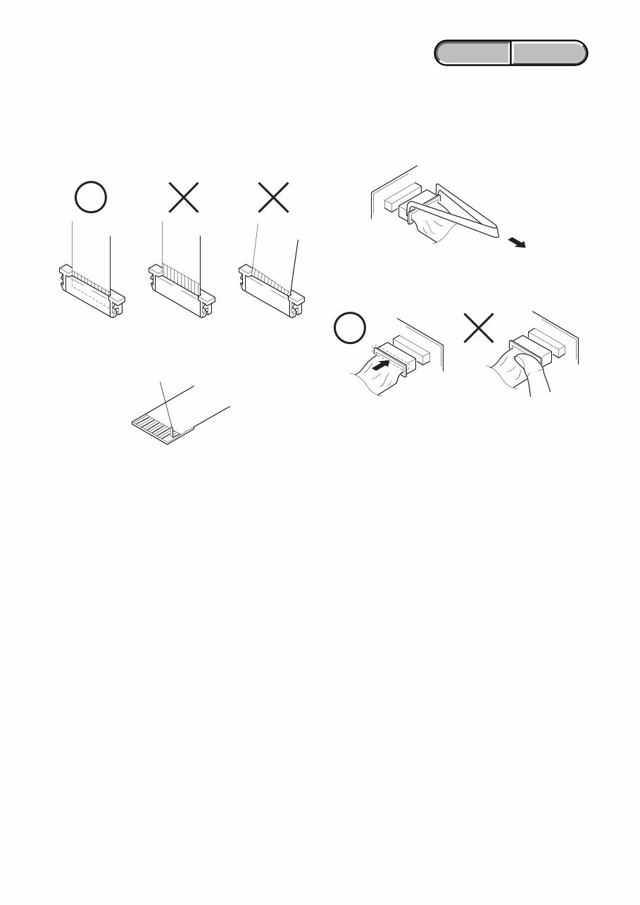
Make sure that the flat cable and flexible board are not cracked of
bent at the terminal.
Do not insert the cable insufficiently nor crookedly.
Cut and remove the part of gilt
which comes off at the point.
(Take care that there are
some pieces of gilt left inside)
When remove a connector, don't pull at wire of connector.
Be in danger of the snapping of a wire.
When installing a connector, don't press down at wire of connector.
Be in danger of the snapping of a wire.
1-1. SERVICE NOTE
1. NOTE FOR REPAIR
ENGLISH JAPANESE ENGLISH JAPANESE
1. SERVICE NOTE
1-2
HDR-FX1/FX1E
ENGLISH JAPANESE ENGLISH JAPANESE
2. POWER SUPPLY DURING REPAIRS
In this unit, about 10 seconds after power is supplied to the battery terminal using the regulated power supply (8.4V), the power is shut off so
that the unit cannot operate.
This following two methods are available to prevent this. Take note of which to use during repairs.
Method 1.
Use the AC power adaptor (AC-L15, AC-VQ800 etc.).
Method 2.
Connect the servicing remote commander RM-95 (J-6082-053-B) to the LANC jack, and set the commander switch to the “ADJ” side.
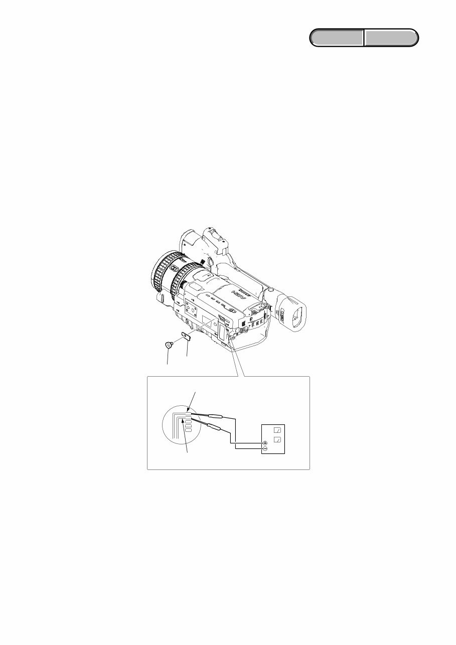
3. TO TAKE OUT A CASSETTE WHEN NOT EJECT (FORCE EJECT)
1 Remove the power supply (Battery and AC power adaptor).
2 Open the cassette lid.
3 Remove the MD lid.
4 Supply +4.5V between the LM UNLOAD terminal and the LM LOAD terminal from the DC power supply and unload the cassete.
DC power supply
(+4.5V)
LM load
LM unload
MD lid
Screw (M2x4)
1-3
HDR-FX1/FX1E
ENGLISH JAPANESE ENGLISH JAPANESE
1-2. SELF-DIAGNOSIS FUNCTION
1. SELF-DIAGNOSIS FUNCTION
When problems occur while the unit is operating, the self-diagnosis
function starts working, and displays on the viewfinder, or LCD
screen what to do.
Details of the self-diagnosis functions are provided in the Instruction
manual.
2. SELF-DIAGNOSIS DISPLAY
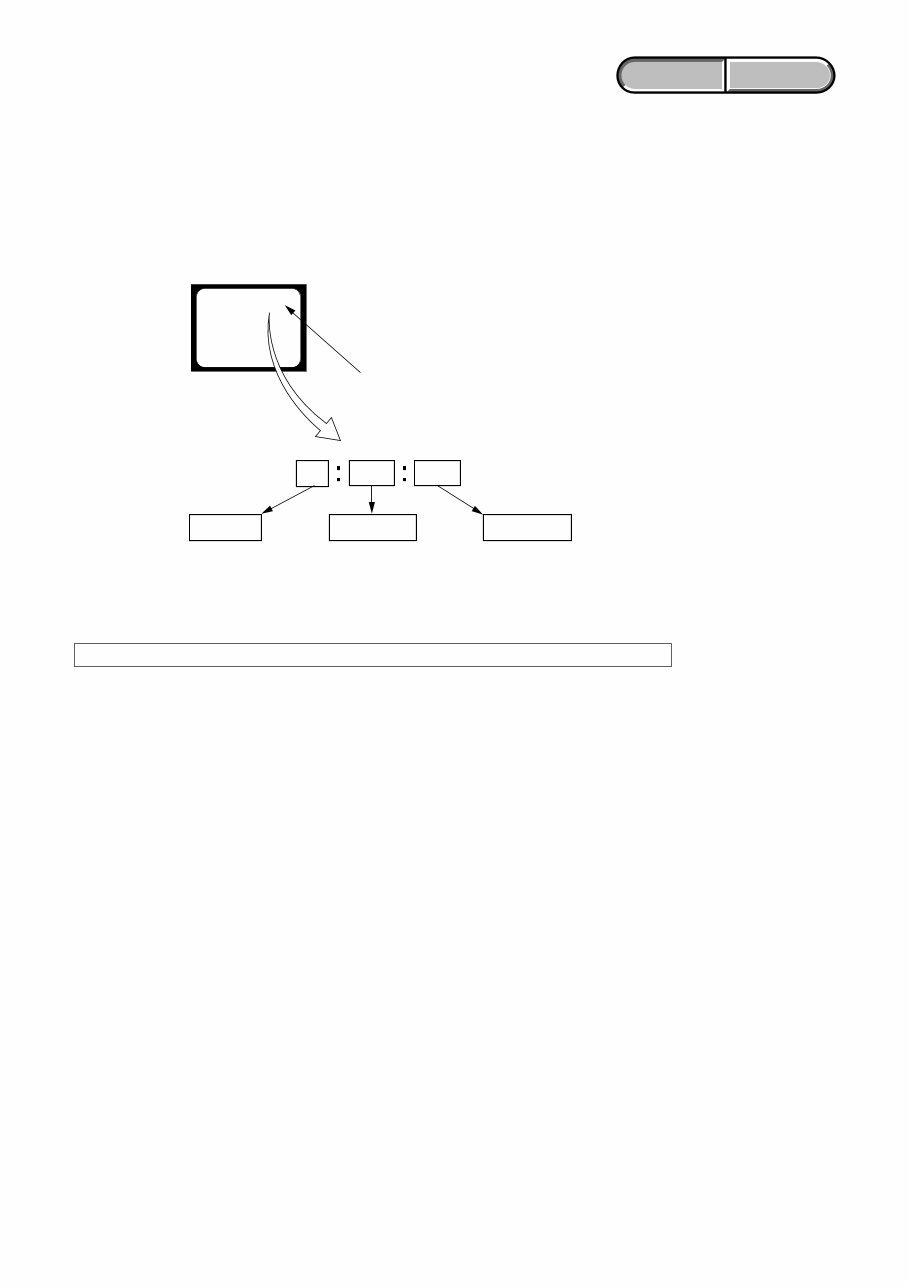
When problems occur while the unit is operating, the counter of the
viewfinder or LCD screen consists of an alphabet and 4-digit number,
which blinks at 3.2Hz. This 5-character display indicates the
“repaired by:”, “block” in which the problem occurred, and “detailed
code” of the problem.
Note: The self-diagnosis display data will be kept even if the lithium battery (BT591 of FP-959 flexible) is removed.
1 1 3 1 C
Repaired by:
Refer to page 1-4.
Self-diagnosis Code Table.
Indicates the appropriate
step to be taken.
E.g.
31 ....Reload the tape.
32 ....Turn on power again.
Block
Detailed Code
Blinks at 3.2Hz
C : Corrected by customer
H : Corrected by dealer
E : Corrected by service
engineer
Viewfinder or LCD screen
C : 3 1 : 1 1
You're Reading a Preview
What's Included?
 Lifetime Access
Fast Download Speeds
Online & Offline Access
Access PDF Contents & Bookmarks
Full Search Facility
Print one or all pages of your manual
$28.99
Sony HDR-FX1/FX1E HD VIDEO CAMERA Service Manual
Viewed 19 Times Today

What's Included?
Lifetime Access
Fast Download Speeds
Online & Offline Access
Access PDF Contents & Bookmarks
Full Search Facility
Print one or all pages of your manual
$28.99

Secure transaction
What's Included?
Lifetime Access
Fast Download Speeds
Online & Offline Access
Access PDF Contents & Bookmarks
Full Search Facility
Print one or all pages of your manual
Description
This Sony HDR-FX1/FX1E HD VIDEO CAMERA Service Manual, version 1.7, provides comprehensive technical information for professional mechanics and DIY enthusiasts. It includes service notes, disassembly instructions, block diagrams, frame schematic diagrams, schematic diagrams, printed wiring boards, repair parts list, and specifications. The manual is available in English language format.


