- 2 - ! WARNING This service information is designed for experienced repair technicians only and is not designed for use by the general public. It does not contain warnings or cautions to advise non-technical individuals of potential dangers in attempting to service a product. Products powered by electricity should be serviced or repaired only by experienced professional technicians. Any attempt to service or repair the product or products dealt with in this service information by anyone else could result in serious injury or death.
- 3 -
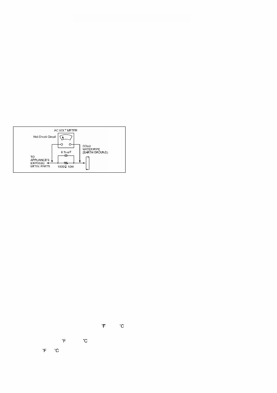
- 4 - GENERAL GUIDELINES 1. When servicing, observe the original lead dress. If a short circuit is found, replace all parts which have been over-heated or damaged by the short circuit. 2. After servicing, see to it that all the protective devices such as insulation barriers, insulation papers shields are properly installed. 3. After servicing, make the following leakage current checks to prevent the customer from being exposed to shock hazards. LEAKAGE CURRENT COLD CHECK 1. Unplug the AC cord and connect a jumper between the two prongs on the plug. 2. Measure the resistance value, with an ohm meter, between the jumpered AC plug and each exposed metallic cabinet part on the equipment such as screwheads, connectors, control shafts, etc. The resistance value must be more than 5MΩ. Figure1 LEAKAGE CURRENT HOT CHECK (See Figure 1) 1. Plug the AC cord directly into the AC outlet. Do not use an isolation transformer for this check. 2. Connect a 1.5KΩ, 10W resistor, in parallel with a 0.15µ F capacitor, between each exposed metallic part on the set an a good earth ground such as a water pipe, as shown in Figure1. 3. Use an AC voltmeter, with 1000 ohms/volt or more sensitivity, to measure the potential across the resistor. 4. Check each exposed metallic part, and measure the voltage at each point. 5. Reverse the AC plug in the AC outlet repeat each of the above measurements. 6. The potential at any point should not exceed 0.15 volts RMS. A leakage current tester (Simpson Model 229 equivalent) may be used to make the hot checks, leakage current must not exceed 0.1 milliamp. In case a measurement is outside of the limits specified, there is a possibility of a shock hazard, and the equipment should be repaired and rechecked before it is returned to the customer. ABOUT LEAD FREE SOLDER (PbF) Distinction of Pbf PCB: PCBs (manufactured) using lead free solder will have a PbF stamp on the PCB. Caution: 1. Pb free solder has a higher melting point than standard solder; Typically the melting point is 50–70 (30-40 ) higher. Please use a high temperature soldering iron. In case of the soldering iron with temperature control, please set it to 700±20 (370±10 ). 2. Pb free solder will tend to splash when heated too high (about 1100 /600 ). ELECTROSTATICALLY SENSITIVE (ES) DEVICES Some semiconductor (solid state) devices can be damaged easily by static electricity. Such components commonly are called Electrostatically sensitive (ED) Devices. Examples of typical ES devices are integrated circuits and some field-effect transistors and semiconductor “chip” components. The following techniques should be used to help reduce the incidence of component damage caused by static electricity. 1. Immediately before handling any semiconductor component or semiconductor-equipped assembly, drain off any electrostatic charge on your body by touching a known earth ground. Alternatively, obtain and wear a commercially available discharging wrist trap device, which should be removed for potential shock reasons prior to applying power to the unit under test. 2. After removing an electrical assembly equipped with ES devices, place the assembly on a conductive surface such as alminum foil, to prevent electrostatic charge buildup or exposure of the assembly. 3. Use only a grounded tip soldering iron to solder or unsolder ES devices. 4. Use only an anti-static solder removal device classified as “anti-static” can generate electrical charges sufficient to damage ES devices. 5. Do not use freon-propelled chemicals. These can generate electrical charges sufficient to damage ES devices. 6. Do not remove a replacement ES device from its protective package until immediately before you are ready to install it. (most replacement ES devices are package with leads electrically shorted together by conductive foam, alminum foil or comparable conductive material). 7. Immediately before removing the protective material from the leads of a replacement ES device, touch the protective material to the chassis or circuit assembly into which the device will be installed. CAUTION : Be sure no power is applied to the chassis or circuit, and observe all other safety precautions. 8. Minimize bodily motions when handling unpackaged replacement ES devices. (Otherwise hamless motion such as the brushing together of your clothes fabric or the lifting of your foot from a carpeted floor can generate static electricity sufficient to damage an ES device). X-RADIATION WARNING 1. The potential source of X-radiation in EVF sets is the High Voltage section and the picture tube. 2. When using a picture tube test jig for service, ensure that jig is capable of handling 10kV without causing X-Radiation. Note : It is important to use an accurate periodically calibrated high voltage meter. 3. Measure the High Voltage. The meter (electric type) reading should indicate 2.5kV,±0.15kV. If the meter indication is out of tolerance, immediate service and correction is required to prevent the possibility of premature component failure. To prevent an X-Radiation possibility, it is essential to use the specified picture tube. SAFETY PRECAUTIONS
- 5 -
FCD0212NHMK125P
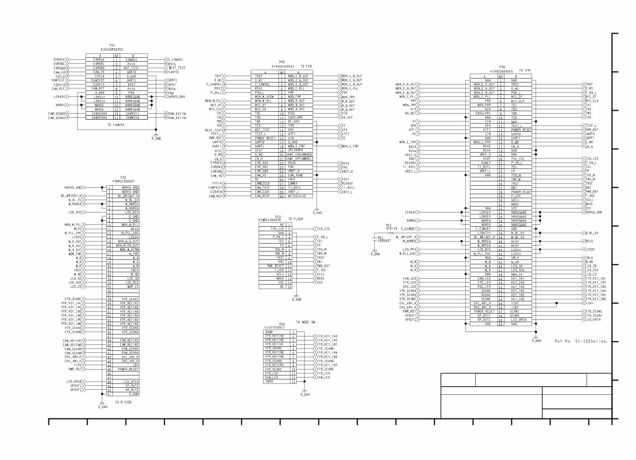
1 2 3 4 5 6 7 8 9 10 11 12 13 14 15 COMPONENT NAME EVR_CONNECT VEP000Y2A CIRCUIT BOARD NO. KR0S13 (1/1) DRAWING NO. 01/01 SCM029 A B C D E F G H I J (0)
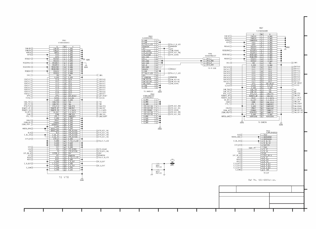
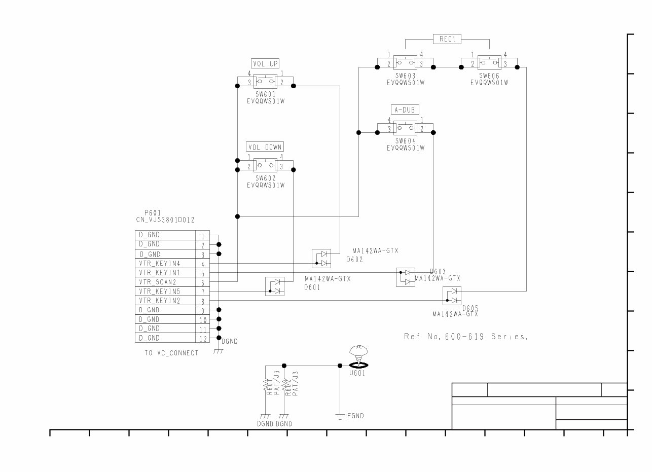
1 2 3 4 5 6 7 8 9 10 11 12 13 14 15 COMPONENT NAME VC_CONNECT VEP000Y3A CIRCUIT BOARD NO. KR0S14 (1/1) DRAWING NO. 01/01 SCM030 A B C D E F G H I J (0)
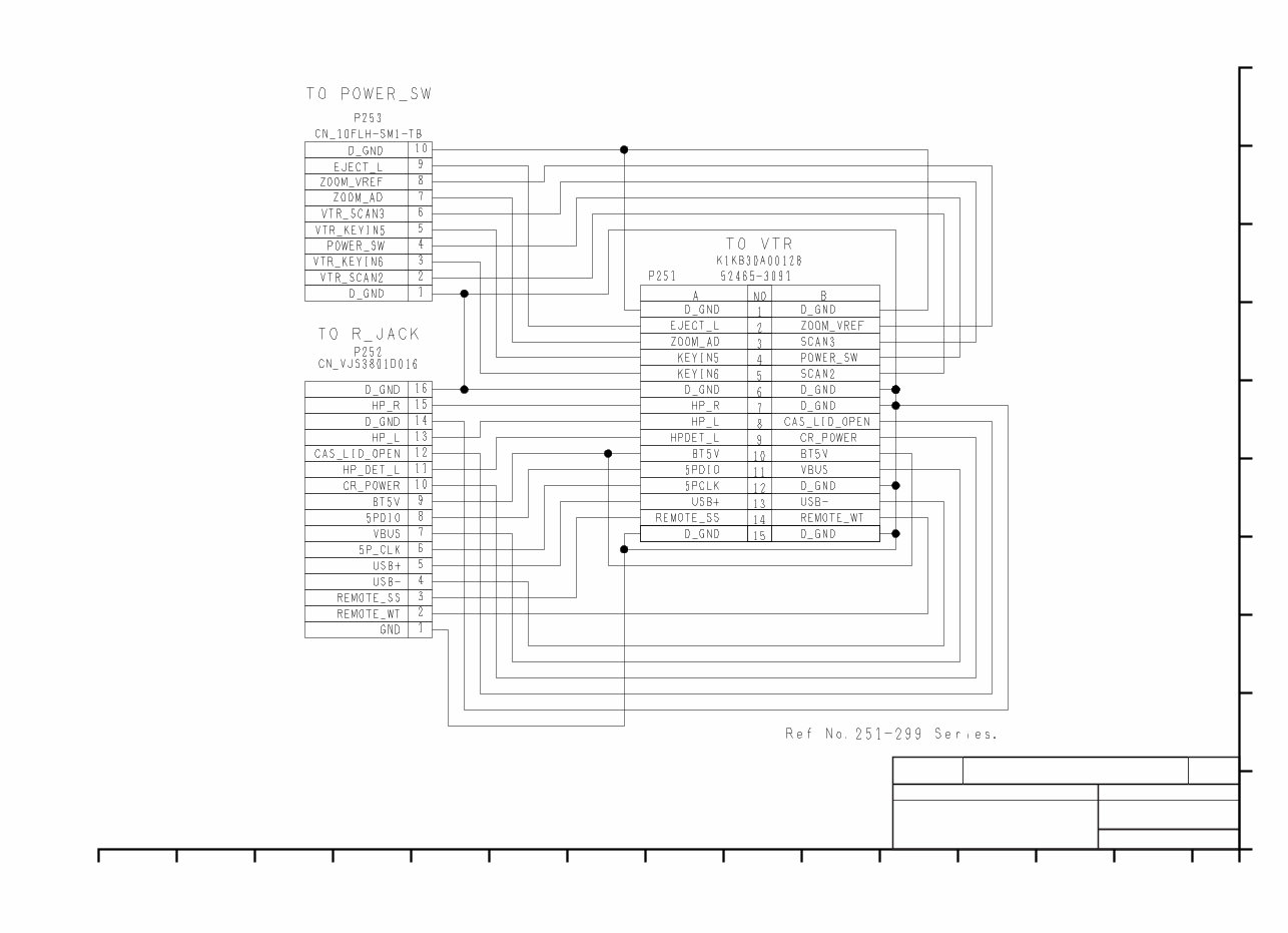
1 2 3 4 5 6 7 8 9 10 11 12 13 14 15 COMPONENT NAME REAR JACK CONNECT FLEX VEP000Y6A CIRCUIT BOARD NO. KR0S33 (1/1) DRAWING NO. 01/01 SCM031 A B C D E F G H I J (0)
1 2 3 4 5 6 7 8 9 10 11 12 13 14 15 COMPONENT NAME TOP OP VEP000Y9A CIRCUIT BOARD NO. KR6S73 (1/1) DRAWING NO. 01/01 SCM034 A B C D E F G H I J (0)
Are you experiencing issues with your Panasonic AG-DVX100P Video Camera? Instead of spending a significant amount on repairs or replacements, why not take matters into your own hands?
This comprehensive service and repair manual is the same one utilized by the Official Certified Panasonic Technicians, and it equips you with the necessary knowledge to troubleshoot and repair your Video Camera.
Within this manual, you will gain insights into:
Safety & Precautions
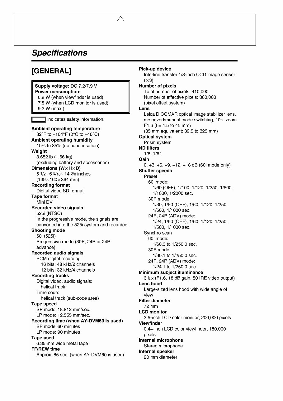
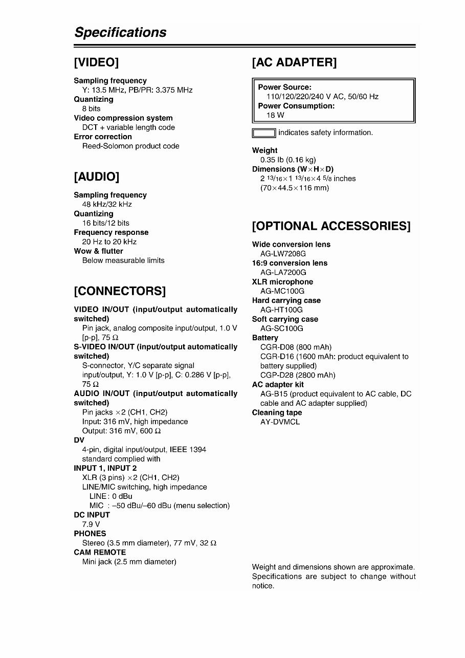
Product Specifications
Service Modes
Disassembly & Reassembly
Adjustments
Troubleshooting
Maintenance
Schematic Diagrams
Circuit Board
Exploded Views
Replacement parts list
This service manual is meticulously detailed and supplemented with images and step-by-step instructions, ensuring you can effectively service and repair your video camera.
Furthermore, you can effortlessly print this manual from any computer and printer. It's important to note that this is the OFFICIAL service and repair manual, ensuring the highest resolution and exceptional print quality.
Upon payment, you will gain instant access to this invaluable resource, eliminating shipping fees and wait times. This manual is available in English and is compatible with both Windows and MAC platforms.
If you're in search of a specific service manual, feel free to reach out to us. With one of the most extensive service manual databases, there's a high probability that we can assist you.
Take control of your repairs today with this comprehensive service and repair manual!
Recently Viewed
5,521,897Happy Clients
2,594,462eManuals
1,120,453Trusted Sellers
15Years in Business
Price:
Actual Price:
Panasonic AG-DVX100 DVX100P Service Manual & Repair Guide